

Tysso PPD Series, PPD-1700, PPD-1500 Service Manual
Service Manual
POS Peripheral Dock
PPD Series
PPD-1500 / PPD-1700
Ver.2.0
© Copyright Fametech Inc. (TYSSO) 2016

- 1 -
Table of Contents
I Part List ......................................................................................................................... 2
A. Explode................................................................................................................. 2
B. Cables & Connectors ............................................................................................ 4
II System Disassembly .................................................................................................. 8
A. Separate the Monitor from the Base ................................ ..................................... 8
B. Disassemble Panel Kit .......................................................................................... 9
C. Disassemble Base Kit ........................................................................................ 16
Table of Figures
Figure 1 Explode of the System ............................................................................................ 2
Figure 2 Cables .................................................................................................................... 4
Figure 3 I/O Board ................................................................................................................ 5
Figure 4 Resistive Type Touch Control Board ....................................................................... 5
Figure 5 A/D Board (A) ................................................................ ......................................... 6
Figure 6 A/D Board (B) ................................................................ ......................................... 6
Figure 7 OSD Board ............................................................................................................. 7
Figure 8 Invertor Board ......................................................................................................... 7
- 2 -
I Part List
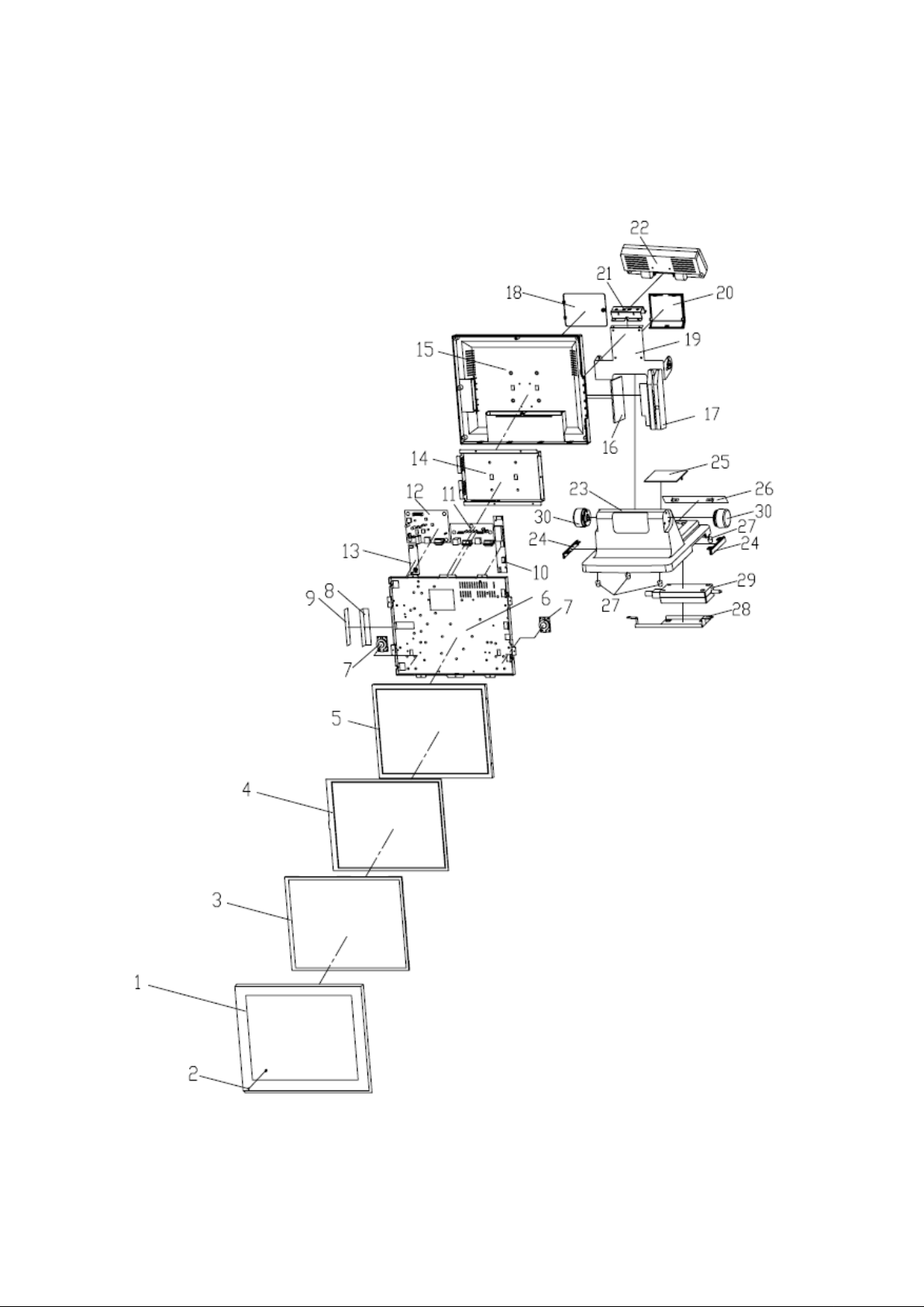
A. Explode
Figure 1 Explode of the System
- 3 -
No.
Part
Description
1
FrontBezel
Front Bezel (Black)
Front Bezel (Silver)
2
LED Indicator
Power Indicator
3
Rubber Frame
Touch Panel Rubber
4
Touch Panel
Touch Panel
5
LCD Panel *
15 inch, LED Backlight (PPD-1500)
15 inch, CCFL type (PPD-1500)
17 inch, CCFL type (PPD-1700)
6
Panel Chassis
Metal LCD Panel Chassis
7
Speaker
Speakers x 2
8
OSD Bracket Set (Plate and
Metal Bracket)
OSD Bracket x 1
OSD Plate x 1
9
OSD Control Board
OSD Board
10
Invertor *
LCD Invertor of CCFL type LCD Panel
(PPD-1700/PPD-1500)
11
I/O Board
I/O Board
12
A/D Board
A/D Board (Type A or New Type B)
13
Control Board
Touch Control Board
14
I/O Bracket
Metal I/O Bracket
15
Rear Cover
Rear Cover
16
Side Cover (Right)
Right Cover
17
MSR Kit
MSR Kit (Optional, Black or White Selectable)
18
Rear Cover
Base Rear Cover
19
Hinge Holder
Hinge Holder
20
Holder Cover
Hinge Holder Cover
21
22
Customer Display Set
(Modual and Hinge)
Rear Customer Display Set (Optional)
23
Base
Aluminum Base
24
Side Cover
Base Side Cover
25
Top Cover
Base Top Cover
26
Rear Cover
Base Rear Cover
27
Base Foot
Base Rubber Foot
28
Metal Holder
Power Adaptor Holder
29
Power Adaptor
Power Adaptor
30
Hinge Swivel
Hinge Swivel x 2
PPD-1500 / PPD-1700 SERIES Part List
* Inverter is reserved for some 15 inch/17 inch CCFL type LCD Panels only. Please consult local technical
representative for detailed information.

- 4 -
B. Cables & Connectors
Figure 2 Cables

- 5 -
No.
Description
Notes
1
Invertor Cable
The Inverter cable is ONLY for CCFL type LCD Panel.
Connect the cable to Inverter and A/D Board.
2
Power Cable
Connect the cable to A/D board and I/O Board.
3
Speakers
Connect the Speakers to the A/D Board.
4
OSD Cable
Connect the cable to A/D Board and OSD Board.
5
LVDS Cable
Connect the cable to A/D Board and LCD Panel
6
Extended LCD Backlight
Cable
This is an extended (auxularily) cable to connect the
LCD panel and connector of Inverter.
As one cable of LCD Panel is connected to the
Inverter, uset the cable to connect the other backlight
connector of Panel to Inverter.
For LED Backlight type LCD Panel:
Use the cable to connect the LCD Panel and A/D
Board.
7
Touch Cable
Connect the cable to Touch Control Board and I/O
Board
8
MSR Cable (Optional)
Connect the Optional MSR Unit to I/O Board.
9
Power Indicator
Connect the LED Indicator to OSD Board.
2
Resistive Type
Touch Panel
7
Figure 3 I/O Board
Figure 4 Resistive Type Touch Control Board
 Loading...