

Page 1

Service Manual
POS-8017F
17-inch Full Flat LCD POS Terminal
POS-8017F-D2550 / POS-8017F-i/POS-8017F-B
Version 1.0
© Copyright Fametech Inc. (TYSSO) 2015
1
Page 2

2
Page 3

Table of Contents
I Parts Description ............................................................................... 1
A Examining Your System ............................................................................. 1
Exploded View ........................................................................................................ 1
Parts Description .................................................................................................... 2
Main Board ............................................................................................................. 3
II System Disassembly ......................................................................... 9
A Before You Start .......................................................................................... 9
B Detach the Base from POS Unit ............................................................... 10
C Disassemble the POS Unit ................................ ....................................... 12
a. Remove the HDD Module .............................................................................. 12
b. Remove the Back Cover of the POS Unit ....................................................... 13
c. Remove the Metal Main Board Cover ............................................................ 14
d. Remove the Side I/O Board ........................................................................... 15
e. Remove the Side I/O Bracket with Main Power Switch .................................. 16
f. Disconnect the external Inverter (for CCFL Backlight LCD Panel only) .......... 17
g. Disconnect the external Inverter (for LED Backlight LCD Panel only) ............ 18
h. Disconnect the LVDS Cable from the Main Board .......................................... 18
i. Remove the HDD Cable ................................................................................ 19
j. Disconnect the Connectors of Speakers & Power LED Indicator .................... 19
k. Disconnect the Connector of Touch Control Panel from Main board .............. 20
l. Remove the Main Board ................................................................................ 21
m. Remove the CPU Fan & Heat Sink ................................................................ 22
n. Remove the RAM Module .............................................................................. 23
o. Remove the Speakers and LVDS Cable ......................................................... 24
p. Remove the I/O Bracket ................................................................................. 25
q. Remove the LCD Panel Set ........................................................................... 26
r. Detach the LCD Panel from Chassis .............................................................. 27
s. Remove the Power Indicator from the Front Bezel Set ................................... 28
D Disassemble the Base Kit ........................................................................ 29
a. Remove the Power Adapter and Base ........................................................... 29
b. Disassemble the Base Arm Set ...................................................................... 30
I
Page 4

Table of Figures
Figure 1 Exploded View of the System ................................................................. 1
Figure 2 Main board Layout- Front (POS-8017F-D2550) ...................................... 4
Figure 3 Main board Layout- Front (POS-8017F-i) ............................................... 5
Figure 4 Main board Layout- Back (POS-8017F-i) ................................................ 6
Figure 5 Main board Layout- Front (POS-8017F-B) .............................................. 7
Figure 6 Main board Layout- Back (POS-8017F-B) .............................................. 8
II
Page 5
I Parts Description
A Examining Your System
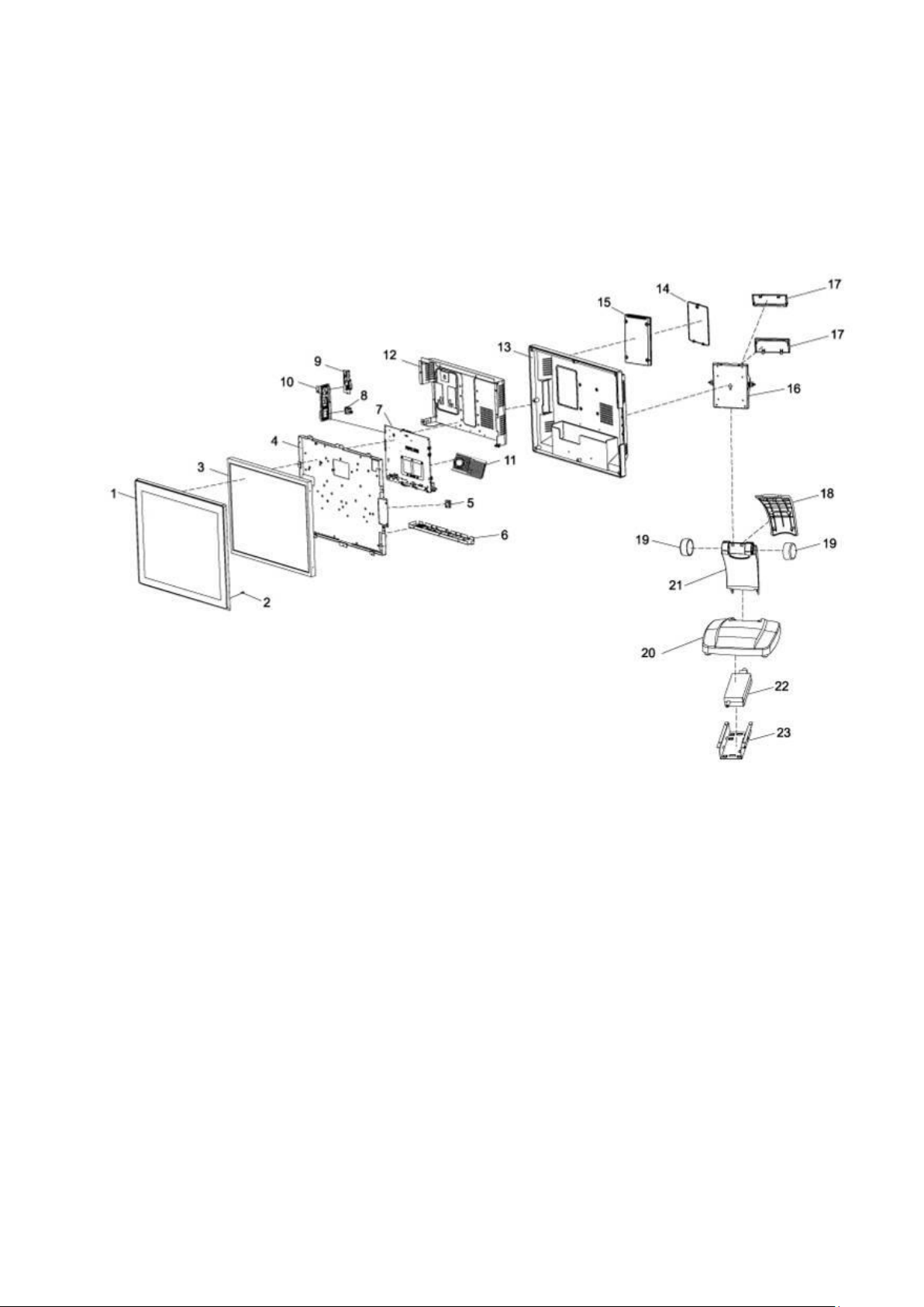
Exploded View
Figure 1 Exploded View of the System
1
Page 6
No.
Item
Description
1
Front Bezel
Capacitive Touch Front Bezel Set (Black)
Capacitive Touch Front Bezel Set (Silver)
Resistive Touch Front Bezel Set (Black)
Resistive Touch Front Bezel Set (Silver)
Front Bezel
(TYSSO Logo)
Capacitive Touch Front Bezel Set-TYSSO LOGO (Black)
Capacitive Touch Front Bezel Set-TYSSO LOGO (Silver)
Resistive Touch Front Bezel Set-TYSSO LOGO (Black)
Resistive Touch Front Bezel Set-TYSSO LOGO (Silver)
2
Power Indicator
LED Indicator
3
LCD Panel
17” LCD Panel
4
Panel Chassis
LCD Panel Chassis
5
Speaker
Speaker x 2
6
IO Bracket
IO Bracket (POS-8017F-i)
IO Bracket (POS-8017F-D2550)
IO Bracket (POS-8017F-B)
7
Main Board
Main Board (POS-8017F-i)
Main Board (POS-8017F-D2550)
Main Board (POS-8017F-B)
8
Power Switch
Main Power Switch
9
Side I/O Board
I/O Board (PS/2 Keyboard and Mouse and USB Ports)
10
Power Switch Bracket
Main Power Switch Bracket
10
Side I/O Bracket
Side I/O Bracket
11a
Cooler Kit
CPU Cooler Kit (Heat Sink and Fan)
12
Main Board Cover
Metal Main Board Cover
13
Rear Cover
Rear Cover of POS Unit
14
HDD Cover
HDD Cover
15
Hard Disk Drive
Hard Disk Drive (HDD or SSD)
16
Hinge Holder
Hinge Holder
17
Hinge Cover
Hinge Rear Cover x 2 (Up/Down)
18
Cover
Base Rear Cover
19
Swivel Set
Hinge Swivel x 2
20
Base
Metal Base
21
Holder
Base Holder
22
Power Adapter
Power Adapter
23
Metal Holder
Power Adapter Holder
Parts Description
** The optional peripherals and parts may not include in the system. Please contact the local
representatives or technical support personnel of the providers for ordering information.
2
Page 7
No.
Connector/Slot
Connection/Installation Notes
1
HDD Connectors
Please use the HDD cable and connect to the Hard
drive. (Black: Data; White: HDD power)
2
Connector of Capacitive Touch
Control Unit.
ONLY when connect to the Capacitive Touch Panel
3
Connector of Side I/O Board
Connect to the Side I/O Board (PS/2 and USB)
4
Connector of Resistive Touch
Control Unit.
ONLY when connect to the Resistive Touch Panel
5
Connector of PWR Indicator
Connect the Power Indicator to the main board.
6
Connector of Power Switch
Connect the Power Switch to the main board.
7
LVDS Connector
Use the LVDS Cable and connect to the LCD Panel.
8
Audio Connector (Speaker)
Connect the Speaker to the main board.
9-1
Connector of Side I/O (MSR)
Connect the Side I/O Connector (MSR) to the main
board.
*Reserved for MSR/i-Button Module
9-2
Connector of Side I/O (USB)
Connect the Side I/O Connector (USB) to the main
board.
*Reserved for MSR/i-Button Module
10
Inverter Connector
Please use Inverter Cable and connect to the Inverter.
11
RAM Module Slot
Install the RAM module to the main board.
12
CPU FAN Connector
Install the CPU Cooler kit(CPU Fan & Heat Sink)
*For POS-8017F-I only
Main Board
● Main Board Connection / Installation Notes
The table below is the descriptions of the connectors of the main board.
Each connector/slot is used for the specified part or optional peripheral.
Please refer to the notes as below and examine the layouts of the main boards to locate
the correct connectors so as to complete the installation.
i.e.:
To connect the HDD to the main board, please use the HDD cable and locate the
matched connector on the main board; then connect the HDD cable to the Hard Drive.
3
Page 8

1
2 6 3 5 7
9-1
9-2
11 4 8
12
CPU
Fan
Connector
(Reserved)
10
Modular Customer Display
Connector
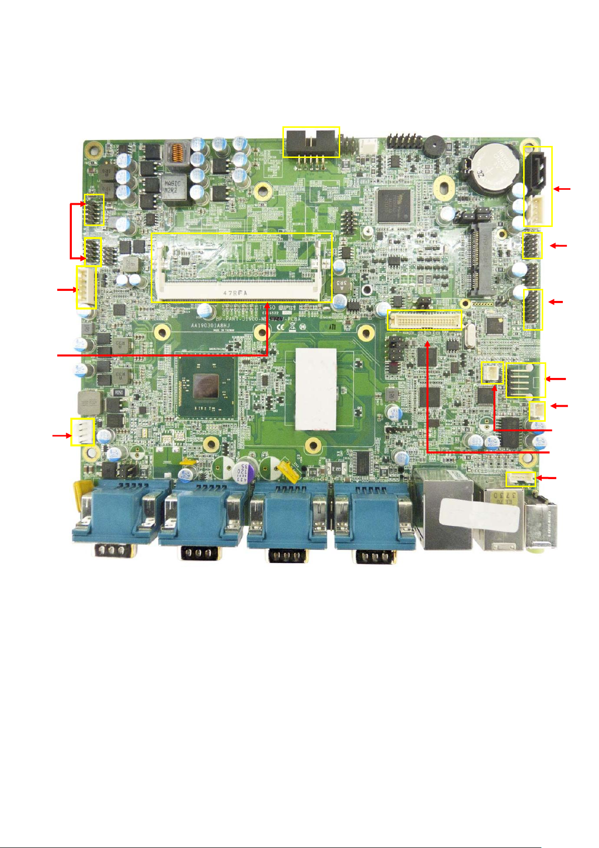
● POS-8017F-D2550
Front View
Figure 2 Main board Layout- Front (POS-8017F-D2550)
4
Page 9

1 2 6
3 5 7
9-1
9-2
11 4 8
12
CPU
Fan
Connector
10
Modular Customer Display
Connector
● POS-8017F-i
Front View
Figure 3 Main board Layout- Front (POS-8017F-i)
5
Page 10
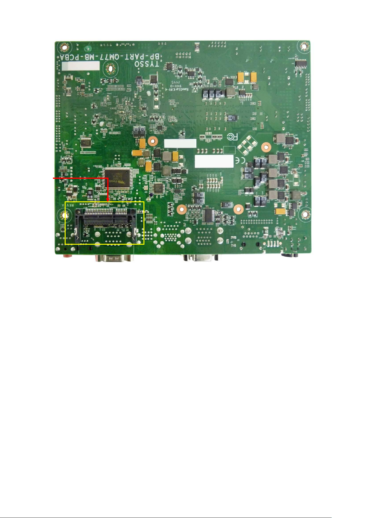
CFAST
Slot
Figure 4 Main board Layout- Back (POS-8017F-i)
6
Page 11
1
2 6 3
5
7
9-1
9-2
11
4
8
12
CPU
Fan
Connector
10
Modular Customer Display
Connector
● POS-8017F-B
Front View
Figure 5 Main board Layout- Front (POS-8017F-B)
7
Page 12

CFAST
Slot
Figure 6 Main board Layout- Back (POS-8017F-B)
8
Page 13

II System Disassembly
A Before You Start
To prevent injuries to the LCD Panel, Carefully Place the POS on a flat, clean and
stable surface (for example: a stable long table)
Prepare additional cushioned material (for example: a soft, clean blanket).
Terminate the application running in the POS system, and shut down the operation
system.
Turn-off the POS system, Embedded Thermal Receipt Printer and unplug the power
cable from the electrical outlet.
Note:
There are no serviceable parts or components in the POS system or peripherals.
DO NOT Modify any parts of POS systems or use non-qualified parts or peripherals.
For maintenance or replacement, please consult the technical personnel and contact
the local representative for purchasing the new peripherals and parts
9
Page 14

Tilt the POS unit horizontally
Remove the Hinge Holder Covers
1. Tilt the POS unit horizontally.
2. Unplug the cables and connectors
from the POS unit.
Unplug the cables
from the bottom I/O ports
3. Use a soft and cushioned material
and place it on the table.
4. Carefully place the POS Terminal
side down on the soft and
cushioned surface.
This can protect the LCD Screen
from damage.
5. Use a screw driver to lift up and
remove the 2 hinge holder covers.
Remove the Hinge Holder Cover
Hinge Holder Cover
Hinge Holder Cover
B Detach the Base from POS Unit
10
Page 15

Detached Base (Left) and POS Unit (Right)
6. Loosen the 4 screws and detach
the base holder from the POS unit.
(as yellow marks indicated)
Remove the Securing Screws on the
POS unit
11
Page 16

The Securing Screw of HDD Cover
HDD Module with HEX Spacer
Hard disk with bracket
The detached bracket and HDD Mylar (left)
and Hard Disk Drive (right)
1. Place the POS unit on a flat,
clean and stable location
with soft cushioned material.
2. Loosen the securing screw of
HDD Cover.
3. Use a HEX Nut Key screw driver
to remove the Spacer.
4. Carefully pull the HDD module
upward and disconnect the
HDD cables from the HDD
module.
5. Detach the HDD bracket from
the hard disk.
Store them at a secured place.
Detach the HDD bracket from HDD Drive
HEX Spacer
C Disassemble the POS Unit
a. Remove the HDD Module
12
Page 17

Securing Screws of Back Cover
(as yellow marks illustrated)
POS unit with back cover removed
1. Loosen and remove the securing
screws of the Back Cover.
Remove the securing screws of the
Back cover
2. Remove the Back Cover from the
POS unit.
b. Remove the Back Cover of the POS Unit
13
Page 18

Metal Main Board Cover
(as red mark illustrated)
1. Loosen and remove the securing
screws of the
Metal Main Board Cover..
Remove the securing screws of the
Metal Main Board Cover
c. Remove the Metal Main Board Cover
The yellow marks indicate the Securing Screws of Metal Main Board Cover
( Image TOP, Left and Bottom/Right):
14
Page 19

Side I/O Board connecting to the Main Board
Side I/O Board
1. Unplug the I/O connector from
the Main Board
2. Loosen the securing screws to
remove the Side I/O board.
Loosening the Securing Screws of the
Side I/O Board
d. Remove the Side I/O Board
15
Page 20

Side I/O Bracket and Main Power Switch
connecting to the Main Board
Side I/O Bracket and Main Power Switch
Tips: Replace the Main Power Switch
To replace the Main Power Switch, press the
two latches on the two sides of Power Switch
(Yellow Arrows) and push out the switch
(Red Arrow indicated).
3. Disconnect the connector of
Main Power Switch
(Black/White twisted-pair cables)
from the Main Board.
4. Loosen the securing screws to
remove the Side I/O board.
Loosening the Securing Screws of the
Side I/O Bracket.
e. Remove the Side I/O Bracket with Main Power Switch
16
Page 21

Inverter and cable to the Main Board
1. Disconnect the cable connector
of Inverter from the Main Board.
Disconnect the Inverter from Main Board
2. Disconnect the 4 connectors of
Inverter
3. Remove the Inverter from POS
Unit.
f. Disconnect the external Inverter (for CCFL Backlight LCD Panel only)
The POS-8017F series POS terminal provides two types of LCD panel (LED Backlight or
CCFL Backlight).
For CCFL type LCD panel, there is an external Inverter installed in the POS terminal.
Please follow the instructions as below to disconnect and remove the external Inverter.
17
Page 22

Inverter cable connected on the Main Board
Disconnect the cable of LCD Panel to
remove the inverter
(as yellow mark indicated).
Disconnect the Inverter onboard
LVDS Cable connected on the Main Board
Disconnect the LVDS cable from the
Main Board
The LVDS Cable is disconnected
from the Main Board
g. Disconnect the external Inverter (for LED Backlight LCD Panel only)
h. Disconnect the LVDS Cable from the Main Board
18
Page 23

HDD Cables (Data cable and Power cable)
Disconnect the HDD cables from the
Main Board.
Remove the HDD Cables from the Main Board
The connectors of
Power LED Indicator
(Blue/White twisted pair cable)
and
Speakers
(Red/Back twisted pair cable)
1. Disconnect the Power LED Indicator
(blue-white twisted pair cable)
from the Main Board.
2. Disconnect the Speaker
(RED/Black twisted pair cable) from
the Main Board.
Power LED Indicator
Speakers
i. Remove the HDD Cable
j. Disconnect the Connectors of Speakers & Power LED Indicator
19
Page 24

Disconnect the connector of Touch Control Panel
from Main Board
Front Bezel with Touch Control Panel
The Touch Control Unit is embedded
in the Main Board.
To disconnect the Touch Control
Panel from the Main Board:
Disconnect the connector of Touch
Control Panel from the Main Board
k. Disconnect the Connector of Touch Control Panel from Main board
20
Page 25

Main Board of the POS Unit
HEX Screws on the I/O Bracket
Securing Screws of the Main Board
1. Use a HEX Nut Key screwdriver to
remove the hex mounting screws on
the I/O bracket
2. Remove all of the securing screws
of the Main Board
3. Slightly move the Main Board
forward and take the Main Board out
of the POS Unit
l. Remove the Main Board
21
Page 26

CPU Fan & Heat Sink (left) and Main Board (Right)
1. Disconnect the CPU Fan
connector.
2. Turn over the Main Board and
remove the securing screws
(or latches) to release the
CPU Fan & Heat Sink
m. Remove the CPU Fan & Heat Sink
Note:
The CPU Fan & Heat Sink set is different depending on the types of Main Boards.
Please consult the technical service before maintenance and replacement.
22
Page 27

Main Board
1. Release the latches on the two sides
of the RAM module slot.
2. The RAM Module would lift up to a
degree (approximately 30° ).
Gently slide the module out of the slot
3. Repeat the step 1~2 to remove the
other RAM Module
n. Remove the RAM Module
23
Page 28

Speakers, LVDS Cable of POS Unit
LVDS Cable of the LCD Panel
Detached Speakers
1. Loosen the securing screws of the
speaker.
2. Remove the black tapes of
LVDS Cable, Speakers, and LED
Indicator.
3. Arrange the LED cable and store
all the detached cables and parts
in a secure location.
The tapes on the POS Unit are removed.
LVDS Cable
o. Remove the Speakers and LVDS Cable
24
Page 29

Securing Screws of the I/O Bracket
LCD Panel Set of POS Unit
(I/O Bracket is removed)
Loosen the 3 securing screws and
then pull downward to remove the
I/O Bracket
Loosen the Securing Screws
p. Remove the I/O Bracket
25
Page 30

Securing Screws of LCD Panel
Front Bezel with Touch Panel
1. Loosen the securing screws of the
LCD Panel Chassis to remove the LCD
Panel.
Loosen the securing screw of Chassis
2. Lift up the LCD Panel with Chassis from
the Front Bezel (with Touch Panel)
The LCD panel with chassis
q. Remove the LCD Panel Set
26
Page 31

LCD Panel with Panel Chassis
Detached LCD Chassis (Left) and LCD Panel(Right)
There are two screws on both sides of
the LCD Panel Set.
Loosen the screws and then remove
the chassis from the panel
Securing Screws of the Chassis
(Left and Right)
r. Detach the LCD Panel from Chassis
Note:
Store the removed LCD Panel on a secure location with proper protection.
27
Page 32

Front Bezel Set with Touch Panel
1. Use a small tool to loosen the snap-in
clip with care.
2. Remove the Main Power LED
Indicator from Front Bezel set.
3. Use a new LED Indicator and push
into the snap-in slot of the
Front Bezel Set.
4.
Power LED Indicator
s. Remove the Power Indicator from the Front Bezel Set
Warning:
DO NOT DETACH the Front Bezel Set (with Touch Panel)
Please purchase the whole Set for replacement.
28
Page 33

The Base with Adaptor Module
Adaptor Module (Adaptor and holder)
The securing screws on the Base
1. Turn over the base and loosen the
securing screws to remove the
power adaptor.
Remove the screws from the Base.
2. Disassemble the Base Arm from the
Base
Loosen the securing screws to remove
the Base Arm
Base Arm (left) and Base (right)
D Disassemble the Base Kit
a. Remove the Power Adapter and Base
29
Page 34

Turn and remove the swivels from Base Arm Set
Base Bracket (left) and Base Arm (right)
1. Turn and remove the two swivels
and then detach the Base Bracket
from the Base Arm Set.
2. Loosen the four securing screws of
hinge to remove the base bracket
from Base Arm Set
Hinge Swivel
Hinge
Base Bracket
b. Disassemble the Base Arm Set
30
Page 35

Date
Version
Note
Description
Dec. 12, 2015
Ver. 1.0
Preliminary version
1st released
Revision History
31
 Loading...