

Page 1
i
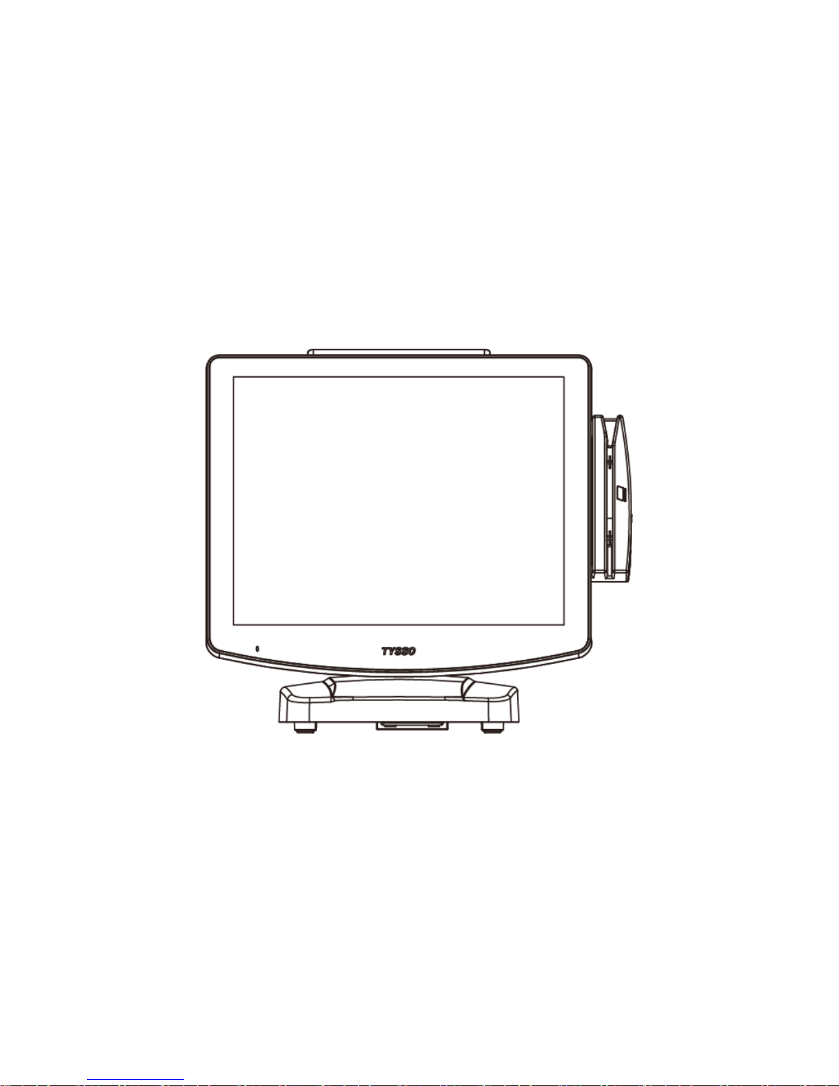
POS-6000 Series
User Manual
POS-6000-i
Ver. 1.0
© Copyright Fametech Inc. (TYSSO), 2014
Page 2

i
General Information
ABOUT THIS MANUAL
The purpose of this user’s manual is to provide general information on TYSSO’s
POS-6000 series POS Terminal and to show the users how to configure the hardware-related
configurations.
The information in this manual is subject to change without notice due to rapid improvement on
IT technology. Users can get the most up to date information from our web sites:
Uhttp://www.fametech.com.twU
DISCLAIMER
This manual has been examined for accuracy. While precaution has been taken in the
preparation of this manual, neither the manufacturer takes no liability for errors or omissions nor
assume any responsibility for damage(s) incurred directly or indirectly from errors, omissions, or
discrepancies of this manual.
IN NO EVENT WILL THE VENDOR BE LIABLE FOR DIRECT, INDIRECT, SPECIAL,
INCIDENTAL, OR CONSEQUENTIAL DAMAGES ARISING OUT OF THE USE OR INABILITY
TO USE THIS PRODUCT OR DOCUMENTATION, EVEN IF THE POSSIBILITY OF SUCH
DAMAGES HAS BEEN ADVISED. IN PARTICULAR, THE VENDOR SHALL NOT HAVE
LIABILITY FOR ANY HARDWARE, SOFTWARE, OR DATA STORED OR USED WITH THE
PRODUCT, INCLUDING THE COSTS OF REPAIRING, REPLACING, OR RECOVERING SUCH
HARDWARE, SOFTWARE OR DATA.
WARNING
The terminal has been tested and found to comply with the limits for a Class a digital device,
pursuant to Part 15 of the FCC rules. These limits are designed to provide reasonable protection
against harmful interface in a residential installation. This equipment can generate and radiate
radio frequency energy and, if not installed and used according to the instructions, may cause
harmful interference to radio communications. However, there is no guarantee that interface will
not occur under particular installation. If this equipment does cause harmful interference to radio
or television reception, which is found by turning the equipment off and on, the user is
encouraged to try to correct the interface by one or more of the following measures:
Reorient or relocate the receiving antenna
Increase the distance between the equipment or device
Connect the equipment to an outlet other than the receiver’s
Consult a dealer or an experienced radio/TV technician for assistance
Page 3

ii
CAUTION
The system is provided with a battery-powered Real-Time Clock circuit. There is a danger of
exposing and personal injury if the battery is incorrectly replaced or mistreated. Do not attempt to
disassemble the battery, immerse it in the water or expose it to fire.
WARRANTY LIMITS
If the product and the parts are disassembled by any person other than the authorized
technicians, the warranty will be terminated. The users should consult his/her dealer for any
technical problems. Warranty does not cover any damage caused by improper use.
TRADE MARKS AND SERVICE MARKS
TYSSO is a registered trademark of FAMETECH INC.
Other brand and product names are trademarks and registered trademarks and service marks of
their respective owners.
Page 4

iii
IMPORTANT SAFETY INFORMATION
Read following instructions carefully.
Use only parts, especially power adapter, recommended by the manufacturer; unapproved
parts may be hazardous.
Before plugging the power cord into the AC inlet of the power supply unit, make sure that
the voltage applied to the power outlet is within the specified range (100V ~240V).
Improper power source voltage range will cause damage to the power supply unit.
Power off the system and remove the power adapter while cleaning the system.
Before powering on the system, make sure all the peripherals are firmly installed.
Do not use the system near water, such as a bathtub, a washbowl, a kitchen sink, a laundry
tub, and a swimming pool. Do not expose the machine under direct sunlight, and keep it
away from any heat source.
Do not place the system on an unstable cart, stand or table. If the machine falls, it may injure
a person or cause serious damage to the appliance.
The system is equipped with a three-wire grounded plug with a third (grounding) pin. This is a
safety feature. If your outlet does not accommodate the three-wire plug, have an electrician
install a correct outlet, or use an adapter to ground the appliance safely. Do not leave out the
safety purpose of the grounded plug.
Do not allow anything to rest on the power cord. Do not locate the system where people may
walk on the cord.
Do not make the power outlet and extension cords overload. Overload can result in fire or
electric shock.
Do not push any object into the computer cabinet. Dangerous voltage points may be touched
and the parts may be shorted out resulting in fire or electric shock.
Do not attempt to service the system on your own. Opening or removing cover can expose
you to dangerous voltage or other hazards.
Power off the system before installing or removing non-PNP (plug and play) devices.
If any of the following situations occurs, unplug the systems from the power outlet
immediately and consult with a qualified service person:
1. The power cord or plug is damaged or frayed.
2. Liquid is spilled into the system.
3. The system is dropped or the cabinet is damaged.
When the system is not in use, cover the system and store it with care.
Page 5

iv
Contents
General Information ............................................................................................................. i
ABOUT THIS MANUAL ...................................................................................................... i
DISCLAIMER ..................................................................................................................... i
WARNING ......................................................................................................................... i
CAUTION ......................................................................................................................... ii
WARRANTY LIMITS ......................................................................................................... ii
TRADE MARKS AND SERVICE MARKS .......................................................................... ii
IMPORTANT SAFETY INFORMATION ............................................................................. iii
1. Product Overview ......................................................................................................... 1
1.1. Packing .................................................................................................................... 1
1.2. Specifications ........................................................................................................... 2
1.3. Parts Descriptions .................................................................................................... 5
1.4. I/O Ports .................................................................................................................. 7
2. POS Installation ............................................................................................................ 9
2.1. Unpack Your POS .................................................................................................... 9
2.2. Install Your POS System ........................................................................................ 10
2.3. Plug AC Power Cord to the POS............................................................................. 11
2.4. Replace Hard Disk ................................................................................................. 12
2.5. Install the Modular Customer Display (Optional) ...................................................... 13
2.6. Configuration of Modular Customer Display ............................................................ 14
3. BIOS Setup ..................................................................................................................15
Overview......................................................................................................................... 16
Default Configuration....................................................................................................... 17
Entering the BIOS Setup Utility ........................................................................................ 17
3.1. Main....................................................................................................................... 19
3.2. Advanced ............................................................................................................... 20
3.2.1. ACPI Power Management Configuration ................................................................... 21
3.2.2. PC Health Status ....................................................................................................... 22
3.2.3. CPU Configuration..................................................................................................... 28
3.2.4. SATA Configuration ................................................................................................... 29
3.2.5. Intel Anti-Theft Technology Configuration................................................................... 31
3.2.6. USB Configuration ..................................................................................................... 32
3.2.7. F71889 Super IO Configuration ................................................................................. 33
3.2.8. Second Super IO Configuration ................................................................................. 36
3.2.9. Network Stack ........................................................................................................... 39
3.2.10. CPU PPM Configuration ............................................................................................ 41
3.2.11. Serial Port Control ..................................................................................................... 42
3.2.12. Backlight Control ....................................................................................................... 43
Page 6

v
3.3. Chipset .................................................................................................................. 44
3.3.1. PCH-IO Configuration ................................................................................................ 45
3.3.2. System Agent (SA) Configuration .............................................................................. 49
3.4. Boot ....................................................................................................................... 53
Tips: How to set the Boot Option............................................................................................. 55
3.5. Security.................................................................................................................. 57
3.6. Save & Exit ............................................................................................................ 58
3.7. Updating the BIOS ................................................................................................. 59
4. Install the Support Softwares of POS Terminal .....................................................61
4.1. Microsoft .NET Framework 3.5 (for Windows XP only) ............................................ 64
4.2. Intel Chipset Software Installation Utility.................................................................. 66
4.3. Intel HD Graphics Driver ......................................................................................... 68
4.4. LAN Driver ............................................................................................................. 71
4.5. Audio Driver ........................................................................................................... 73
5. Install the Touch Screen Driver ................................................................................74
5.1. Install the Driver of Resistive Type Touch Panel ...................................................... 75
5.2. Touch Screen Calibration (Resistive Type) .............................................................. 83
6. Peripherals Test ..........................................................................................................87
6.1. Install the Wi-Fi Driver (Optional) ............................................................................ 88
6.2. Test Your Magnetic Stripe Card Reader(MSR) and i-Button Module ......................... 91
6.3. Test Your Customer Display .................................................................................... 93
6.4. Test Your Cash Drawer ........................................................................................... 95
7. Appendix ......................................................................................................................97
Mainboard Technical Document .............................................................................. 97
COM Ports Pin Assignment .................................................................................... 98
COM 5 Jumper Setting (JP19) ................................................................................ 99
Cash Drawer Power Select (J3) ............................................................................ 100
Jumper Location and Settings .............................................................................. 101
Jumper Settings ................................................................................................... 102
Page 7

vi
Page 8

- 1 -
1. Product Overview
1.1. Packing
POS Unit
Contents
POS Unit x 1
Power Adapter (External, hitten under base) x 1
AC Power Cord x 1
Driver/Utility DVD x 1
Optional Accessories
Magnetic Stripe Card Reader (MSR)/i-Button Module
Rear Customer Display
Wi-Fi module
Secondary Display
High Power Adaptor of extra +24VDC output
(+12VDC/180W,4-pin Connector with Lock ,Power Input: 100~240 VAC, 50/60HZ)
* For more information relating to the other optional peripherals, please contact the local representatives or
technical support personnel of the providers.
AC Power Cord
Driver/Utility DVD
Page 9

- 2 -
1.2. Specifications
Model
POS-6000-i
Main Board
CPU
3rd Generation Intel® Core
TM
processors (22nm process technology)
Intel® Core™ i7-3610QE (6M Cache, up to 3.3 GHz); 45W
Intel® Core™ i5-3610ME (3M Cache, up to 3.3 GHz); 35W
Intel® Core™ i3-3120ME (3M Cache, 2.4 GHz); 35W
2nd Generation Intel® CoreTM processors (32nm process technology)
Intel® Core™ i7-2710QE (6M Cache, up to 3.0 GHz); 45W
Intel® Core™ i5-2510E (3M Cache, up to 3.1 GHz); 35W
Intel® Core™ i3-2330E (3M Cache, 2.2 GHz); 35W
Intel® Celeron® B810 (2M Cache, 1.6 GHz); 35W
Chipset
Intel® QM77 Express chipset
System Memory
2 x 204 pin DDR3 SO-DIMM Socket 1333MHz, up to 16GB
Graphics
Intel® HD Graphics 4000
OS Support
Linux, POS Ready 2009, POS Ready 7,
Windows XP Pro, Vista, Windows 7
Display
Display Type
15” Full Flat LCD Monitor
Brightness
250 nits
Resolution
1024 x 768 Pixel
Touch Screen
5 Wire Resistive Type or Projective Capacitive
Tilting Angle
Fixed 50 Degree
Storage
HDD
1x 2.5” SATA
Compact Flash
1 x Cfast Slot for SATAI / SATA II
Interface
Serial
4 x RS-232 DB9 with Power Selected 5/12V
1 x RJ-45 with Power Selected 5/12V
USB
2 x USB3.0 (External),
4 x USB2.0 (External),
3 x USB 2.0
(Internal, reserved for touch screen, Wi-Fi, and MSR)
SATA
1 x SATA 3.0
SATA Power Connector
1 x 4-pin Power connector
PS/2
1 x mini-DIN-6 port for PS/2 Keyboard/Mouse
LAN
1 x RJ-45, Giga LAN Support
VGA
1 x DB-15, Female
DC Out
1 x 12VDC Jack)
Cash Drawer
1 x RJ-11, +12/+24 VDC selectable
Audio
1 x Line Out, 1 x MIC In,
1 x Internal Speaker
Page 10

- 3 -
Others
Power Input
+12VDC 90W,4-pin Connector with Lock
(External Adaptor: 100~240 VAC, 50/60HZ)
Color
White, Black, Orange
Compliance
FCC / CE / WEEE / RoHS
Weight
6.7 Kg
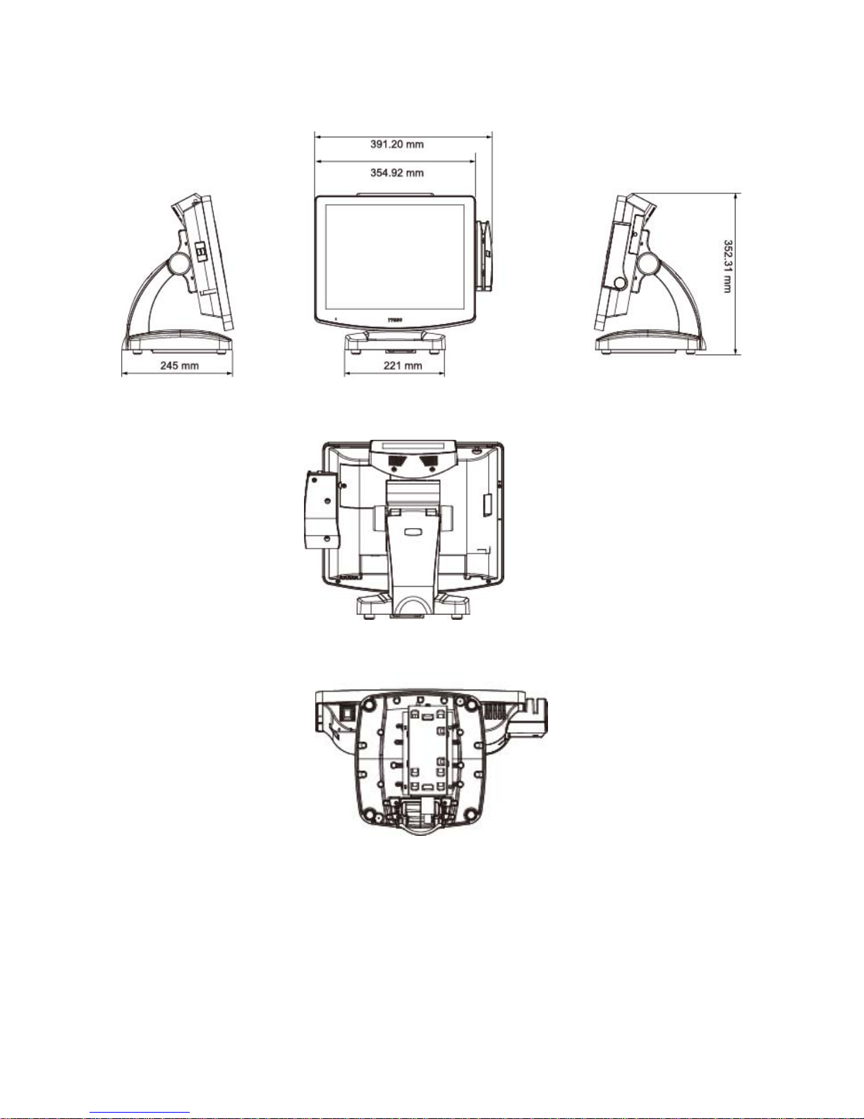
Dimension (mm)
391.2(W) x 352.3(H) x 245.0(D)
Operating Temperature
0°C~40°C
Operating Humidity
20% ~ 80% RH non-condensing
Storage Temperature
-20°C~ 60°C
Storage Humidity
20% ~ 85% RH non-condensing
Modular Customer Display (Optional)
General
Display Type
Vacuum Fluorescent Display
Brightness
700 cd/m2
Number of Columns
20 x 2
Character Size (mm)
6.4 x 9.2 (W x H), 5x7 dot matrix
Command Set
ESC/POS
Font Character Support
96 Alphanumeric & 13 international
Interface
RS-232.
Others
Power Input
+9VDC~+12VDC(RS-232) or +5VDC (USB)
Power Consumption
4.5 W (RS-232), 1.5 W (USB)
Material
ABS
Compliance
CE, FCC
Display Unit
218 x 87 x 45 mm
Operating Temperature
0°C~40°C
Storage Temperature
-10°C~ 50°C
Relative Humidity
0% - 90% RH, non-condensing
Optional Peripherals
MSR/i-Button Module
3 Track, PS/2 or USB or COM
Dallas Key RS232 I/F
2nd Display
10.4” LCD Display, with or without Touch
Wi-Fi
USB interface Module with Antenna
High Power Adaptor **
For +24VDC output of external Thermal receipt printer
(+12VDC/180W,4-pin Connector with Lock ,Power Input:
100~240 VAC, 50/60HZ)
* For more information relating to the other optional peripherals, please contact the local
representatives or technical support personnel of the providers.
** The High Power Adaptor are reserved for customized request.
Please consult the professional technical support personnel befor purchasing.
Page 11
- 4 -
Dimensions
Left View Front View Right View
Rear View
Bottom View
Page 12
- 5 -
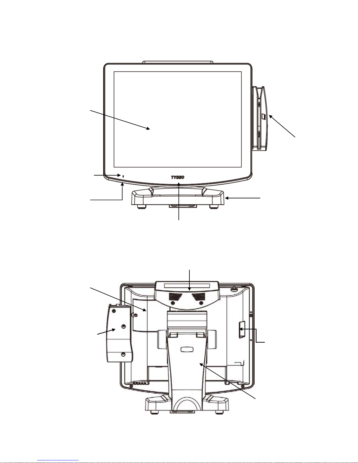
1.3. Parts Descriptions
Front View
Rear View
LCD
Touch Screen
Power Indicator
MSR/i-Button Module
(Optional)
MSR/i-Button
Module
(Optional)
Base
Modular Customer Display
(Optional)
Base Rear Cover
Side I/O Ports
HDD Cover
LED Indicator
(Lit when power-on)
Power Switch
Page 13

- 6 -
Side View
Bottom View (POS Unit)
Bottom View (Base)
Button I/O Ports
Power Adaptor
Left View
Right View
MSR/i-Button
Module
(Optional)
Side I/O Ports
Power Switch
Page 14
- 7 -
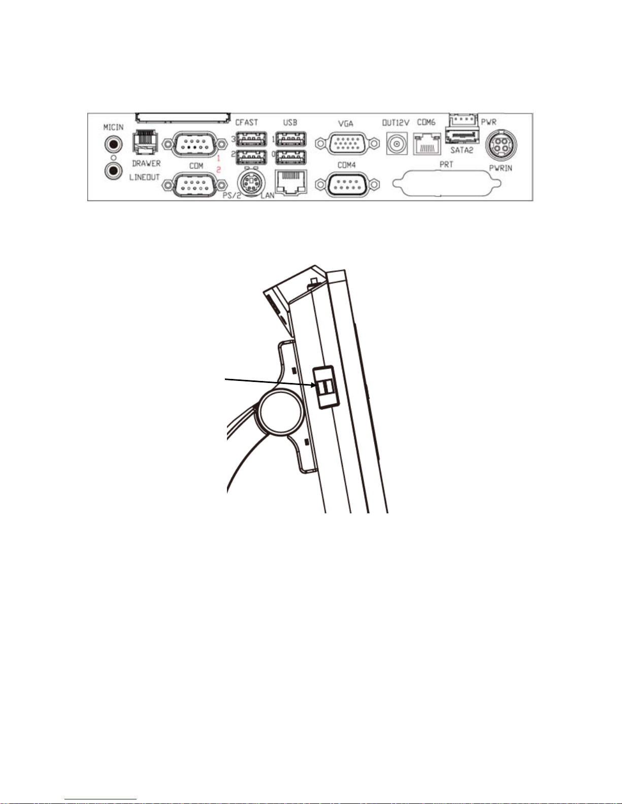
1.4. I/O Ports
Bottom I/O Ports
Side I/O Ports
Side I/O ports
(USB)
Page 15

- 8 -
I/O Ports Descriptions:
I/O Port
Description
USB
Connect devices with USB connectors. There are 6 external USB ports
available, (4 locate on the bottom and 2 left side ports).
2 x USB 3.0 (located on the bottom).
4 x USB 2.0 (2 located on the bottom and 2 on the left side).
PS/2
1 x mixed PS/2 connector
PWR IN
1 x 4-pin rounded-power-jack for connecting an AC to DC +12V power adapter.
Serial (COM)
External
3 x RS-232 DB9 (COM 1/COM 2 / COM 4), support power RI/+5VDC/+12VDC
1 x RJ-45 (COM 6), support power RI/5/12V,
* Please refer to BIOS Setup Utility (3.2.11 Serial Port Control) for power
configurations
Internal
COM 3: reserved for mix PS/2
COM 5: +5VDC/+12VDC Power Selectable on pin-9 by jumper (JP19)
*Please refer to Appendix: (COM 5 Jumper Setting) for power configurations
SATA
1 x SATA 3.0
1 x 4-pin SATA power connector
AUDIO
OUT
Earphone or speaker connector with 2 internal speakers.
MIC IN
Microphone connector
DC OUT
1 x +12VDC jack for customer display or 2nd VGA monitor.
CASH DRAWER
1 x RJ11 connector with +12/+24VDC power selectable by jumper (J3)
*Please refer to Appendix (Cash Drawer Power Select) for power
configurations
LAN
1 x RJ-45 connector with link/act integrates speed LED and supports
wake-from-LAN function.
CF
1 x Cfast Slot for SATAI / SATA II
VGA
1 x 15 pin D-type connector serves to transmit VGA data to the monitor.
Page 16
- 9 -
2. POS Installation
2.1. Unpack Your POS
The contents may vary with different options. If there’s any physical damage or missing parts,
please contact your supplier immediately. Please keep all packing materials in case you need
to ship back the device for service.
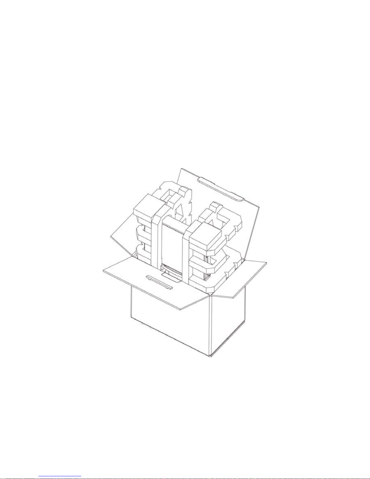
Unpacking
The product and accessories are packed in a paperboard carton. And it is wrapped by foam
padding for protection during shipping.
Page 17
- 10 -
2.2. Install Your POS System
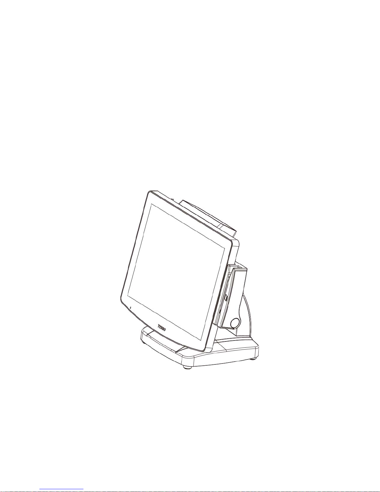
The product is a fully integrated POS System and easy for installation.
To install the POS System:
1. Place the product on the location.
2. Plug the AC power cord to the POS system
3. Connect the optional peripherals to the POS (for example: Mouse, Keyboard, and Barcode
Scanner.)
4. Plug the AC power cord to the power source (for example: electrical outlet).
5. Turn on the switch of the Printer Unit and Customer Display (if pre-installed) and the other
optional peripherals.
6. Turn on the POS system.
Note:
Always install the POS system and the optional peripherals on a flat, clean and stable
location.
To prevent obstruction on the operator, reserve appropriate space for the POS system and
remove unnecessarily objects or items.
Page 18
- 11 -
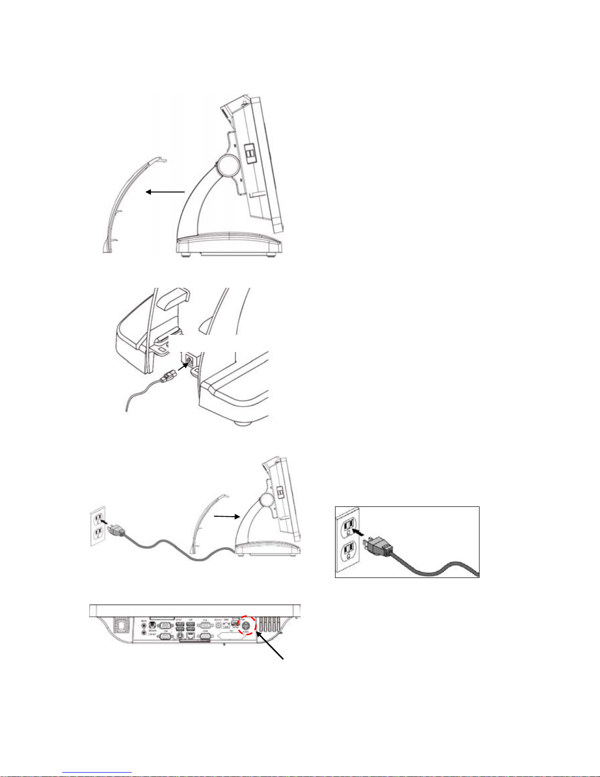
2.3. Plug AC Power Cord to the POS
a. Remove the base cover from the
base of the POS system.
b. The power adapter should be found
on the bottom of the base
(as image left illustrated).
Plug the supplied AC power cord into
the power adaptor.
c. Re-install the Back Cover and plug
the AC power cord in to the
AC outlet.
POS Unit
(Button I/O Ports)
d. Check the Power Adaptor connector
(pre-connected) is properly connect
to the Power Input (POS Unit)
Power Input
Base Cover
AC Power Cord
Power Adaptor
Base Cover
AC Outlet
AC Power Cord
Page 19
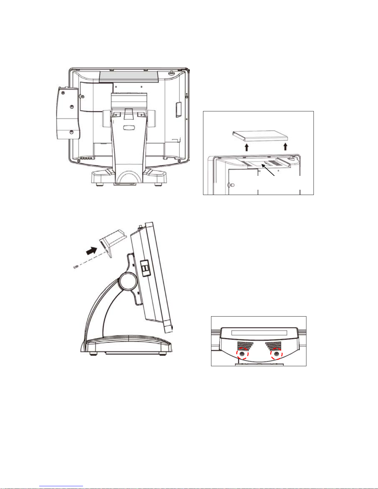
- 12 -
2.4. Replace Hard Disk
a. Remove the securing screw of the
HDD cover from the POS unit.
b. Remove the HDD Cover from the
POS unit.
Pull the HDD Module to the left to
detach it from the POS unit.
Disconnect the HDD Cable to
remove the HDD Module.
Remove the HDD Module
c. Loosen the securing screws to
remove the hard disk from the
bracket.
Then replace a new hard disk
d. Secure to the HDD module back to
the HDD cover
e. Re-install the HDD Cover (with new
HDD) back to the POS unit.
HDD Cover
(HDD Inside)
Securing Screws
Securing Screw
HDD Cover
(HDD Inside)
HDD Cover
(HDD Inside)
Securing Screws
Page 20
- 13 -
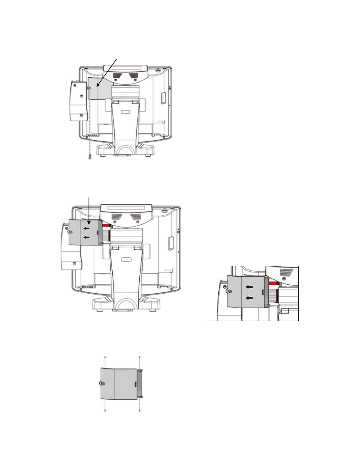
2.5. Install the Modular Customer Display (Optional)
a. Remove the Top Protective Cover.
There is a connector for the Modular
Customer Display.
b. Connect the connector of the Modular
Customer Display to the POS Unit.
c. Install the Modular Ccustomer Display
to the POS Unit.
d. .Secure the Securing Screws of
Modular Customer Display
Securing Screws
Note:
The Modular Customer Display is an Optional Accessory and is not included in the standard package.
Please contact your local representative for further information.
Top Protective Cover
Securing
Screws
X 2
Top Protective Cover
VFD Connector
Modular
Customer
Display
Page 21

- 14 -
2.6. Configuration of Modular Customer Display
There is a configuration utility to setup your pre-installed customer display
(refer to the configuration instruction manual for further information).
Please refer to the subfolder “\\Manual\POP-950” and examine the file
POP-950_VFD_Customer Display Config Manual_TYSSO_20130201.pdf before
configuration.
Page 22
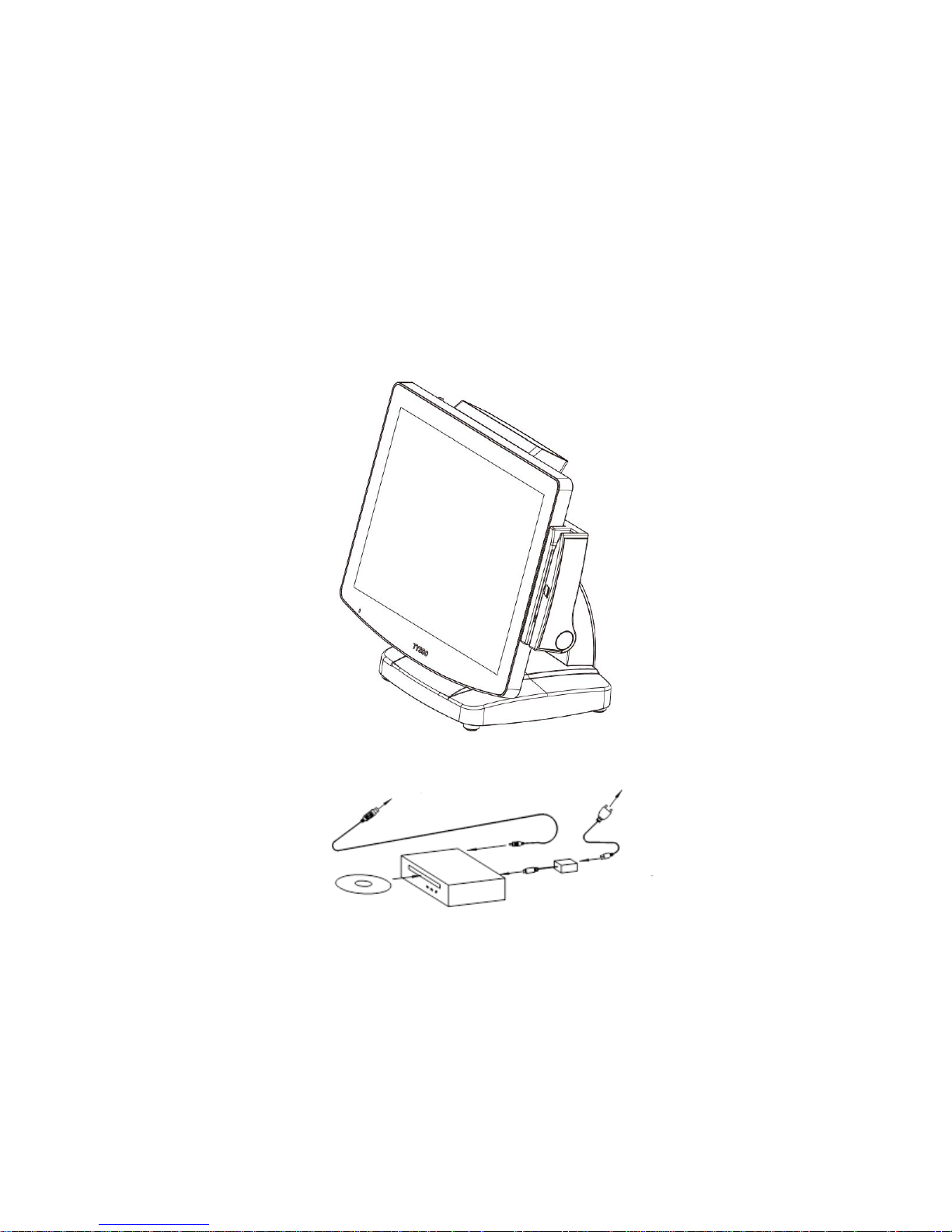
- 15 -
3. BIOS Setup
The product is compatible with POS Ready, Windows Families (98/2000/XP/7) and
Ubuntu Linux.
If the drivers are required, find the necessary files in the supplied disc.
Plug the AC power cord of the power adapter (CD/DVD-ROM DRIVE) to the power source.
Connect an external CD/DVD-ROM DRIVE to the POS system (as the figure below illustrated).
Insert the installation disc for the Operating System.
To Power Source
To USB Port
External CD/DVD-ROM Drive
Power Adaptor
Page 23

- 16 -
Overview
The BIOS is a program that takes care of the basic level of communication between the CPU and
peripherals. It contains codes for various advanced features found in this system board.
The BIOS allows you to configure the system and save the configuration in a battery-backed
CMOS so that the data retains even when the power is off. In general, the information stored in
the CMOS RAM of the EEPROM will stay unchanged unless a configuration change has been
made such as a hard drive replaced or a device added.
It is possible that the CMOS battery will fail causing CMOS data loss. If this happens, you need
to install a new CMOS battery and reconfigure the BIOS settings.
Note:
For the detailed technical information about the mainboard, please refer to the technical
document in the supplied Driver/Utility DVD.
The further configurations of the BIOS and the mainboard should only be reserved to the
qualified personnel only
Page 24

- 17 -
Default Configuration
Most of the configuration settings are either predefined according to the Load Optimal
Defaults settings which are stored in the BIOS or are automatically detected and
configured without requiring any actions. There are a few settings that you may need to
change depending on your system configuration.
Entering the BIOS Setup Utility
The BIOS Setup Utility can only be operated from the keyboard and all commands are
keyboard commands. The commands are available at the right side of each setup
screen.
The BIOS Setup Utility does not require an operating system to run. After you power up
the system, the BIOS message appears on the screen and the memory count begins.
After the memory test, the message “Press DEL to run setup” will appear on the screen.
If the message disappears before you respond, restart the system or restart the system
by pressing the <Ctrl> <Alt> and <Del> keys simultaneously.
Page 25

- 18 -
BIOS MENU Key Function
Keys
Function
Right and Left arrows
Moves the highlight left or right to select a menu.
Up and Down arrows
Moves the highlight up or down between submenu
and fields.
<Esc>
Exit to the BIOS Setup Utility.
+ (plus key)
Scrolls forward through the values or options of the
highlighted field.
- (minus key)
Scrolls backward through the values or options of the
highlighted field.
Tab
Select a field.
<F1>
Displays General Help
<Enter>
Press <Enter> to enter the highlighted submenu.
Scroll Bar
When a scroll bar appears to the right of the setup screen, it indicates that there are
more available fields not shown on the screen. Use the up and down arrow keys to
scroll through all the available fields.
Submenu
When ““appears on the left of a particular field, it indicates that a submenu which
contains additional options are available for that field. To display the submenu, move
the highlight to that field and press <Enter> to confirm the changes or selections.
Page 26
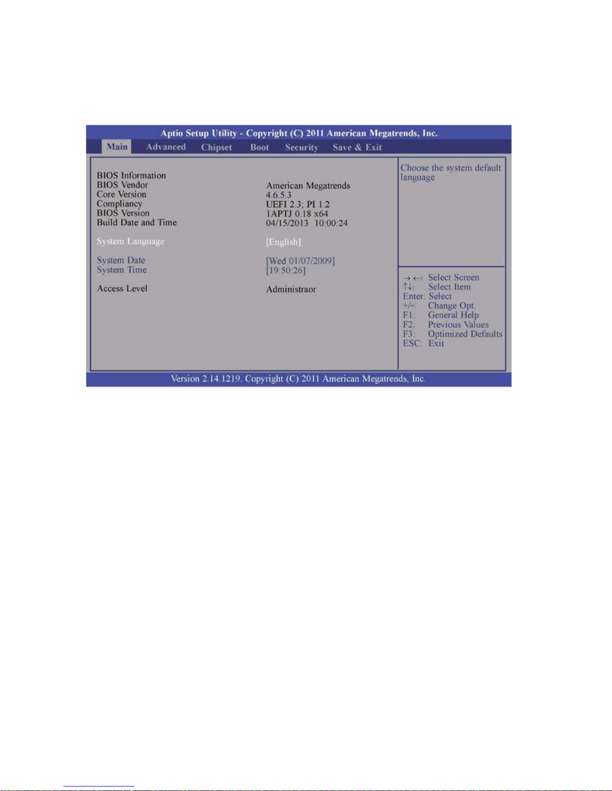
- 19 -
3.1. Main
The Main menu is the first screen that you will see when you enter the
BIOS Setup Utility
System Date
The date format is <day>, <month>, <date>, <year>.
<Day> displays a week day, from Sunday to Saturday.
<Month> displays the month, from January to December.
<Date> displays the date, from 1 to 31.
<Year> displays the year, from 1980 to 2099.
System Time
The time format is <hour>, <minute>, <second>.
The time is based on the 24-hour military-time clock.
For Example:
1 p.m. is 13:00:00.
<Hour> displays hours from 00 to 23.
<Minute> displays minutes from 00 to 59.
<Second> displays seconds from 00 to 59.
Page 27
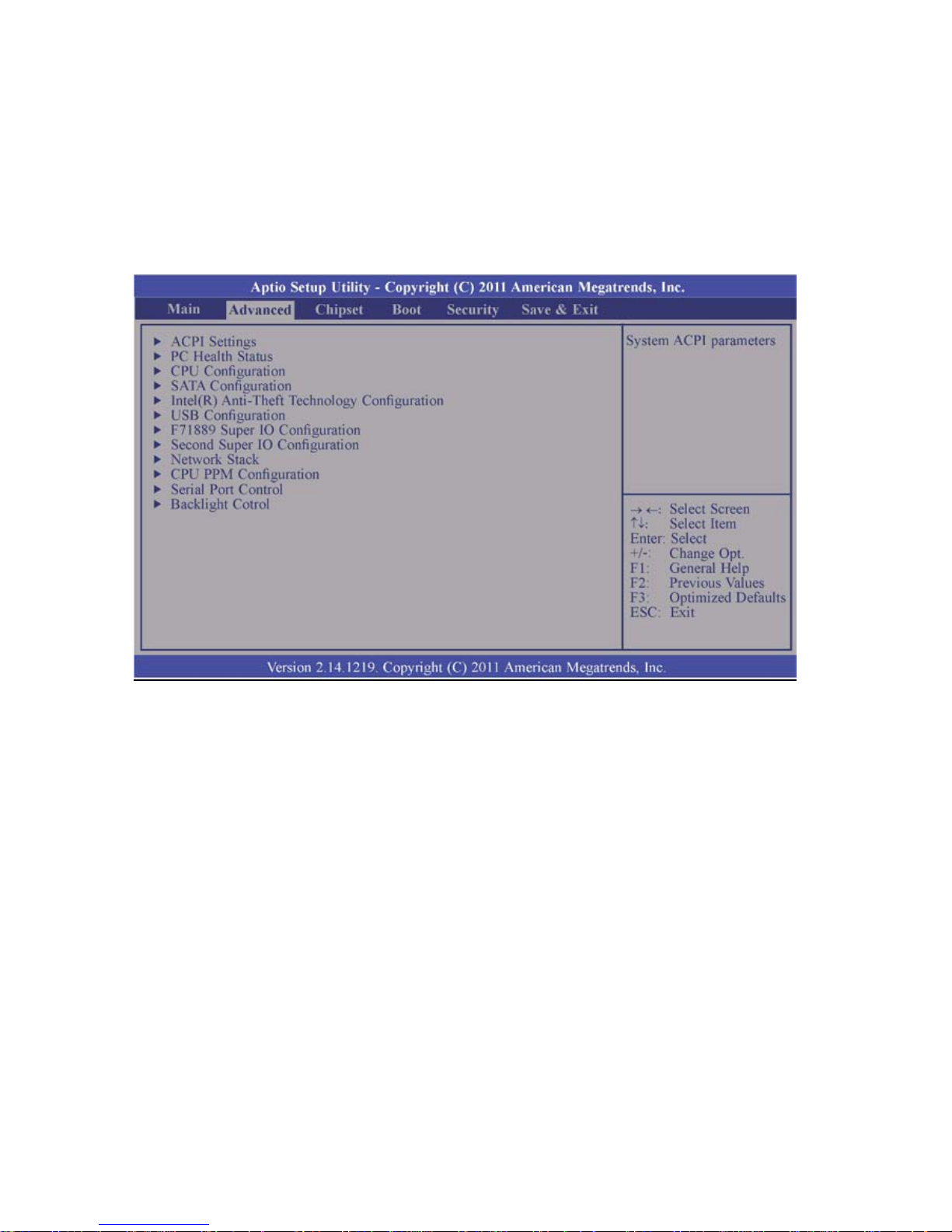
- 20 -
3.2. Advanced
The Advanced menu allows you to configure your system for basic operation.
Some entries are defaults required by the system board, while others, if enabled, will
improve the performance of your system or let you set some features according to your
preference.
Warning:
Setting incorrect field values may cause the system to malfunction.
Page 28
- 21 -
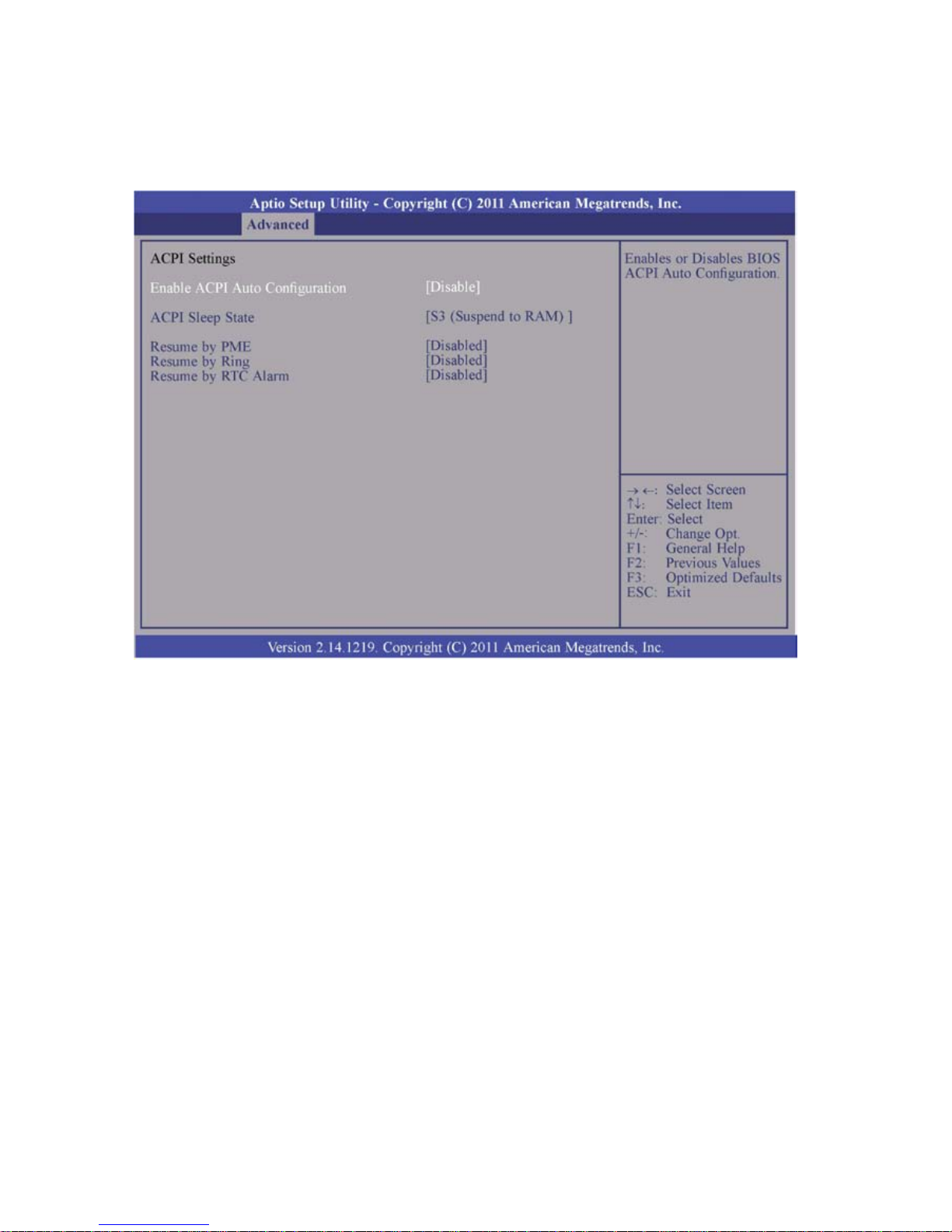
3.2.1. ACPI Power Management Configuration
This section is used to configure the ACPI Power Management.
ACPI Sleep State
Selects the highest ACPI sleep state the system will enter when the Suspend button
is pressed.
S1 (CSC) Enables the CPU stop Clock function.
S3 (STR) Enables the Suspend to RAM function.
Resume by PME
Enable this field to use the PME signal to wake up the system
(via PCI, PCIE and onboard LAN).
Resume by Ring
Enable this field to use the Ring signal to wake up the system.
Resume by RTC Alarm
When enabled, the system uses the RTC to generate a wakeup event.
Page 29
- 22 -
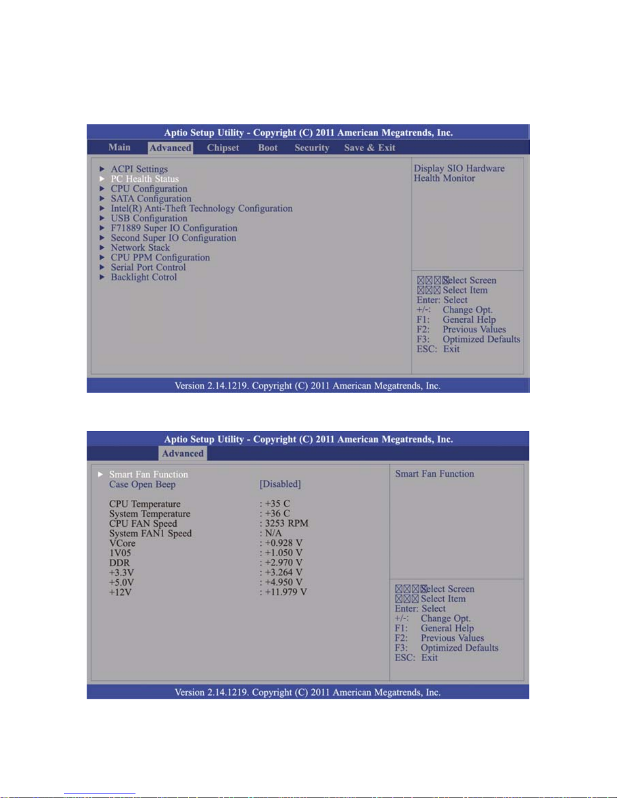
3.2.2. PC Health Status
This section displays the SIO hardware health monitor.
Move the cursor to “PC Health Status” and press <Enter> key to access the submenu.
The sub menu is as image bellow illustrated:
Page 30
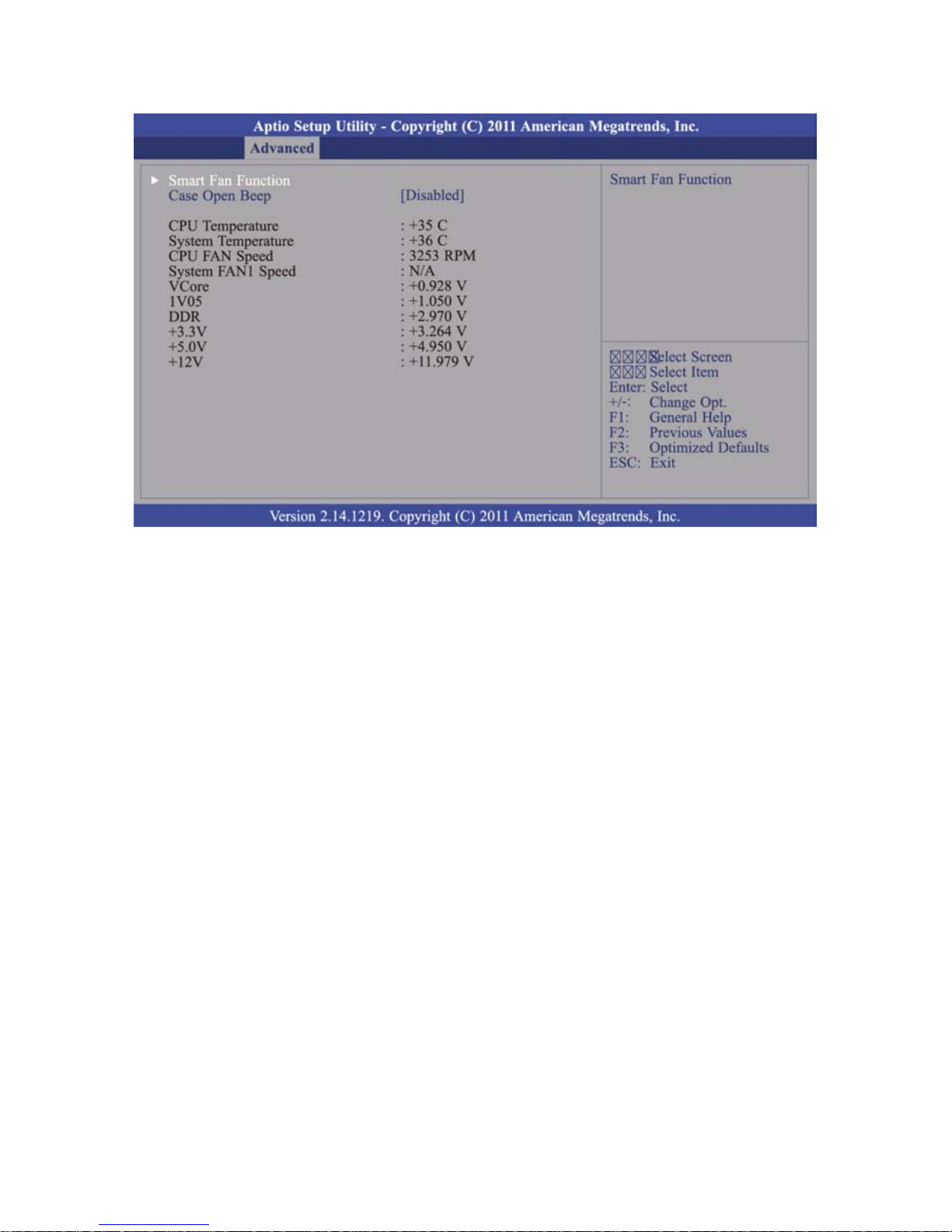
- 23 -
Smart Fan Function
CPU Smart Fan Control
When this feature is enabled, the CPU’s fan speed will rotate according to the CPU’s
temperature. The higher the temperature rises, the faster the speed of rotation.
Boundary 1
The temperature range is from 40 to 70.
Page 31

- 24 -
Tips: How to set the Smart Fan Function
1. Select the “PC Health Status“, and then press <Enter> key to continue.
2. Select the “Smart Fan Function“, and press <Enter> key to confirm.
Page 32

- 25 -
3. Select “CPU Smart Fan Control“.
4. Select “Enable“
Page 33

- 26 -
5. The function is enabled.
6. Select “Boundary 1” and press <Enter>.
The pop-up window indicates the selections (temperature range) from 40 to 70.
When this feature is enabled, the CPU’s fan speed will rotate faster according to the
CPU’s temperature.
Page 34

- 27 -
7. After the temperature is set, switch the BIOS screen to the “Save & Exit” page.
8. Select “Yes“ and then press <Enter> key to finish the setting of Smart Fan function.
Page 35

- 28 -
3.2.3. CPU Configuration
This section is used to configure the CPU. It will also display the detected CPU
information.
Hyper-threading
Enable this field for Windows XP and Linux which are optimized for
Hyper-Threading technology. Select disabled for other OS not optimized for
Hyper-Threading technology. When disabled, only one thread per enabled core is
enabled.
Active Processor Cores
Number of cores to enable in each process or package.
Limit CPUID Maximum
The CPUID instruction of some newer CPUs will return a value greater than 3.
The default is "Disabled" because this problem does not exist in the Windows series
operating systems. If you are using an operating system other than Windows, this
problem may occur.
To avoid this problem, enable this field to limit the return value to 3 or less than 3.
Intel Virtualization Technology
When this field is set to Enabled, the VMM can utilize the additional hardware
capabilities provided by Vander pool Technology.
Page 36

- 29 -
3.2.4. SATA Configuration
This section is used to set the options of SATA device.
SATA Controller(s)
This field is used to enable or disable the Serial ATA channels.
SATA Mode Selection
This field is used to determine how SATA controller(s) operates.
IDE Mode
This option configures the Serial ATA drives as Parallel ATA storage devices.
AHCI Mode
This option allows the Serial ATA devices to use AHCI (Advanced Host Controller
Interface).
RAID Mode
This option allows you to create RAID or Intel Matrix Storage configuration on Serial
ATA devices.
SATA Test Mode
This field is used to enable or disable the Serial ATA test mode.
Page 37

- 30 -
If AHCI or RAID mode is selected in the SATA Mode Selection, it will display the following
information:
Serial ATA Port 0 to Serial ATA Port 3
These fields are used to configure the connected SATA devices.
Aggressive LPM Support
Enable PCH to aggressively enter link power state.
Alternate ID
Report Alternate Device ID.
Page 38

- 31 -
3.2.5. Intel Anti-Theft Technology Configuration
This section is used to disable Intel Anti-Theft for users to be allowed to login into the
platform. It is strict for testing only. Intel Anti-Theft Services in ME is not disabled.
Intel Anti-Theft Technology
Enable or Disable the Intel Anti-Theft in BIOS for testing only.
Intel Anti-Theft Technology Rec
Setting the number of attempted recovery time will be allowed.
Page 39

- 32 -
3.2.6. USB Configuration
This section is used to configure USB parameters.
Legacy USB Support
Enabled
Enable legacy USB.
Auto
Disables support for legacy when no USB devices are connected.
Disabled
Keep USB devices available only for EFI applications.
EHCI Hand-off
This is a workaround for OS that does not support EHCI hand-off. The change of
EHCI ownership should be claimed by the EHCI driver.
USB Mass Storage Driver Support
Enables or disables the support for USB mass storage driver.
USB transfer time-out
Select the time-out value for Control, Bulk and Interrupt transfers.
Device reset time-out
Select the USB mass storage device start unit command timeout.
Device power-up delay
Maximum time the device will take before it properly reports itself to the
Host Controller. “Auto” uses default value: for a Root port (100 ms), for a Hub port
the delay is taken from Hub descriptor
Page 40

- 33 -
3.2.7. F71889 Super IO Configuration
This section is used to configure the I/O functions supported by the onboard
Super I/O chip.
Restore AC Power Loss
Off
When power returns after an AC power failure, the system’s power is off. You must
press the Power button to power-on the system.
On
When power returns after an AC power failure, the system will automatically
power-on.
Last State
When power returns after an AC power failure, the system will return to the state
where you left off before power failure occurs.
If the system’s power is off when AC power failure occurs, it will remain off when
power returns.
If the system power is turned on when AC power failure occurs, the system will
power-on when power returns.
WatchDog Timer
Enables or disables Super I/O utilizes timer.
Page 41

- 34 -
Serial Port 1 Configuration to Serial Port 2 Configuration
Serial Port
Enable or disable the serial port.
Change Settings
Select the IO/IRQ setting for the super I/O device.
Device Mode
Change the serial port mode. Select the “High Speed“ or “Normal Mode“.
Page 42

- 35 -
Parallel Port Configuration (Reserved)
Note:
The Parallel port is only avail for the customized version mainboard
(with parallel port connector mounted).
For specific applications that require the parallel port, please contact the trained
personnel prior to the configuration.
Parallel Port
Enables or Disables the Parallel Port (LPT/LPTE).
Change Settings
Select the IO/IRQ setting for the I/O device.
Device Mode
Change the printer port mode.
Page 43

- 36 -
3.2.8. Second Super IO Configuration
This section is used to configure the I/O functions supported by the onboard
Super I/O chip.
Serial Port 3 to Serial Port 6 Configurations
Port 3
Page 44

- 37 -
Port 4
Port 5
Page 45

- 38 -
Port 6
Serial Port
Enable or disable the serial port.
Change Settings
Select the IO/IRQ setting for the super I/O device.
Device Mode
Change the serial port mode. Select either the “High Speed “or “Normal Mode“.
Page 46

- 39 -
3.2.9. Network Stack
This section configures settings relevant to the network stack.
Page 47

- 40 -
Network Stack
Enable or disable UEFI network stack.
Ipv4 PXE Support
When enabled, Ipv4 PXE boot supports.
When disabled, Ipv4 PXE boot option will not be created.
Ipv6 PXE Support
When enabled, Ipv6 PXE boot supports.
When disabled, Ipv6 PXE boot option will not be created.
Page 48

- 41 -
3.2.10. CPU PPM Configuration
EIST
This field is used to enable or disable the Intel Enhanced Speed Step Technology.
CPU C3 Report
Enabled/Disabled CPU C3 (ACPI C2) report to OS.
CPU C6 Report
Enabled/Disabled CPU C6 (ACPI C3) report to OS.
Config Top Lock
Lock the Config TDP control register.
Long Duration Power Limit
Long duration power limit in Watts, 0 means use factory default.
Long Duration Maintained
Time window which the long duration power is maintained.
Short Duration Power Limit
Short duration power limit in Watts, 0 means use factory default.
ACPI T State
Enable or disable ACPI T state support.
Page 49

- 42 -
3.2.11. Serial Port Control
This section is used to select the power of serial COM ports.
COM 1, COM 2, COM 4 and COM 6 Select
Select the power voltage of serial COM ports: 5V, 12V or RI.
Page 50

- 43 -
3.2.12. Backlight Control
This section is used to select the lightness of backlight.
Backlight
Step1 is the darkest level.
Step8 is the brightest level.
Page 51

- 44 -
3.3. Chipset
This field is used to configure the functions of relevant chipset.
Page 52

- 45 -
3.3.1. PCH-IO Configuration
Wake on LAN
Enable this field to wake up the system via the onboard LAN or via a LAN card that
supports the function of remote wake up.
After G3
Select the state of AC power when the power is re-applied after a power failure.
Power Off / WOL
Power-on the system via WOL after G3.
Power On
Power-on the system after G3.
Page 53

- 46 -
PCI Express Configuration
PCI Express Clock Gating
Enable or disable PCI Express Clock Gating for each root port.
PCI Express Root Port 1 to PCI Express Root Port 3
Control the PCI Express Root Port 1 ~ Port 3.
Page 54

- 47 -
USB Configuration
XHCI Pre-Boot Driver
Enable or disable the support for XHCI Pre-Boot Driver.
XHCI Mode
Select the mode to operate the XHCI controller.
EHCI 1 and EHCI 2
EHCI 1 and EHCI 2 control the USB EHCI (USB 2.0) functions.
One of them must always be enabled.
Page 55

- 48 -
PCH Azalia Configuration
Azalia
Select the control detection of the Azalia device.
Page 56

- 49 -
3.3.2. System Agent (SA) Configuration
Page 57

- 50 -
Graphics Configuration
Primary Display Spread is controlled by BIOS.
Auto: When the system boots, it will auto detects the display device.
IGFX: When the system boots, it will first initialize the onboard VGA.
PEG: When the system boots, it will first initialize the PCI Express x16 graphics
card.
DVMT Total Gfx Mem
This field is used to select the DVMT5.0 total graphics memory size used by the
Internet Graphics device.
Page 58

- 51 -
LCD Control
Primary IGFX Boot Display and Secondary IGFX Boot Display
The options are VBIOS Default, CRT, and LVDS.
LCD Panel Type
This field is used to select the type of LCD panel used by the
internal graphics device.
Type 3: 1024x768 18bit for 15’’ LED Type Panel
Type 12: 1024x768 24bit for 15’’ CCFL Type Panel
Type 13: 1280x1024 48bit for 17’’ CCFL Type Panel
Spread Spectrum Clock Chip
This field is used to select the clock control of spread.
Hardware
Spread is controlled by chip.
Software
Primary Display Spread is controlled by BIOS.
Page 59

- 52 -
NB PCIe Configuration
Enabled PEG
Enables or disables the PEG.
Memory Configuration
Page 60

- 53 -
3.4. Boot
Setup Prompt Timeout
Select the number of seconds to wait for the setup activation key. 65535(0xFFFF)
denotes indefinite waiting.
Bootup NumLock State
This allows you to determine the default state of the numeric keypad. By default, the
system boots up with NumLock on wherein the function of the numeric keypad is the
number keys. When set to “Off”, the function of the numeric keypad is the arrow
keys.
Quiet Boot
Enable or disables the quiet boot function.
Fast Boot
Enable or disable boot with initialization of a minimal set of devices required to
launch active boot option. Has no effect for BBS boot options.
Skip VGA When it is enabled, BIOS will skip EFI VGA driver.
Skip USB When it is enabled, USB devices will not be available after OS boot.
When it is disabled, USB devices will be available before OS boot
Skip PS2 When it is enabled, PS2 devices will be skipped.
GateA20 Active
Upon Request.
GA20 can be disabled in BIOS services.
Page 61

- 54 -
Always
Disabling GA20 is not allowed; this option is useful when any RT code is executed
above 1 MB.
Option ROM Messages
This field is used to set the display mode of Option ROM.
INT19 Trap Response
BIOS reaction on INT19 trapping by Option ROM:
Immediate
Execute the trap right away.
Postponed
Execute the trap during legacy boot.
Boot Option #1
Set the order of the system boot.
Page 62

- 55 -
Tips: How to set the Boot Option
1. Select “Boot Option #1“ , and then press <+> to make it be the prior boot option
2. Switch to the “Save & Exit” page. Select “Yes” and then press <Enter> key to
finish the setting of Boot Option.
Page 63

- 56 -
Hard Driver BBS Priorities
Set the order of the legacy devices in this group.
CSM Parameters
Launch Storage OpROM policy
Control the execution of UEFI and legacy storage OpROM.
Page 64

- 57 -
3.5. Security
Administrator Password
Set the administrator password.
User Password
Set the user password.
HDD Security Configuration (reserved)
HDD0: Hitachi HTS5: Set the HDD password.
Note:
This function is functional only for some models of HITACHI’s hard disk drivers.
Please contact the personnel of technical support for further information.
Page 65

- 58 -
3.6. Save & Exit
Save Changes and Reset
To save the changes, select this field and then press <Enter>. A dialog box will
appear. Select “Yes” to reset the system after saving all changes made.
Discard Changes and Reset
To discard the changes, select this field and then press <Enter>.
A dialog box will appear.
Select “Yes” to reset the system setup without saving any changes.
Restore Defaults
To restore and load the optimized default values, select this field and then press
<Enter>. A dialog box will appear. Select “Yes” to restore the default values of all the
setup options.
Save as User Defaults
To save changes done so far as user defaults, select this field and then press
<Enter>. A dialog box will appear. Select “Yes” to save values as user default."
Restore User Defaults
To restore user default to all the setup options, select this field and then press
<Enter>. A dialog box will appear. Select “Yes” to restore user default.
Launch EFI Shell from file system device
Attempts to launch EFI shell application (Shellx64.efi) from one of the available file
system devices.
Page 66

- 59 -
3.7. Updating the BIOS
To update the BIOS, you will need the new BIOS file and a flash utility, AFUDOS.EXE.
Please contact technical support or your sales representative for the files.
To execute the utility, type:
A:> AFUDOS BIOS_File_Name /b /p /n
then press <Enter>.
Page 67

- 60 -
Page 68

- 61 -
4. Install the Support Softwares of POS Terminal
Please place the supplied disc into the CD/DVD-ROM drive.
Browse the DISC and open the folders required to install the driver(s).
Double click the folder “Driver & Utility” to access the folder.
There are categorized folders for POS Terminal, Peripherals and Touch Screen drivers.
To install the drivers of POS terminal:
a. Double click the folder “POS Terminal Driver”
b. There are subfolders as image below illustrated.
Please access the folder “\Core I \” for the drivers required.
Page 69

- 62 -
c. There are subfolder of drivers and utilizes for the operating system.
User may double-click the icon “Setup”
to initiate the Menu and install the
appropriate drivers or utilities
Page 70

- 63 -
d. Move the cursor to the Utility Menu and click to install the software required
※ Please refer to the manual of the mainboard for detailed instructions
(Driver & Utility\POS Terminal Driver\Core i\MANUAL)
Page 71

- 64 -
4.1. Microsoft .NET Framework 3.5 (for Windows XP only)
Click “Microsoft .NET Framework 3.5” on the utility menu.
Note:
Before installing Microsoft .NET Framework 3.5, make sure you have updated your
Windows XP operating system to Service Pack 3.
There is application software or peripherals/optional devices require the different
version of Microsoft .Net Framework.
Please consult the technical support of the providers for further information.
To setup the .NET Framework:
a. Read the license agreement carefully.
Click “I have read and accept the terms of the License Agreement” then click Install.
Page 72

- 65 -
b. Setup is now installing the driver
c. Setup completed. Click Exit to close the program.
Page 73

- 66 -
4.2. Intel Chipset Software Installation Utility
The Intel Chipset Software Installation Utility is used for updating Windows® INF files so that the
Intel chipset can be recognized and configured properly in the system.
To install the utility, click “Intel Chipset Software Installation Utility” on the menu.
a. Setup is ready to install the utility. Click “Next” to continue
b. License agreement. Click “Yes” to continue
Page 74

- 67 -
c. Readme file information (for more installation tips).
Click “Next” to continue or click “Cancel” to abort the installation.
d. Setup is completed.
It’s recommended to restart the system after the driver is installed.
Click “Finish” to restart the computer.
Page 75

- 68 -
4.3. Intel HD Graphics Driver
To install the driver, click “Intel HD Graphics Drivers” on the utility menu.
a. Setup is now ready to install the graphics driver. Click Next tip continue.
By default, the “Automatically run WinSAT and enable the Windows Aero desktop theme” is
enabled. With this enabled, after installing the graphics driver and the system rebooted, the
screen will turn blank for 1 to 2 minutes (while WinSAT is running) before the Windows Vista
desktop appears. The “blank screen” period is the time Windows is testing the graphics
performance.
Page 76

- 69 -
b. License agreement. Click “Yes” to continue.
c. Readme File Information.
Go through the readme document for system requirements and installation tips then
click “Next” to continue.
Page 77

- 70 -
d. Setup is now installing the driver.
Click “Next” to continue.
e. Click “Yes, I want to restart this computer now” then click “Finish” to complete the installation.
Restart the system and then the new software installation will take effect.
Page 78

- 71 -
4.4. LAN Driver
To install the driver, click “Realtek LAN Drivers” on the menu.
a. Click “Next” to start installing the driver to the computer.
b. Click “Install” to continue the setting process
Page 79

- 72 -
c. Click “Finish” to finish the installation
Page 80

- 73 -
4.5. Audio Driver
a. Click “Next” to start installing the driver to the computer.
b. The audio driver is successfully installed.
It’s recommended to restart the system after the driver is installed.
Click “Yes, I want to restart my computer now” then click “Finish” to restart the computer.
Restarting the system will allow the new software installation to take effect.
Page 81

- 74 -
5. Install the Touch Screen Driver
Please place the supplied disc into the CD/DVD-ROM drive.
Browse the disc and double click the folder “Driver & Utility” to access the folder.
There are categorized folders for POS Terminal, Peripherals and Touch Screen drivers.
Page 82

- 75 -
5.1. Install the Driver of Resistive Type Touch Panel
To install the drivers of Resistive Touch Panel:
a. Double click the folder “Touch Driver” to access the subfolder.
b. There are drivers of Resistive type and SAW type touch screen.
To install the driver for Resistive type,
select (double click) the folder “Resistive Touch” to start installation.
c. Select the folder “Resistive Touch(EETI) Core i and D2550 MB”
and access the subfolders.
d. Select the subfolder “Windows” for Windows families operating system
e. Select the subfolder according to the operating system installed.
(for example: select “Win XP” for the Windows XP 32-bit version)
f. Double click the file “Setup.EXE” to start the installation.
Page 83

- 76 -
g. Click “Next” to start the installation.
h. License Agreement.
Click “I accept the terms of the license agreement” and click “Next” to continue.
Page 84

- 77 -
i. Setup Type: PS/2 Interface (reserved).
This is reserved for Extra PS/2 Interface version only.
Leave the check box UNMARKED.
Click “Next” to continue.
j. Setup Type: RS-232 Interface (reserved):
This is reserved for RS-232 Interface version only.
Leave the check box UNMARKED.
Click “Next” to continue.
Page 85

- 78 -
k. Setup Type: Calibration after system reboot:
Click the checkbox “None” and click “Next” to continue.
l. There is a pop-up dialogue.
Click “Ok” to continue.
Page 86

- 79 -
m. Setup Type: Support Multi-monitor System:
Click the checkbox “Support Multi-Monitor System” and click “Next” to continue.
n. Choose Destination Location:
Click “Browse to change the different destination folder.
Note:
It’s recommended to use the defined location and install the driver.
Click “Next” to continue.
Page 87

- 80 -
o. Select Program Folder:
Use the pre-defined setting and click “Next” to continue.
p. Create Shortcut on the desktop:
Click the checkbox and click “Next” to continue.
Page 88

- 81 -
q. Now the software is installing to the system.
Page 89

- 82 -
r. 4-Point Calibration.
Click “Yes” to perform touch screen calibration.
s. Touch the first calibration mark on the edge of the screen.
There is a beep sound to indicate the point is calibrated.
Proceed to the next mark and perform all 4 calibration points to complete the calibration.
t. Installation completed. There is an icon on the screen for quick launch.
Note:
It’s recommended to reboot the system after installation is completed.
Page 90

- 83 -
5.2. Touch Screen Calibration (Resistive Type)
After the driver is installed to the system, there is a shortcut on the desktop for touch screen
Calibration. User can re-configure the touch screen by initiating the utility.
To calibrate the touch screen:
a. Double click the icon to access the utility.
b. User can perform 4-point-calibration by selecting the function “4 Points Calibration”.
Click “OK” to continue.
Page 91

- 84 -
c. Tap the calibration mark on the bottom-left to complete the first calibration point.
There is a beep sound to indicate the point is calibrated.
Proceed to the next mark and complete all calibration points
d. The calibration is completed; Click “OK” to continue.
Page 92

- 85 -
Tips: Advanced 9-point/25-point Calibration
There are advanced 9-point calibration and 25-point calibration for more accurate
calibration demands.
a. Access “Setting” submenu, and select “Linearization Style” (9 Points or 25 Points) to
calibrate your touch screen.
Page 93

- 86 -
b. Access “Tools” submenu, and select “Linearization” to calibrate your touch screen.
c. Tap the calibration mark on the bottom-left to complete the first calibration point.
There is a beep sound to indicate the point is calibrated.
Proceed to the next mark and complete all calibration points (9 Points or 25 Points).
Page 94

- 87 -
6. Peripherals Test
The POS terminal is equipped with mainstream interfaces for the connection of peripherals and
devices. If the POS is equipped with optional peripherals (for example: Wi-Fi module, magnetic
stripe card reader, customer display, or a cash drawer). Please install the driver or perform the
tests prior or to the POS system is operational.
Note:
For more information relating to the other optional peripherals, please contact the local
representatives or technical support personnel of the nearest providers.
Please place the supplied disc into the CD/DVD-ROM drive.
Browse the disc and double click the folder “Driver & Utility” to access the folder.
There are categorized folders for POS Terminal, Peripherals and Touch Screen drivers.
Select “Peripherals” to access the subfolders.
The subfolders of peripherals are as follows:
Select (double click) the folder for the peripheral required.
Page 95

- 88 -
6.1. Install the Wi-Fi Driver (Optional)
There are categorized subfolders for POS Peripherals.
Select “WiFi” to access the subfolders.
a. Open the folder “LR802UKN3(USB)”to access the subfolders:
b. Open the folder to find the appropriate driver.
c. Access the subfolder and double click the icon to install the driver.
d. Click “Yes” to accept the terms of License Agreement and continue.
Page 96

- 89 -
e. Select “Install driver only” and click “Next” to continue.
f. Click “Install” to begin Installation.
Page 97

- 90 -
g. The Wi-Fi driver is successfully installed.
Click “Finish” to complete and exit the Wizard
Note:
To access the wireless network and initiate the connection, please refer to the service provider
for further information.
Page 98

- 91 -
6.2. Test Your Magnetic Stripe Card Reader(MSR) and i-Button Module
a. Execute Start >> All Programs >> Accessories >>Notepad.
b. MSR Test:
Swipe a card through the reader and the information will be displayed on the window
Page 99

- 92 -
c. i-Button Test:
Attach the i-button to the reader and the information will be displayed on the window
Page 100

- 93 -
6.3. Test Your Customer Display
There are categorized subfolders for POS Peripherals.
a. Select (double click) the subfolder “Customer Display”.
b. There are two folders for LCD type Customer Display (DSP) and
Vacuum Fluorescent type Display (VFD).
Select the folder by the Customer Display installed.
c. Select the subfolder “Test Utility”.
d. Double click the file “BREAKOUT” to initiate the program.
 Loading...