

Page 1
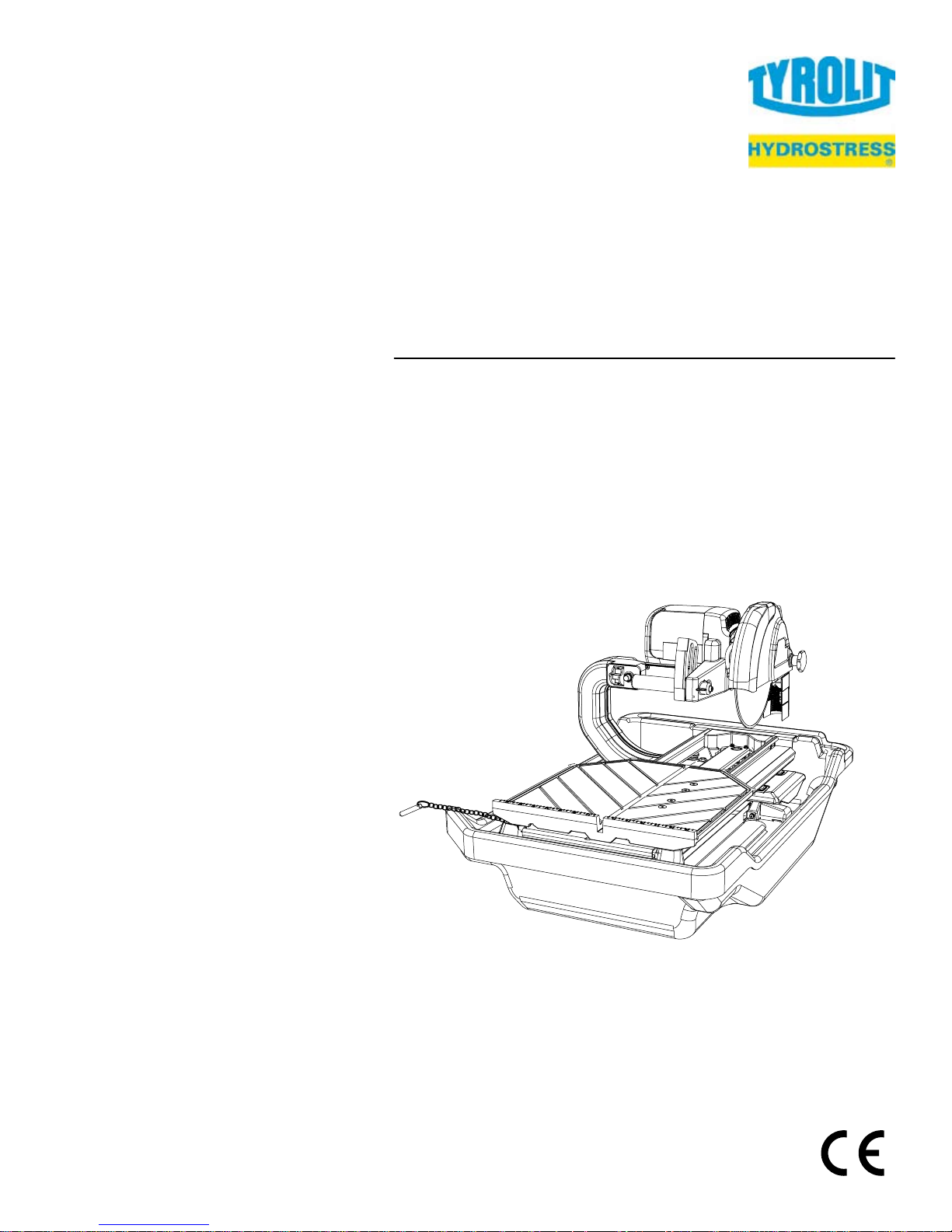
Operating Manual
Spare Parts List
Wet Tile Saw
TTE250
Index / Indice «001»
10984578 EN / 18.05.2009
Page 2

Manufacturer's address:
TYROLIT Hydrostress AG
Witzbergstrasse 18
CH-8330 Pfäffikon
Switzerland
Tel.
+41
(0)44 952 18 18
Fax +41
(0)44 952 18 00
www.
tyrolit
.com
TYROLIT Hydrostress AG reserves the right to make technical changes without prior notice.
Copyright © 2005 TYROLIT Hydrostress AG, CH-8330 Pfäffikon ZH, Switzerland
All rights rese
rved, in particular copyrighting and translating rights.
Printing of this operating manual, including extracts from it, is prohibited. No parts of it may be repr
o-
duced in any form or processed using electronic systems, duplicated or disseminated without th
e wri
t-
ten permission of TYROLIT Hydrostress AG.
Page 3

TABLE OF CONTENTS
PAGE
I. GENERAL SAFETY RULES FOR ALL POWER TOOLS . . . . . . . . . . . . . . . . . . . . . . . . . . . . . . . . . . . . . . 3
II. SYMBOLS . . . . . . . . . . . . . . . . . . . . . . . . . . . . . . . . . . . . . . . . . . . . . . . . . . . . . . . . . . . . . . . . . . . . . . . . . . 4
III. FEATURES . . . . . . . . . . . . . . . . . . . . . . . . . . . . . . . . . . . . . . . . . . . . . . . . . . . . . . . . . . . . . . . . . . . . . . . . . 5
IV. SPECIFICATIONS . . . . . . . . . . . . . . . . . . . . . . . . . . . . . . . . . . . . . . . . . . . . . . . . . . . . . . . . . . . . . . . . . . . . 5
V. GETTING TO KNOW YOUR SAW . . . . . . . . . . . . . . . . . . . . . . . . . . . . . . . . . . . . . . . . . . . . . . . . . . . . . . . 6
VI. BLADE INSTALLATION. . . . . . . . . . . . . . . . . . . . . . . . . . . . . . . . . . . . . . . . . . . . . . . . . . . . . . . . . . . . . . . . 7
VII. SAFE OPERATING PRACTICES FOR TILE SAW . . . . . . . . . . . . . . . . . . . . . . . . . . . . . . . . . . . . . . . . 7-10
VIII. USING THE CUTTING TABLE . . . . . . . . . . . . . . . . . . . . . . . . . . . . . . . . . . . . . . . . . . . . . . . . . . . . . . . . . 10
XIX. CARE AND MAINTENANCE . . . . . . . . . . . . . . . . . . . . . . . . . . . . . . . . . . . . . . . . . . . . . . . . . . . . . . . . .11-13
X. CUTTING DEPTH . . . . . . . . . . . . . . . . . . . . . . . . . . . . . . . . . . . . . . . . . . . . . . . . . . . . . . . . . . . . . . . . . . . 14
XI. REPLACEMENT PART LISTS. . . . . . . . . . . . . . . . . . . . . . . . . . . . . . . . . . . . . . . . . . . . . . . . . . . . . . . 14-18
XII. ACCESSORIES. . . . . . . . . . . . . . . . . . . . . . . . . . . . . . . . . . . . . . . . . . . . . . . . . . . . . . . . . . . . . . . . . . . . . 19
XIII. HOW TO ORDER PARTS . . . . . . . . . . . . . . . . . . . . . . . . . . . . . . . . . . . . . . . . . . . . . . . . . . . . . . . . . . . . . 20
XIV. ELECTRICAL MOTOR SPECIFICATION . . . . . . . . . . . . . . . . . . . . . . . . . . . . . . . . . . . . . . . . . . . . . . . . . 21
XV. TROUBLESHOOTING. . . . . . . . . . . . . . . . . . . . . . . . . . . . . . . . . . . . . . . . . . . . . . . . . . . . . . . . . . . . . . . . 22
Page 4

i. GENERAL SAFETY RULES FOR ALL POWER TOOLS
WARNING!
Read all instructions. As with all machinery there are certain hazards involved with operation and
use of the machine. The following basic safety precautions should be followed at all times to reduce the risk of fire,
electric shock and serious personal injury to you or others. Keep these important operating instructions with this
product.
1. Know your power tool - read owner’s/operator’s manual carefully. Learn its applications and limitations as well as the
specific potential hazards unique to this tool.
2. Keep guards in place - and in working order.
3. Ground all tools - if tools are equipped with three prong plug, it should be plugged into a three-hole electrical
receptacle. If an adapter is used to accommodate a two-prong receptacle, the adapter lug must be attached to a
known ground. Never remove the third prong.
4. Remove wrenches - Form a habit of checking to see that adjusting wrenches are removed from tool before turning it
“on”.
5. Keep work area clean. Cluttered areas and benches invite accidents.
6. Do not use in dangerous environment. Do not use power tools in damp or wet locations, or expose them to rain.
Keep work area well lighted. Do not use tool in the presence of flammable liquids or gasses.
7. Keep children and visitors away. All children and visitors should be kept at a safe distance from work area.
8. Make workshop childproof with padlocks, master switches or by removing starter keys.
9. Do not force tool. It will do the job better and be safer at the rate for which it was designed.
10. Use right tool. Do not force tool or attachment to do a job for which it was not designed.
11. Wear proper apparel. Do not wear loose clothing, gloves, neckties, rings, bracelets or other jewelry that may get
caught in moving parts. Non-slip footwear is recommended. Wear protective hair covering to contain long hair.
Always use safety glasses. Wear safety glasses at all times. Everyday eyeglasses only have impact
12.
resistant lenses; they are not safety glasses. Use face or dust mask if cutting operation is dusty, and ear protectors
(plugs or muffs) during extended periods of operation.
13. Do not overreach. Keep proper footing and balance at all times.
14. Maintain tools in top condition. Keep tools sharp and clean for best and safest performance. Follow instructions for
lubricating and changing accessories. Inspect tool cords periodically and if damaged, have repaired by authorized
service facility.
15. Disconnect tools. When not in use, before servicing, and when changing accessories, such as blades, bits, cutters.
16. Avoid accidental starting. Make sure switch is in “off” position before plugging in power cord.
17. Use recommended accessories only. Consult the owner’s manual for recommended accessories. The use of
improper accessories may cause risk of injury to persons.
18. Never stand on tool. Serious
19. Check Damaged Parts. Before further use of the tool, a guard or other part that is damaged should be carefully
checked to ensure that it will operate properly and perform it’s intended function. Check for alignment of moving
parts, binding of moving parts, breakage of parts, mounting, and any other conditions that may affect it’s operation.
A guard or part that is damaged should be properly repaired or replaced.
injury could occur if the tool is tipped or if the cutting tool is accidentally contacted.
20. Never leave tool running unattended. Turn power “off”. Do not leave tool until it comes to a complete stop.
– 3 – – 4 –
Page 5
21. Extension cords. Make sure your extension cord is in good condition. When using an extension cord, be sure to use
one heavy enough to carry the current your product will draw. An undersized cord will cause a drop in line voltage
resulting in loss of power and overheating. Extension cord tables
depending on cord length and nameplate ampere rating. If in doubt, use the next heavier gage. The smaller the
gage numbers the heavier the cord.
22. Do not abuse cord. Never carry tool by cord or pull it to disconnect from receptacle, Keep cord from heat, oil, and
sharp edges.
23. Guard against electric shock. Prevent body contact with grounded surfaces. For example, pipes, radiators, ranges
and refrigerator enclosures.
24. Outdoor use extension cords. When tool is used outdoors, use only extension cords intended for use outdoors and
so marked.
25. Stay alert. Watch what you are doing. Use common sense. Do not operate tool when you are tired.
26. Drugs, alcohol, medication. Do not operate tool while under the influence of drugs, alcohol or any medication.
27. Store idle tool. When not in use, tool should be stored in a dry and locked place, out of reach of children.
Sawing generates dust. Excessive airborne particles may cause irritation to eyes, skin and
WARNING!
respiratory tract. To avoid breathing impairment always employ dust controls and protection suitable to the material
being saw. Diamond blades improperly used are dangerous. Comply with safety regulations covering speed, safety
guards, flanges, mounting procedures, general operating rules, handling, storage and general machine condition.
(refer to page 21) show the correct size to use
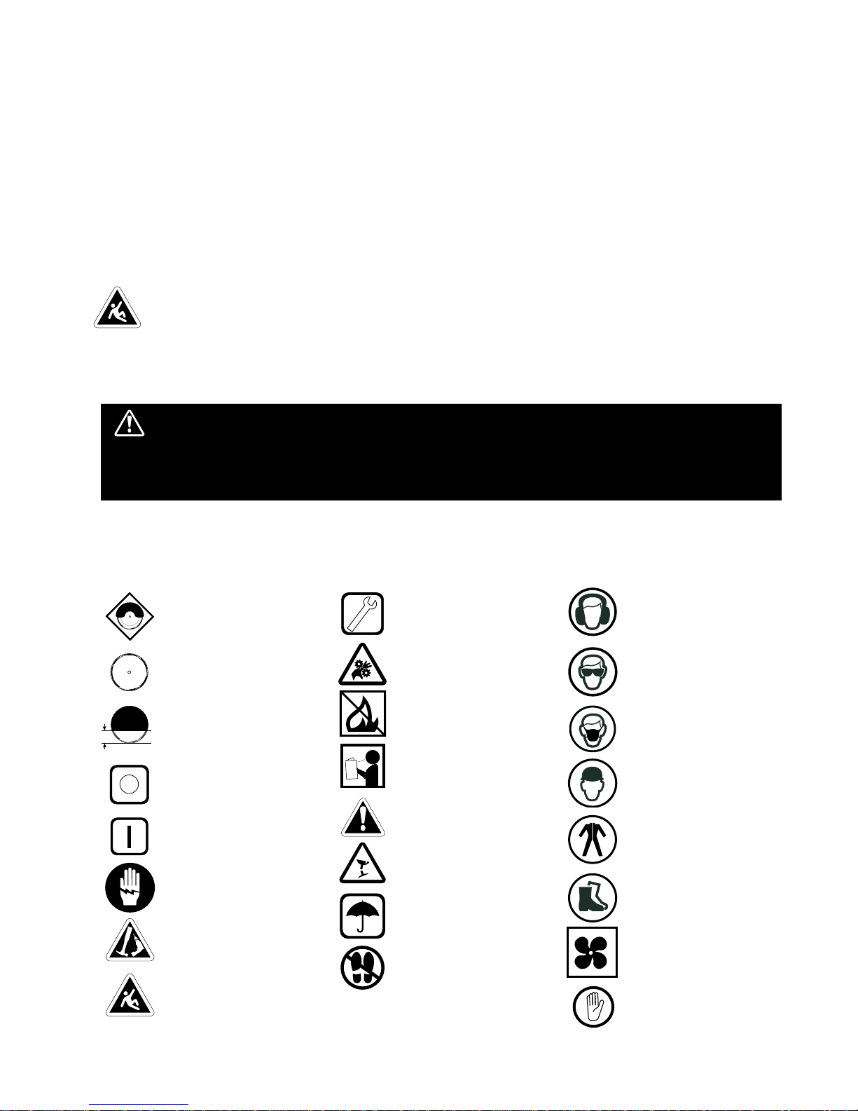
KEEP GUARD IN
PLACE
DIAMOND BLADE
BLADE CUTTING
DEPTH
ELECTRIC SWITCH OFF
ELECTRIC SWITCH ON
ELECTRICAL HAZARD
REMOVE TOOLS
PAY EXTREME
ATTENTION
ii. SYMBOLS
REPAIRS TO BE DONE
MACHINE HAZARD
FLAMMABLE
READ INSTRUCTIONS
CAREFULLY
WARNING
FRAGILE
KEEP DRY
DO NO STEP ON
WEAR HEARING
PROTECTION
WEAR EYE PROTECTION
WEAR BREATHING
PROTECTION
WEAR HARD HAT
WEAR PROTECTIVE
CLOTHING
WEAR SAFETY SHOES
WELL VENTILATED
NO NON-WORKING
PERSONNEL
Page 6
iii. FEATURES
The TYROLIT TTE250 is a portable professional tile saw. Lightweight and compact it has innovative built
in features that enable it to cut larger format tiles. The unique coaction movement of the cutting head and
main table allow the saw to increase its cutting capacity whenever needed. The main table and extension
carriage are supported by low friction, self cleaning, adjustable guide wheels. Water flow to the blade is
provided by two (2) nozzles that direct the water to both sides of the blade. The rugged powder coated
metal and aluminum frame sets in a removable water tray for easy clean up.
• Powerful Motor - 1.1 kW.
• Circuit breaker protects your saw from power surges and overheating.
• High Impact ABS Water Tray.
• Adjustable Cutting Head allows user to align saw at any time.
• Cutting alignment not affected by water tray maintenance.
• Blade Capacity 250mm.
• Diagonal cut up to 460mm tiles and rip cut up to 730mm in length.
The heavy duty, cast to last construction and quality components were designed to meet the highest
demands of the professional.
Read this manual completely and then let the TYROLIT TTE250 take your cutting capabilities to new
dimensions.
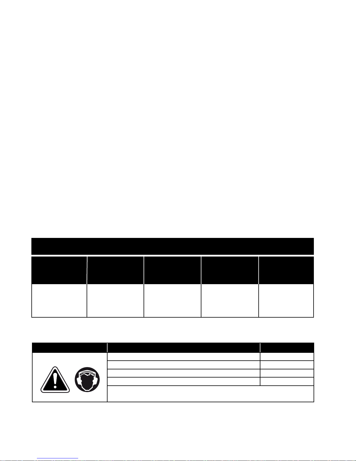
iv. SPECIFICATIONS
TYROLIT TTE250 TILE SAW
MOTOR
1.1kW
110 V, 50 Hz or
ARBOR SHAFT
ROTATION
Counter-
Clockwise
230V, 50 Hz
Single phase*
* The motor is designed to operate on either 110V or 230V mains, but not both. Refer to the name plate located behind
the motor for power requirements specific to your motor.
Noise level at the ear of the user (Leq) 93.7 dB(A)*
Noise level at workplace (LPA) 80.5 dB(A)*
Sound power level in accordance with ISO 3744 (LwA) 100.5 dB(A)*
Vibrations DIN EN ISO 5349-2 < 2.5 m/s²
*Value applies under the following condition: With Sawblade Ø250mm Type EB No. 5504014.
Higher noise levels may be generated in cutting operation.
MAX. BLADE
CAPACITY
WEIGHT
25.4mm arbor blade,
250mm Blade
Noise level and vibrations
DIMENSIONS
26 kg Width: 600mm
Length: 900mm
Hight: 500mm
ATTENTION! Hearing protection must be worn when 90 dB(A) is exceeded!
– 5 – – 6 –
Page 7
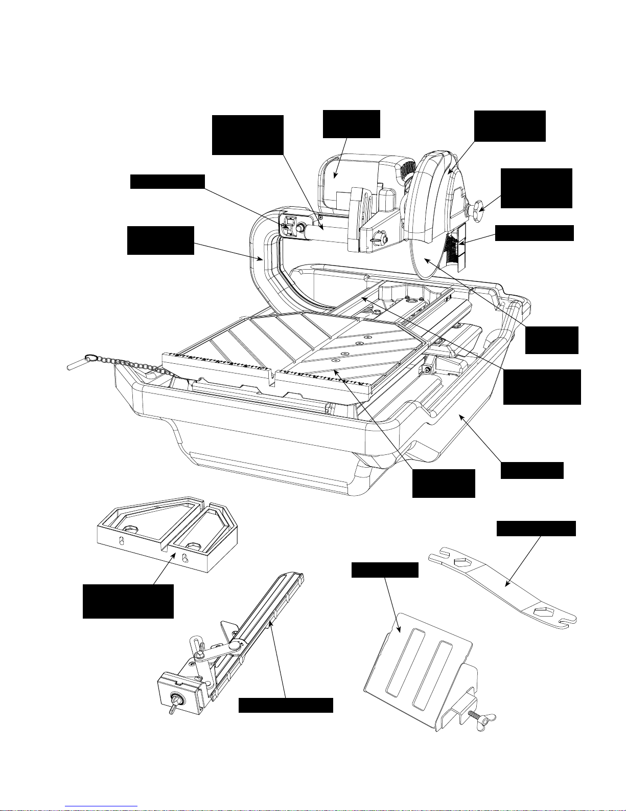
v. GETTING TO KNOW YOUR SAW
Power Switch
Vertical Arm
Assembly
Cutting Head
Adjustment
Handle
Motor
Assembly
Blade Guard
Assembly
Blade Guard
Adjustment
Knob
Splash Guard
Diamond
Blade
Rail Platform
Assembly
Side Extension
Table
MasterGuide
Miter Block
Main Table
Assembly
Water Tray
Blade Wrench
Page 8
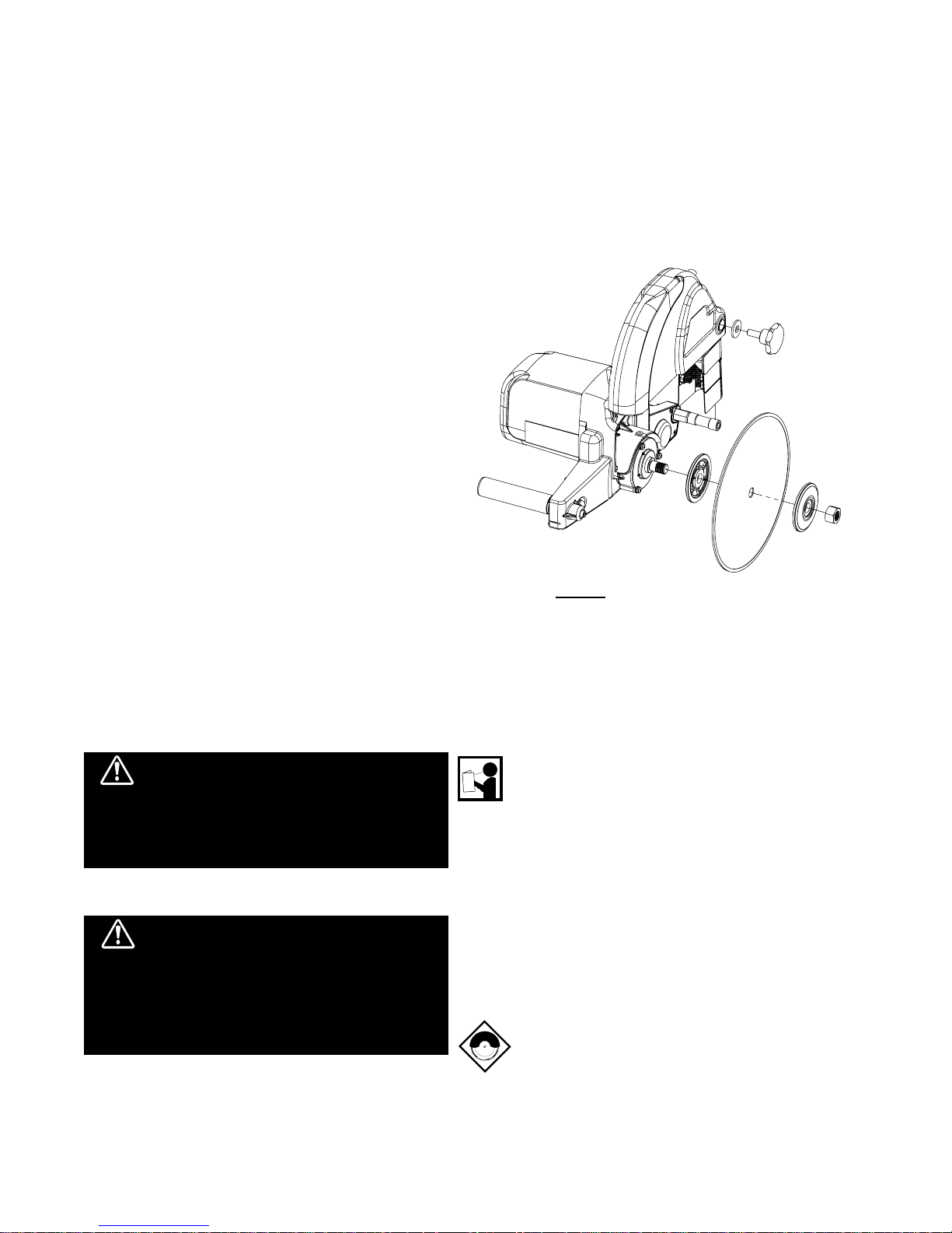
vi. BLADE INSTALLATION
1. Carefully raise the cutting head to its highest
position and secure it into place by tightening the
cutting head adjustment knob located in the front
of the saw, to the right of the power switch.
2. Raise the blade guard to the highest position and
tighten the blade guard adjustment knob.
3. Remove the blade shaft nut and outer flange.
4. Place the blade onto the shaft making sure that the
directional arrows are pointing in the direction of
rotation.
5. After making sure that the blade is firmly placed
against the inner flange, secure it into place with
the outer flange and blade shaft nut. Make certain
the nut is firmly tightened with the wrench provided,
do not over tighten!
but
7. Lower the blade guard and tighten the adjustment
knob.
8. Slightly loosen the cutting head adjustment knob
and lower the cutting head to its lowest position,
and then tighten the adjustment knob firmly to hold
the cutting head in place.
WARNING: Setting the blade too high may cause
the blade to grap the material being cut, causing
damage and possibly injury.
Figure 1
vii. SAFE OPERATING PRACTICES FOR TILE SAW
WARNING!
For your own safety and the safety
of others do not attempt to operate this saw until you
have read and understand the general safety rules
for all power tools and the following additional safety
precaution unique to this saw.
1. Use safety equipment - wear safety approved
hearing, eye, head and respirator protection.
WARNING!
The dust generated by cutting of
tile, marble, stone, bricks etc. can be injurious to your
health. Always operate machinery in well ventilated
areas and provide proper dust removal. Always wear a
dust mask approved for respiratory protection against
these types of dusts and mists.
2. Read and understand the symbol definitions
contained in this manual.
3. Read and understand all warnings and instructions
on the machine.
4. Read all safety materials and instructions that
accompany any blade or accessory used with this
machine.
5. Establish a training program for all operations of
this machine.
6. Always provide a copy of this manual to the
equipment user. If you need extra copies call our
Customer Service Department.
7. Always select a diamond blade according to the
manufacturers recommendation suitable for the
material to be cut. Never use a blade having a
maximum operating speed lower than the “No load
R.P.M.” marked on the tool nameplate. Do not
operate any saw without safety guards in place
or with a blade diameter larger than the maximum
– 7 – – 8 –
Page 9

saw blade capacity.
8. Before mounting a blade on the saw clean and
inspect the arbor shaft, blade flanges and the
diamond blade for uneven wear or damage. If it
appears to be damaged, Do not operate the tool.
Have it serviced by a qualified service technician.
9. Before each use of the saw, inspect the diamond
blade for hairline fatigue cracks. If such a crack
or flaw is evident, discard the blade. Using a
damaged blade may cause injury to the operator
or others.
14. Before using the saw fill the water tub enough to
submerge the water pump with clean water only.
Replenish as necessary and clean the water tub
frequently. Do not operate a wet cutting blade
without adequate water flow to both sides of the
blade. Never run the pump dry.
15. When cutting, always hold the material firmly lying
flat, supported by the main table with one edge
resting against the main table backstop.
• Do not attempt to cut pieces too small to
safely hold down on the main table.
10. Be sure that the blade arbor hole matches the
blade adapter flange supplied with the saw. Use
only blade adapter flanges that came on your
saw. Never use damaged or worn blade adapter
flanges.
11. Installing the blade, install the blade with the
arrow pointing the same direction as the rotation
of the arbor shaft or the arrow on the blade guard.
Be sure to tighten the blade shaft arbor nut with the
wrench provided. Be careful not to over tighten.
WARNING!
Not dressing the blade frequently or
setting the blade too high will cause it to grab the tile
possibly causing injury to the operator and the saw.
12. Check that the blade tracks near the center of the
channel in the main table, and that the table moves
freely from front to back.
13. Sometimes the material being cut is not abrasive
enough to expose new diamonds on the blade.
If the blade is not sharpened, it will rub against
the surface resulting in heat build up in the core.
To prevent this, it is necessary to dress the
blade. To dress the blade simply cut something
that is very abrasive such as a piece of cement
block. Indications that the blade needs dressing
includes:
• The diamond in the matrix appear shiny
because they are worn flat.
• Never use the side of the blade to cut or grind
with, only cut in a straight line.
• Keep all parts of your body away from the
blade and all other moving parts.
• Never touch or try to stop a moving blade with
your hand.
16. When cutting dry - always unplug the water pump
first. Never run the pump dry.
• Do not use a wet cutting blade for dry cutting.
Select the proper dry cutting blade for your
application.
• Never make long continuous cuts with dry
cutting blades. To avoid heat build up, allow
the blade to cool, remove the tile and allow
the blade to run freely for a few minutes.
IMPORTANT - If there is any tendency for the
saw to move during certain operations, such as
when cutting large heavy tile; the saw must be
securely fastened to a supporting table.
17. Make certain all adjusting knobs or locks are tight
and engaged in their detents and that movable
parts not intended to move during operation are
securely locked before making a cut.
Be careful
not to over tighten.
18. Before connecting the machine to a power source
check to see that the “On/Off” switch is in the “off”
position.
• The blade stops cutting or noticeably slows
down.
Blade dressing stones are available from your local TYROLIT
distributor.
• Make sure the blade is not contacting anything
before connecting to a power source and
starting the motor.
• Know how to stop the machine quickly in case
of an emergency.
Page 10

(A) (B) (C)
Cover of grounded
outlet box
Grounding pin
Grounding
Means
(Lug)
Metal
Screw
(D)
(E)
Grounding pin
Figure 2
Grounding Methods
19. Grounding Instructions
• In the event of a malfunction or breakdown,
grounding provides a path of least resistance
for electric current to reduce the risk of
electric shock. This tool is equipped with an
electric cord having an equipment-grounding
conductor and a grounding plug. The plug
must be plugged into a matching outlet that is
properly installed and grounded in accordance
with all local codes and ordinances.
• Do not modify the plug provided - if it will not
fit the outlet, have the proper outlet installed
by a qualified electrician.
• Improper connection of the equipment
grounding conductor can result in a risk of
electric shock.
• Check with a qualified electrician or service
personnel if the grounding instructions are
not completely understood, or if in doubt as to
whether the tool is properly grounded.
• Use only 3 wire extension cords that have 3
prong grounding plugs and 3 pole receptacles
that accept the tool’s plug.
Repair or replace damaged or worn cord immediately.
This tool is intended for use on a circuit that has an outlet
that looks like the one illustrated in
Figure 2. The tool has a
grounding plug that looks like the plug illustrated in Figure
2(A). A temporary adapter, which looks like the adapter
illustrated in Figure 2(B) and 2(C), may be used to connect
this plug to a 2 pole receptacle as shown in Figure 2(B) if
a properly grounded outlet is not available. The temporary
adapter should be used only until a properly grounded outlet
can be installed by a qualified electrician. The green-colored
rigid ear, lug, and the like, extending from the adapter must be
connected to permanent ground such as a properly grounded
outlet box.
NOTE - Use of a Temporary Adapter is not permitted
in certain countries. Please check local regulations
before using a Temporary Adapter.
Additionally, water pump requires the use of a Ground Fault
Circuit Interrupter. Therefore, when using the water pump
receptacle, this tool must be plugged into a properly installed
Ground Fault Circuit Interrupter outlet. See Figure 2(D). If
a Ground Fault Circuit Interrupter outlet is not available,
TYROLIT Hydrostress AG has it available as an accessory
item. A plug-in Ground Fault Circuit Interrupter may be
plugged into a properly installed and grounded 3-pole outlet.
Refer to
Figure 2(E).
20. Position of the Tile Saw
• To avoid the possiblity of the appliance plug or
receptacle getting wet, position tile saw to one
side of a wall mounted receptacle to prevent
water from dripping onto the receptacle or
plug. The user should arrange a "drip loop" in
the cord connecting the saw to a receptacle.
The "drip loop" is that part of the cord below
the level of the receptacle, or the connector if
an extension cord is used, to prevent water
traveling along the cord and coming in contact
with the receptacle.
See Figure 3.
• If the plug or receptacle does get wet, Do
not unplug the cord
. Disconnect the fuse or
circuit breaker that supplies power to the tool.
Then unplug and examine for presence of
water in the receptacle.
To reduce the risk of electrocution, keep
all connections dry and off the ground.
Do not touch plug with wet hands.
– 9 – – 10 –
Page 11

21. Extension Cords
TOOL
• Use only extension cords that are intended
for outdoor use. These extension cords are
indentified by a marking
"Acceptable for use
with outdoor appliances; store indoors while
not in use." Use only extension cords having
an electrical rating not less than the rating of
the product.
Refer to chart on page 21. Do
no use damaged extension cords. Examine
extension cord before using and replace if
damaged. Do no abuse extension cords
and do not pull on any cord to disconnect.
Keep cord away from heat and sharp edges.
Always disconnect the extension cord
from the receptacle before disconnecting
the saw from the extension cord.
• Ground Fault Circuit Interrupter (GFCI)
protection should be provided on the circuit(s)
or outlet(s) to be used for the tile saw.
Receptacles are available having built-in
GFCI protection and may be used for this
measure of safety.
Supporting
Surface
Power Cord
Figure 3
Drip Loop
Drip Loop
Features:
• Cutting table marked in inches for precision cuts.
• 350mm cutting table provides more support during
larger cutting jobs than the standard 280mm
cutting tables.
Using MasterGuide:
1. Set the MasterGuide by positioning it at the desired
dimension on the measurement rail and firmly
tighten the horizontal threaded knob. When using
the attached ruler, the guide can be used to make
cuts betwen 45º and 90º. To adjust the cutting
angle first loosen the vertical threaded knob.
2. The guide can also be used without the ruler
attachment to make 90º cuts on either the left
or right edge. The guide contains multiple 45º
templates to allow diagonal cuts of common tile
sizes. Position the guide for a diagonal cut by
aligning the desired template along a diagonal
groove on the table. To remove the ruler first
remove the vertical threaded knob.
3. After positioning the guide, place the material flat
against the guide and the table measurement rail.
Now you are ready to make your cut.
viii. USING THE CUTTING TABLE
Making Miter Cuts (Using Miter Block):
1. For miter cuts, place the lip of the miter block on
the measurement rail, with the threaded knobs
facing you.
2. Tighten the threaded knobs to secure the miter
block in place.
3. Place material onto miter block and you are ready
to cut.
Figure 4
Cutting large tile
TTE250 can cut a 610mm tile and
diagonally cut a 460mm tile.
TTE250 shown with optional drip trays.
Page 12

xix. CARE AND MAINTENANCE
WARNING!
For your safety before performing any maintenance on the saw turn off the power switch and unplug
the power cord.
TYROLIT TTE250 requires very little maintenance.
However, keeping your saw clean and properly adjusted will
ensure optimum performance. Take great care not to get
water into the motor. Do no use pressure washer to clean
motor area.
1. Cleaning
• Form a habit of cleaning your saw after each
use. To clean the water tub, remove drain
plug provided in bottom of tub. Remove
saw including water pump from tub. Remove
residual water and clean tub using soap and
water only. Reinstall saw with pump into tub.
• To increase water pump life remove tile grit
by purging water. Pump with fresh water after
each use.
• With a damp cloth or sponge wipe clean the
guide rails and all other surfaces on the saw
where dust and debris has accumulated.
NOTE - Do not lubricate the guide rails. The presence
of oil or grease will cause an accumulation of dust
and dirt.
2. Transporting
• Unplug the power cord and store it in the
empty, dry water tub. For convenience and
safety, the saw should be transported with the
main table
locked, motor in upper position
and all adjustment knobs tightened.
3. Sliding Vertical Arm Assembly Adjustment
C. Tighten nyloc nut when finished to secure
rollers in place. Be sure not to overtighten.
Set screw to adjust
roller tension
Nyloc nut is found
under the base
Assembly Roller Adjustment
Figure 5
4. Table Roller Adjustment
A. Loosen (4) hex screws on table top.
B. Adjust tension on rollers by turning set screw
(on outside of table) until desired tension is
achieved.
DO NOT OVERTIGHTEN. See
Figure 6.
C. Re-tighten the (4) hex screws on table top.
Check table movement and re-adjust if
necessary. Table should roll free but without
side movement.
Figure 6
Table Roller Adjustment
Adjust table tension
through this set screw
• Make sure that all rails and rollers are clean.
• If the vertical arm assembly does not slide
smoothly, it will require tension adjustment as
follows:
A. Locate the two tension rollers mounted onthe
black base of the vertical arm assembly
furthest from the arm. Use a wrench to loosen
the nyloc nut directly below each roller. Use
another wrench to prevent the bolt on top from
turning.
See Figure 5.
B. Use the horizontal set screw to adjust roller
tension against the rails. The rollers should
roll free but without side movement.
NOTE - Whenever making tension adjustments to
rollers on the vertical arm assembly or table, the
stainless steel wire linking the two components
together should be disconnected first. Otherwise, it
will not be possible to determine which rollers will
require adjustment. See Section 5 for steps.
– 11 – – 12 –
Page 13

5. Unlinking Coaction Wire
A. Remove the wire shield located between the
rails by removing the screws at both ends.
B. Loosen the nyloc nuts on the wire anchor
underneath the table so that the wire can pass
freely through the bolt. Be sure to use an
allen key to prevent the bolt from turning.
Failure to do so may cause the wire to
break. See Figure 7.
Loosen both nyloc nuts
C. Perform the necessary adjustments. Proceed
to next step once completed.
D. Move the table towards the user, such that
the forward-most roller touches the rubber
stopper at the end of the rail. Then move the
vertical arm assembly to the opposite end,
while leaving a small gap between the rearmost roller and frame.
E. Tighten the nyloc nuts on the wire anchor,
while preventing the bolts from turning.
F. Replace the wire shield.
6. Aligning the Blade to the Table
• While cutting, the material being cut must
move in a straight line parallel to the saw
blade. If the blade is out of plane it will bind
at one end of the cut. To align the blade,
perform the following:
Figure 7
Unlinking the Table
Insert allen key to
prevent bolt from turning
Pivot adjuster
C. Tighten lower socket hex bolt when finished.
D. Check alignment by placing an L-shaped
L-shaped
straight edge
Resistance encountered while turning the
pivot adjuster indicates that rollers are being
forced against the rail. Lower roller tension
before proceeding.
Figure 8
Blade Alignment
Loosen socket hex bolt
With the pivot adjuster secured, adjust the
remaining rollers to obtain proper tension
against the rails.
See Section 3.
straight edge on the table with the short arm
resting flat against the table back stop. The
long arm should rest against the blade with
the cutting head completely lowered. Check
to see if there are any gaps between the
leading or trailing edges of the blade and
the straight edge. If gaps exist, then repeats
steps A - C until alignment is attained.
See
Figure 9.
Figure 9
Table Roller Adjustment
Blade
A. Locate the pivot adjuster on the black base
of the vertical arm assembly next to the arm.
Loosen the socket hex bolt directly below the
adjuster.
See Figure 8.
B. Turn pivot adjuster using a wrench either
clockwise (putting the roller into the rail) or
counterclockwise (pulling the roller away from
the rail). While the pivot adjuster determines
blade alignment, the rollers on the opposite
side of the assembly base
must also be adjusted simultaneously so
that they run parallel to the rollers closest to
the vertical arm. Do not apply excessive
force when turning the pivot adjuster.
(see Section 3)
Table back stop
7. Positioning the Saw in the Tub
A. Orient the saw such that the front is pointing
towards the short side of the tub with the
beveled corner.
B. While lowering the saw into the tub, ensure
that brackets at both ends of the saw frame
Page 14

fit over the recessed portions of the tub wall.
See Figure 10.
Figure 10
Positioning the Saw
E. Remove the water pump underneath the rails
and install a new one in its place. Remove the
water tube and adapter from the failed pump.
F. Insert power cable from the new pump through
the cable gland and shield sleeve and route it
up the vertical arm. The gland must be
oriented such that it can attach to the sleeve.
G. Connect wiring from the water pump power
cable to the same wires made available when
disconnecting the failed pump.
Recessed wall
8. Tub & Tray
A. Insert the large rubber stopper in the drain
Figure 11
.
9. Replacing the Water Pump
• In the event of a water pump failure, replace
Bracket
See Figure 11.
hole.
Rubber stopper
the pump by performing the following steps:
H. Install shield onto vertical arm using screws.
I. Gently extract excess cable stored within
vertical arm; some slack is ideal. Tugging the
cable may dislodge or disconnect critical
electrical components. Attach cable gland
onto the shield sleeve by turning clockwise.
If properly attached, the gland should secure
the cable in place.
J. Attach the adapter to the pump and hand
tighten. Do not use a wrench as it can strip
the thread.
K. Connect clear tubing to male section of the
adapter until it fits securely.
Figure 14
Water tubing
See Figure 14.
Adapter
A. Remove the cable gland located at the bottom
of the vertical arm shield by turning it counterclockwise. Once removed, the cable should
slide freely within the underlying sleeve.
Figure 13.
B. Remove screws from the vertical arm shield,
then remove the shield.
C. Disconnect wiring from the water pump power
cable within the vertical arm.
D. Extract the power cable from the vertical arm
through the sleeve at the bottom of the shield.
Keep the cable gland.
See
Figure 13
Remove Cable Gland
– 13 – – 14 –
Page 15

x. CUTTING DEPTH
The recommended cutting depth is 6mm below the cutting
table surface. To adjust the cutting depth, loosen the cutting
head adjustment handle and set it to the lowest position, so
that the blade is 6mm below the top of the table surface.
WARNING: Setting the blade too high may
cause the blade to grab the material being cut,
possibly causing injury to the operator and the
saw.
xi. REPLACEMENT PARTS LIST
MAIN ASSEMBLY
82018 17 10 9
11
3
BLADE DIAMETER CUTTING DEPTH
250mm 60mm
5 14 15
16
13
6 19
4
7
12
2
Pos Art. No. Description
1 10985786 EOSM-420150 RAIL PLATFORM ASSEMBLY
2 10985678 EOSM-420002 TABLE ASSEMBLY
3 10985787 EOSM-420151 VERTICAL ARM (110V/50HZ)
10985788 EOSM-420152 VERTICAL ARM (230V/50HZ)
4 10985789 EOSM-420153 CUTTING HEAD (110V/50HZ)
10985790 EOSM-420154 CUTTING HEAD (230V/50HZ)
5 10985791 EOSM-420155 BLADE GUARD ASSEMBLY
6 10985679 EOSM-420006 DIA 5/8” OUTER FLANGE
7 250mm Cont. general purpose blade
8 10985680 EOSM-420007 D30 X 120L HANDLE
9 10985681 EOSM-420008 SPRING
10 10985682 EOSM-420009 SLIP COLLAR
11 10985683 EOSM-420010 INTERLOCK WASHER
12 10985792 EOSM-420156 WATER PUMP (110V/50HZ)
10985793 EOSM-420157 WATER PUMP (230V/50HZ)
13 10985684 EOSM-420012 M6X1.0X25L HEAD HEX BOLT
1
Pos Art. No. Description
14 10985685 EOSM-420013 M10 NARROW WASHER
15 10985686 EOSM-420014 MALE M10 X 1.5 X 25L KNOB
16 10985687 EOSM-420015 M8 X 1.25 ACORN NUT
17 10985688 EOSM-420016 M8 NARROW WASHER
18 10985689 EOSM-420017 M8X1.25X35L CROSS SCREW
19 10985912 EOSM-PSV00004 5/8” - 11 HEX NUT
20 10985806 EOSM-420170 DIA 1” INNER FLANGE
20 10987292 EOSM-420305 DIA 1” INNER FLANGE 1/ -1.5
20 10987293 EOSM-420306 DIA 1” INNER FLANGE 2/ -1
20 10987294 EOSM-420307 DIA 1” INNER FLANGE 3/ -0.5
20 10985806 EOSM-420305 DIA 1” INNER FLANGE 4/ 0
20 10987295 EOSM-420308 DIA 1” INNER FLANGE 5/ 0.5
20 10987296 EOSM-420309 DIA 1” INNER FLANGE 6/ 1
20 10987297 EOSM-420310 DIA 1” INNER FLANGE 7/ 1.5
Page 16

CUTTING HEAD ASSEMBLY
8
910
32
25
26
11 24
28 29
3
12
13
17
181920
7
16
15
4
5 31 1430 22
Pos Art. No. Description
1 10985690 EOSM-420027 CUTTING HEAD
2 10985691 EOSM-420028 GEAR CAP
3 10985692 EOSM-420029 BLADE GUARD SHAFT
4 10985693 EOSM-420030 BLADE SHAFT
5 10985694 EOSM-420031 HELICAL GEAR
6 10985794 EOSM-420158 BRUSH MOTOR (110V/50HZ)
10985795 EOSM-420159 BRUSH MOTOR (230V/50HZ)
7 10985695 EOSM-420033 FAN COVER
8 10985696 EOSM-420034 SPRING TENSION PLATE
9 10985697 EOSM-420035 TORSIONAL SPRING
10 10985698 EOSM-420036 SPRING SPACER
11 10985699 EOSM-420037 SPRING HOUSING COVER
12 10985700 EOSM-420038 17MM X 7MM CARBON BRUSH
10985796 EOSM-420160 CARBON BRUSH (230V/50HZ)
13 10985701 EOSM-420039 CARBON BRUSH CAP
14 10985702 EOSM-420040 D40 D24 OIL SEAL
15 10985703 EOSM-420041 M5 NARROW WASHER
21 2 152716 23
6 1
Pos Art. No. Description
16 10985704 EOSM-420042 M5 SPRING WASHER
17 10985705 EOSM-420043 M5X0.8X25L CROSS SCREW
18 10985706 EOSM-420044 M4 NARROW WASHER
19 10985707 EOSM-420045 M4 SPRING WASHER
20 10985708 EOSM-420046 M4X0.7X20L CROSS SCREW
21 10985709 EOSM-420047 5MM X 16MM WOODRUFF KEY
22 10985710 EOSM-420048 M20 EXTERNAL C-CLIP
23 10985711 EOSM-420049 M5X0.8X15L CROSS SCREW
24 10985712 EOSM-420050 M4X0.7X10L CROSS SCREW
25 10985713 EOSM-420051 M8 SPRING WASHER
26 10985714 EOSM-420052 M8 X 1.25 X 20L HEX BOLT
27 10985715 EOSM-420053 M10 X 1.5 NUT
28 10985685 EOSM-420013 M10 NARROW WASHER
29 10985716 EOSM-420054 D6 CIRCULAR RUBBER STOP
30 10985717 EOSM-420055 D22 D8 608 RADIAL BEARING
31 10985718 EOSM-420056 D47 D20 RADIAL BEARING
32 10985719 EOSM-420057 M8 REGULAR WASHER
– 15 – – 16 –
Page 17

VERTICAL ARM ASSEMBLY
29
32 36 33 34
110V/50Hz
5
28
11
22
10
6
17
16
15
30
18
44
45
230V/50Hz
1 21
13
14
42
43
3
2
30
4
27
26
1
23
35
7
46
24
37
39
38
19
8
31 92514
Pos Art. No. Description
1 10985797 EOSM-420161 POST
2 10985798 EOSM-420162 POST ELECTR. ACCESS PLATE
3 10985720 EOSM-420060 RUBBER GASKET
4 10985799 EOSM-420163 PLATE
5 10985721 EOSM-420062 CUTTING HEAD BRACKET
6 10985800 EOSM-420164 POST BASE
7 10985722 EOSM-420064 ROLLER ADJUSTMENT MOUNT
8 10985723 EOSM-420065 ROLLER MOUNT
9 10985714 EOSM-420052 M8 X 1.25 X 20L HEX BOLT
10 10985724 EOSM-420066 WIRE ANCHOR BRACKET
11 10985725 EOSM-420067 M6 X 1.0 X 15L HEX BOLT
12 10985726 EOSM-420068 M8 X 1.25 X 45L HEX BOLT
13 10985704 EOSM-420042 M5 SPRING WASHER
14 10985711 EOSM-420049 M5X0.8X15L CROSS SCREW
15 10985727 EOSM-420069 1/4”-20X1/2” FLAT SCREW
16 10985728 EOSM-420070 1/4” - 20 NUT
17 10985729 EOSM-420071 M6 NARROW WASHER
18 10985730 EOSM-420072 M8 X 1.25 X 35L HEX BOLT
19 10985731 EOSM-420073 LOWER ROLLER SPACER
20 10985732 EOSM-420074 1/4” NARROW WASHER
21 10985703 EOSM-420041 M5 NARROW WASHER
22 10985733 EOSM-420075 WIRE TENSION BOLT
23 10985734 EOSM-420076 1/4”-20X2”X3/4” CAP BOLT
20 40
1241
Pos Art. No. Description
24 10985735 EOSM-420077 1/4”-20X1-1/4”X3/4” BOLT
25 10985736 EOSM-420078 1/4” - 20 NYLON NUT
26 10985737 EOSM-420079 M8 X 1.25 NYLON NUT
27 10985738 EOSM-420080 DIA 8MM CABLE GLAND
28 10985739 EOSM-420081 M8X1.25X20L CROSS SCREW
29 10985740 EOSM-420082 M5X0.8X16L CROSS SCREW
30 10985741 EOSM-420083 M4X0.7X13L CROSS SCREW
31 10985742 EOSM-420084 M6 SPRING WASHER
32 10985743 EOSM-420085 20A 125V/12A 250V SWITCH
33 10985744 EOSM-420086 15A CIRCUIT BREAKER
34 10985745 EOSM-420087 POWER SWITCH GASKET
35 10985746 EOSM-420088 M6 X 1.0 NYLON NUT
36 10985747 EOSM-420130 POWER SWITCH PLATE
37 10985916 EOSM-V31005-MA WATER SHIELD
38 10985915 EOSM-V31004-MA BYPASS SPACER
39 10985748 EOSM-420090 TYPE 5 GUIDE ROLLER
40 10985713 EOSM-420051 M8 SPRING WASHER
41 10985688 EOSM-420016 M8 NARROW WASHER
42 10985706 EOSM-420044 M4 NARROW WASHER
43 10985749 EOSM-420091 M4 X 0.7 X 8L CROSS SCREW
44 10985801 EOSM-420165 12A 220V-250V EL. SWITCH
45 10985802 EOSM-420166 POWER SWITCH PLATE
46 10985803 EOSM-420167 DIA 7MM CABLE GLAND
Page 18

TABLE ASSEMBLY
18 17 7 2
6 13 5
19
15
16
Pos Art. No. Description
1 10985750 EOSM-420092 MAIN TABLE
2 10985751 EOSM-420093 WIRE ANCHOR PLATE
3 10985917 EOSM-V31014-MA ROLLER MOUNTING PLATE
4 10985918 EOSM-V31015-MA NUT PLATE, TABLE
5 10985752 EOSM-420094 WIRE BOLT ANCHOR
6 10985746 EOSM-420088 M6 X 1.0 NYLON NUT
7 10985729 EOSM-420071 M6 NARROW WASHER
8 10985753 EOSM-420095 UPPER ROLLER SPACER
9 10985916 EOSM-V31005-MA WATER SHIELD
10 10985915 EOSM-V31004-MA BYPASS SPACER
11 10985754 EOSM-420096 ROLLER
12 10985731 EOSM-420073 LOWER ROLLER SPACER
13 10985755 EOSM-420097 M6 WIDE WASHER
14 10985756 EOSM-420098 1/4”-20X1-1/4”X3/4” BOLT
15 10985924 EOSM-V3816 1/4”-20X1-1/4” HEAD SCREW
16 10985728 EOSM-420070 1/4” - 20 NUT
17 10985742 EOSM-420084 M6 SPRING WASHER
18 10985757 EOSM-420099 M6 X 1.0 X 14L HEX BOLT
19 10985923 EOSM-V3815 1/4”-20X1.5”L HEX BOLT
BLADE GUARD ASSEMBLY
12
11
10
14
1
3
8
4
9
9
1 6 7 10 5
Pos Art. No. Description Description
1 10985804 EOSM-420168 TYROLIT 250MM BLADE GUARD
2 10985758 EOSM-420101 SPLASH GUARD
3 10985729 EOSM-420071 M6 NARROW WASHER
4 10985759 EOSM-420102 M6 X 1.0 X 10L HEX BOLT
5 10985708 EOSM-420046 M4X0.7X20L CROSS SCREW
6 10985760 EOSM-420103 12CM PIPE
7 10985761 EOSM-420104 120CM PIPE
8 10985762 EOSM-420105 39CM PIPE
9 10985763 EOSM-420106 D8MM Y-SHAPE CONNECTORS
10 10985706 EOSM-420044 M4 NARROW WASHER
9
8
3
4
2
– 17 – – 18 –
Page 19

RAIL PLATFORM ASSEMBLY
21
11
21
20
19
2
7
8
10
12
5
1
9
4
26
23
24
14
15
6
21
13
3
25
24
23
18
17
22
5
25
24
23
23
24
25
Pos Art. No. Description
1 10985805 EOSM-420169 RAIL PLATFORM
2 10985764 EOSM-420108 PULLEY MOUNT AND CAP
3 10985765 EOSM-420109 FRONT PLATFORM ANCHOR
4 10985766 EOSM-420110 REAR PLATFORM ANCHOR
5 10985767 EOSM-420111 RAIL
6 10985768 EOSM-420112 SKID PLATE
7 10985769 EOSM-420113 SHAFT SPACER
8 10985770 EOSM-420114 SHAFT
9 10985771 EOSM-420115 RUBBER BUMPER
10 10985772 EOSM-420116 WIRE PULLEY ASSEMBLY
11 10985773 EOSM-420117 WIRE SHIELD
12 10985774 EOSM-420118 D2 STAINLESS STEEL WIRE
13 10985775 EOSM-420119 SCREW DRIVEN WIRE CLAMP
Pos Art. No. Description
14 10985776 EOSM-420120 RUBBER FEET
15 10985777 EOSM-420121 M5X0.8X10L CROSS SCREW
16 10985778 EOSM-420122 CHAIN
17 10985779 EOSM-420123 D21 RING
18 10985780 EOSM-420124 D8 X 45L QUICKRELEASE PIN
19 10985706 EOSM-420044 M4 NARROW WASHER
20 10985707 EOSM-420045 M4 SPRING WASHER
21 10985781 EOSM-420125 M4X0.7X10L CROSS SCREW
22 10985922 EOSM-V3808 1/4”-20X5/8”L HEX BOLT
23 10985703 EOSM-420041 M5 NARROW WASHER
24 10985704 EOSM-420042 M5 SPRING WASHER
25 10985777 EOSM-420121 M5X0.8X10L CROSS SCREW
26 10985782 EOSM-420126 M4 X 0.7 NUT
Page 20

xii. ACCESSORIES
Name (Qty.)
ABS WATER TRAY (1)
Art. No.
10985783
Part Number
420127
EOSM-
Name (Qty.)
JOLLY-TISCH (1)
Art. No.
10978736
Part Number
S700-34
EOSM-
Name (Qty.)
MASTERGUIDE (1)
Art. No.
10980453
Part Number
EOSM-S1000-MG
Name (Qty.)
SIDE EXTENSION
TABLE (1)
Art. No.
10985921
Part Number
EOSM-V38008
Optional
Name (Qty.)
KNOB RIP GUIDEMITER
BLOCK (1)
Art. No.
10985920
Part Number
EOSM-V35016
Name (Qty.)
ABLAUFSTOPFEN (1)
Art. No.
10980464
Part Number
EOSM-V35015
Optional
Name (Qty.)
SÄGETISCH FALTBAR (1)
Art. No.
10984479
Part Number
EOSM-CX10ST
– 19 – – 20 –
Page 21

xiii. HOW TO ORDER PARTS
Type TTE250 Article No. 10983906
Serial No. Index 001250070001
Power 1,1 kW Voltage 230V/50Hz
Weight 26 kg Year 2007
Please have the following information ready before ordering spare parts:
• Machine type according to nameplate (e.g. TTE250)
• Machine serial number according to nameplate (e.g. 250070001)
• Machine index according to nameplate (e.g. 001)
• Spare part number according to the spare parts list (e.g. 12345678)
To avoid incorrect deliveries you should check the order details above for correctness and completeness prior to shipment. You should
ensure that the delivery address is given in full.
For orders, questions and information please contact your responsible branch office below:
TYROLIT Hydrostress AG
Witzbergstrasse 18
CH-8330 Pfäffikon
Switzerland
Tel. 0041 (0)44 952 18 18
Fax 0041 (0)44 952 18 00
www.tyrolit.com
Disclaimer: TYROLIT Hydrostress AG reserves the right to make changes or improvements on its products without incurring an
additional obligation including any obligation to make corresponding changes or improvements to products previously manufactured
or sold. TYROLIT reserves the right to discontinue products at any time without notice.
All illustrations displayed in this manual are the property of TYROLIT Hydrostress AG and shall not be duplicated or reproduced without
the express written consent of TYROLIT Hydrostress AG.
Page 22

xiv. ELECTRICAL MOTOR SPECIFICATION
Power 1.1 kW
Volts* 110 V 230V
Amps 13 amps 7.5 amps
Motor RPM 22,000 rpm
Cycle 50 Hz
Phase 1
Class F
Blade Shaft 3,420 rpm
* The motor is designed to operate on either 110V or 230V
mains, but not both. Refer to the name plate located behind
the motor for power requirements specific to your motor.
TTE250
TTE250
AL203
Brown Brown Brown
Switch
13 14
Recommendations:
• Before connecting the saw to a power source,
ensure that the voltages match.
• It is recommended that a 15 amp circuit
be used while operating this saw if equipped
with a 110V motor. If the saw is equipped with
a 230V motor, a 10 amp circuit should be
used instead. This will prevent possible power
interruption or loss.
• Always plug saw as close as possible to the power
source while operating. This will allow you to
receive optimum electricity.
Motor
Blue Blue Blue
23 24
Green/Yellow
WARNING:
To avoid permanent motor damage you must use
the correct extension cord. Never use more than
one extension cord at a time. Follow the chart
below for proper size.
Water
Pump
AWG
GAUGE
No. 12
No. 10
No. 8
No. 6
Green/Yellow
BrownBlue
Green/Yellow
LENGTH OF CORD
1.1 kW
110V
7 m
15 m
22 m
–
1.1 kW
230V
30 m
45 m
76 m
–
– 21 – – 22 –
Page 23

xv. TROUBLESHOOTING
For your safety and the safety of others, turn the power switch off and always remove the plug
WARNING!
from power source before troubleshooting. Repairs performed by unauthorized personnel could cause serious
hazard. We recommend that service to this tool be performed by a qualified service technician with original
equipment replacement parts.
EXCESSIVE NOISE. Lack of lubrication to the gearbox and
or possible bearing wear. Have tool serviced.
BLADE WILL NOT CUT. Check for worn out diamond
edge. Be sure that the arrow on the blade is rotating the same
direction as the motor arbor and/or arrow on the blade guard.
Make sure the blade is suitable for the material to be cut. If
blade has been used to cut a material that is hard, it may have
become dull, dress the blade by cutting a light weight abrasive
building block to expose fresh diamonds. Blade dressing stones
are available from your local TYROLIT distributor.
MOTOR WILL NOT START. Check power supply. If
the water pump turns on when the power switch is in the “on”
position, but the motor does not, have the motor serviced.
MOTOR WILL NOT STOP. The contacts in the switch
may have become arched together in the on position, have it
serviced.
MOTOR SHUTS OFF DURING OPERATION. Check
to see that the circuit you are using is not overloaded with lights
or other equipment. The fuse or circuit breaker may not have
sufficient capacity, use 20-amp power. If you are using an
extension cord check the extension cord table to be sure it is
heavy enough to carry the current this product will draw.
Page 21 for electric cord reference.
See
NOT CUTTING SQUARE. Check the main table and
carriage adjustment as well as the blade alignment procedure
located in the care and maintenance section.
MAIN TABLE DOES NOT MOVE FREELY. Inspect
the guide rails and rollers for build up of tile chips or dry slurry
deposits. Clean and check guide roll or adjustments, according
to the procedure in the care and maintenance section.
NO WATER FLOW TO BLADE. Check the water feed
tube for kinks or obstructions. Check the inlet screen to ensure
it is not clogged. Remove the pump inlet and turn the impeller
to ensure it is not damaged or jammed. Clean the impeller if
necessary and apply a drop of light oil to the shaft - be sure the
impeller spins freely.
POOR MACHINE PERFORMANCE WITH LITTLE
POWER. Check cord/extension cable for appropriate length
and gage. Check power network for sufficient power and circuit
breaker capacity.
CENTER HOLE IN BLADE OVERSIZE OR WORN.
Saw blade has slipped on shaft while running. Check shaft for
damage and replace blade.
EXCESSIVE VIBRATION Check to see that the blade is
mounted properly according to safe operating practices section.
Blade may be out of balance, try a different blade. Arbor shaft
bearings possibly worn, have tool serviced.
Page 24

DISPOSAL
GENERAL
The operator can recycle or dispose of the Table saw himself provided he observes the
statutory provisions. In order to dismantle the Table saw correctly and to properly remove the
materials some knowledge in the area of mechanics and knowledge about differentiation of
waste materials is necessary.
If during correct disposal doubts arise that represent a hazard for persons or the environment,
the after-sales service of TYROLIT Hydrostress AG will be happy to provide information.
DANGER
Voltage warning
Before working in an area identied in this way, the installation or device must be fully
disconnected from the power (voltage) and secured against being accidentally powered up
again.
Failure to head this warning may lead to death or serious injury.
PERSONNEL QUALIFICATIONS
Only personnel with basic technical training and who are in a position to identify the various material groups should be involved
in disposal.
DISPOSAL REGULATIONS
The normal local and regional rules and guidelines must be observed when disposing of the machines making up the Table
saw.
DISPOSAL REGULATIONS
The dismantled parts of the table saw are sorted by material and sent separately to the appropriate collection points. Ensure that
the following parts in particular are properly disposed of.
The Table saw consists of the following materials:
- Cast aluminium - Rolled aluminium products
- Bronze - Steel
- Rubber - Rubber / Nylon fabric
- Synthetic grease - Plexiglas
OBLIGATION OF NOTIFICATION
When a Table saw is taken out of service and disposed of the manufacturer TYROLIT Hydrostress AG or the corresponding
service centre must be informed of this.
– 23 – – 24 –
Page 25

Declaration of conformity
Description: Tile saw TTE250P
with electric engine 1.1 kW/110V or 230V
Type: TTE250P
Article number: 10983906 (230V)
Article number: 10984480 (110V)
Serial number: 25000001 – 2500_ _ _
Index 001
Year of construction: 2009
The TYROLIT Hydrostress AG certifies that the inspected above
machine against the following guidelines and that we confirm compliance
with these standards:
Guidelines:
Machine Directive 98/37/CE, 2006/42/CE
2002/95/EC Restriction of the use of certain hazardous 2002/95/CE
substances in electrical and electronic equipment
Electrical Directive 93/68 EWG
Electromagnetic compatibility 89/336/CEE
Waste electrical and electronic equipment 2002/96/CE
Vibration Directive 2002/44/CE
Noise Emission 2000/14/CE
Standards:
EN 12418:2000 Masonry and stone-off machines for job site - Safety
EN ISO 14121 Safety of machinery: Principles of risk assessment
EN 61000-6-3 Electromagnetic compatibility
Tyrolit Hydrostress AG
Witzbergstrasse 18
CH-8330 Pfäffikon ZH
Pfäffikon, 07.04.2009
Mario Facchin
Head of Research and Development
 Loading...