

Operating Instructions
Spare Parts List
10983823 en / 17.7.07
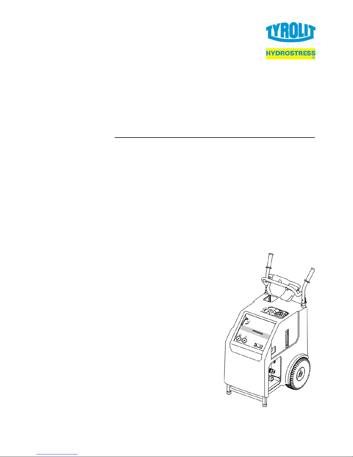
Drive Unit PPH25RR***
Index 000

Operating Instructions
10983823 en / 17.7.07
Manufacturer's address:
TYROLIT Hydrostress AG
Witzbergstrasse 18
CH-8330 Pfäffikon
Switzerland
Phone +41 (0) 44 / 952 18 18
Fax +41 (0) 44 / 952 18 00
TYROLIT Hydrostress AG reserves the right to make technical changes
without prior notice.
Copyright © 2007 TYROLIT Hydrostress AG, CH-8330 Pfäffikon ZH
All rights reserved, in particular the copying and translation rights.
The reprinting of these Operating Instructions, including extracts, is prohib-
ited. No part of these Operating Instructions may be reproduced in any
form whatsoever or be processed, copied or distributed using electronic
systems without the written permission of TYROLIT Hydrostress AG.

Operating Instructions Overview
PPH25RR*** / 000 I (II)
Overview
Page
0 Introduction 1
0.1 Congratulations!- - - - - - - - - - - - - - - - - - - - - - - - - - - - - - - 1
0.2 Validity of these Operating Instructions - - - - - - - - - - - - - - 2
0.3 Standards - - - - - - - - - - - - - - - - - - - - - - - - - - - - - - - - - - - 2
0.4 Delimitation of the system- - - - - - - - - - - - - - - - - - - - - - - - 2
1 Product description 1
1.1 Application - - - - - - - - - - - - - - - - - - - - - - - - - - - - - - - - - - 1
1.2 Safety measures - - - - - - - - - - - - - - - - - - - - - - - - - - - - - - 1
1.3 Operating instructions for connectable equipment- - - - - - - 1
1.4 Name plate - - - - - - - - - - - - - - - - - - - - - - - - - - - - - - - - - - 1
1.5 Information sign- - - - - - - - - - - - - - - - - - - - - - - - - - - - - - - 2
1.6 EC Declaration of Conformity - - - - - - - - - - - - - - - - - - - - - 3
1.7 Technical data - - - - - - - - - - - - - - - - - - - - - - - - - - - - - - - - 4
1.8 Hydraulics - - - - - - - - - - - - - - - - - - - - - - - - - - - - - - - - - - - 5
1.9 Electrical equipment- - - - - - - - - - - - - - - - - - - - - - - - - - - - 6
1.10 Water - - - - - - - - - - - - - - - - - - - - - - - - - - - - - - - - - - - - - - 7
1.11 Noise exposure (noise level)- - - - - - - - - - - - - - - - - - - - - - 7
1.12 Scope of supply- - - - - - - - - - - - - - - - - - - - - - - - - - - - - - - 7
1.13 Country list for radio transmission frequency- - - - - - - - - - - 8
2 Safety instructions 1
2.1 General- - - - - - - - - - - - - - - - - - - - - - - - - - - - - - - - - - - - - 1
2.2 General safety rules- - - - - - - - - - - - - - - - - - - - - - - - - - - - 1
2.3 Safety principles - - - - - - - - - - - - - - - - - - - - - - - - - - - - - - 2
2.4 Responsibility - - - - - - - - - - - - - - - - - - - - - - - - - - - - - - - - 3
2.5 Generally applicable warnings of residual dangers - - - - - - 5
3 Design and function 1
3.1 Design - - - - - - - - - - - - - - - - - - - - - - - - - - - - - - - - - - - - - 1
3.2 Function - - - - - - - - - - - - - - - - - - - - - - - - - - - - - - - - - - - - 2
3.3 Radio remote control - - - - - - - - - - - - - - - - - - - - - - - - - - - 4
4 Controls and displays 1
4.1 Controls - - - - - - - - - - - - - - - - - - - - - - - - - - - - - - - - - - - - 1
4.2 Electric controls - - - - - - - - - - - - - - - - - - - - - - - - - - - - - - - 2
4.3 Displays - - - - - - - - - - - - - - - - - - - - - - - - - - - - - - - - - - - - 4
5Operation 1
5.1 Personnel qualifications - - - - - - - - - - - - - - - - - - - - - - - - - 1
5.2 System requirements - - - - - - - - - - - - - - - - - - - - - - - - - - - 1
5.3 Preparatory operations - - - - - - - - - - - - - - - - - - - - - - - - - - 2
5.4 Working - - - - - - - - - - - - - - - - - - - - - - - - - - - - - - - - - - - - 7
5.5 After the work - - - - - - - - - - - - - - - - - - - - - - - - - - - - - - - - 11
6 Servicing 1
6.1 Servicing and maintenance table- - - - - - - - - - - - - - - - - - - 1

Overview Operating Instructions
II (II) PPH25RR*** / 000
7 Corrective maintenance 1
7.1 Troubleshooting - - - - - - - - - - - - - - - - - - - - - - - - - - - - - - - 1
7.2 Storage - - - - - - - - - - - - - - - - - - - - - - - - - - - - - - - - - - - - - 4
8 Transport 1
8.1 Transport- - - - - - - - - - - - - - - - - - - - - - - - - - - - - - - - - - - - 1
8.2 Safety instructions - - - - - - - - - - - - - - - - - - - - - - - - - - - - - 1
8.3 Crane shackles and transport handles - - - - - - - - - - - - - - - 2
9 Disposal 1
9.1 General - - - - - - - - - - - - - - - - - - - - - - - - - - - - - - - - - - - - - 1
9.2 Disposal regulations - - - - - - - - - - - - - - - - - - - - - - - - - - - - 2
9.3 Disposal of the Drive Unit PPH25RR*** - - - - - - - - - - - - - - 2

Operating Instructions Introduction
PPH25RR*** / 000 0-1
0 Introduction
0.1 Congratulations!
You have decided to purchase a tried and tested TYROLIT
Hydrostress AG system and have thus acquired a highly sophisticated and
reliable state-of-the-art unit.
Thanks to the emphasis we place on quality assurance, your TYROLIT
Hydrostress AG system is another top-of-the-range Swiss product:
• High performance
• Reliable operation
• High portability
• Easy handling
• Low maintenance costs
Only original TYROLIT Hydrostress AG spare parts can guarantee quality
and interchangeability.
In the case of neglected or inappropriate maintenance, we will be unable
to accept the warranty commitment as specified in our terms of delivery.
Any repair work must be carried out by trained personnel only.
If you need more details about how to keep your TYROLIT Hydro stress AG
system in perfect condition, please con tact our after-sales service fo r further information.
We hope that working with your TYROLIT Hydrostress AG system will be
a problem-free and fault-free experience.
TYROLIT Hydrostress AG
Management
Copyright © TYROLIT Hydrostress AG, May 2007
TYROLIT Hydrostress AG
Witzbergstrasse 18
CH-8330 Pfäffikon
Switzerland
Phone +41 (0) 44 / 952 18 18
Fax +41 (0) 44 / 952 18 00

Introduction Operating Instructions
0-2 PPH25RR*** / 000
0.2 Validity of these Operating Instructions
This manual is only valid for the following system:
Drive Unit PPH25RR***
0.3 Standards
These Operating Instructions have been prepared in accordance with the
CE Machinery Directive Appendix I and with the relevant standar ds in force
at the time of printing.
0.4 Delimitation of the system
These Operating Instructions describe the use of the Drive Unit
PPH25RR***.
Operating Instructions Product description
PPH25RR*** / 000 1-1
1 Product description
1.1 Application
The Drive Unit PPH25RR*** has been designed as a component for the following concrete processing systems:
• Hydraulic wall saw systems
• Hydraulic diamond wire saw systems
• Hydraulic core drilling systems
• Hydraulic chainsaws
The applicable mandatory limitations on use and other parameters are con -
tained in Chapter 1 "Technical data" 1.7, 1-4
1.2 Safety measures
Any use other than for the intended purpose (see Chapte r 1.1 , 1-1) constitutes abuse or misuse.
1.3 Operating instructions for connectable
equipment
In order to ensure safety in the work place and in dan ger ar eas, as we ll as
the safe operation of connectable equipment, the relevant Operating Instructions must in all cases be followed.
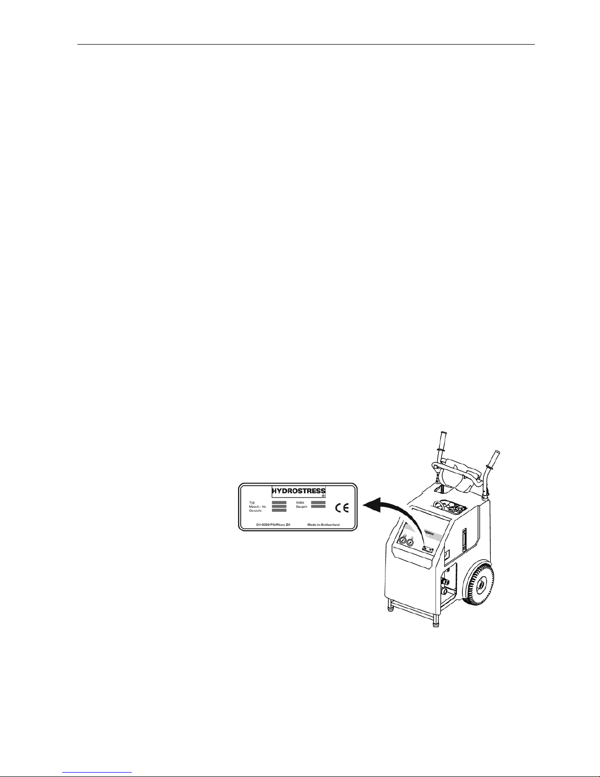
1.4 Name plate
Fig. 1-1 Name plate
Product description Operating Instructions
1-2 PPH25RR*** / 000
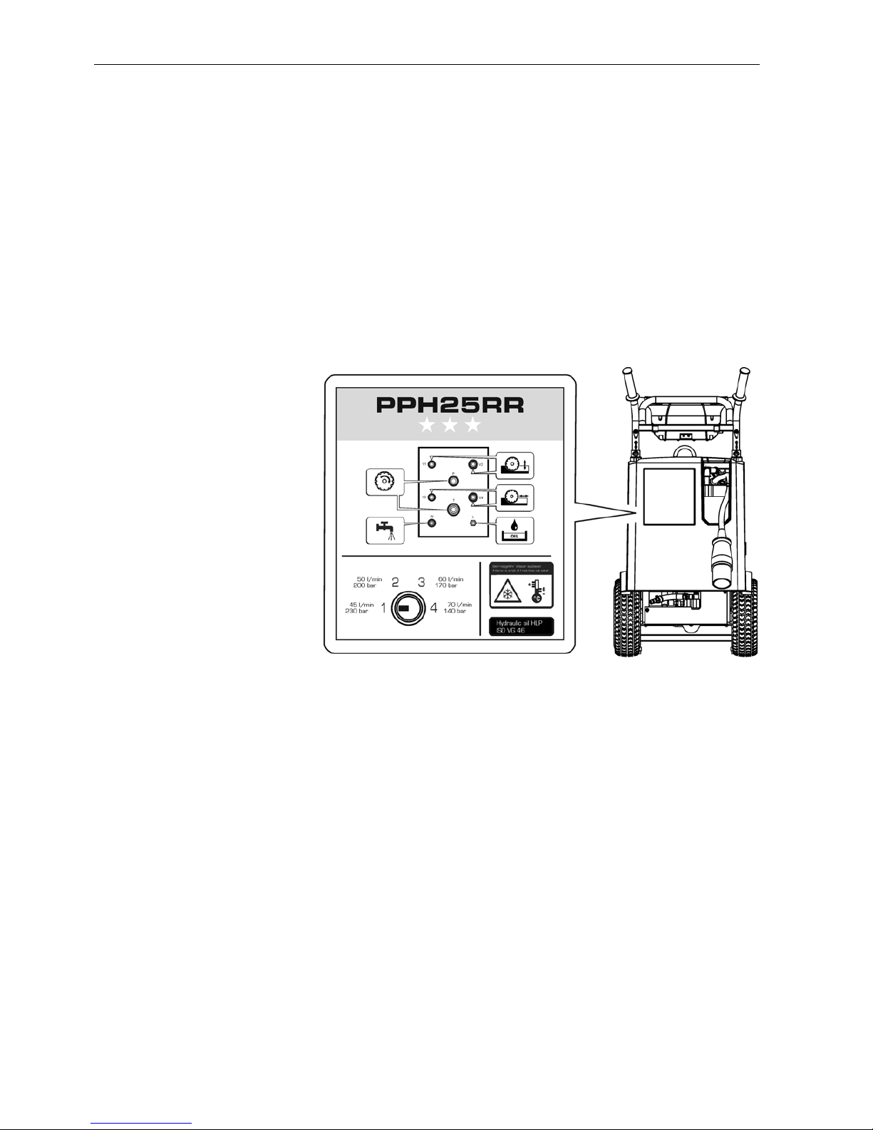
1.5 Information sign
Attached to the plastic hood is an information sign containing the following
information:
• Hose connections
(For a description see "Chapter 5" 5.3.2.1, 5-2)
• Pressure stages
(For a description see "Chapter 5" 5.4.3, 5-8)
• Risk of frost
(For a description see "Chapter 6" 6.1.1, 6-2)
• Hydraulic oil
(For a description see "Chapter 6" 6.1.2.1, 6-2)
Fig. 1-2 Information sign

Operating Instructions Product description
PPH25RR*** / 000 1-3
1.6 EC Declaration of Conformity
We declare under our own liability that this product complies with the following directives and standards:
1.6.0.1 Directive applied:
Machinery Directive 2006/42/EC
EC EMC Directive 89/336/EC
EC Low Voltage Directive 73/23/EC
1.6.0.2 Standards applied:
Description Hydraulic drive unit
Type designation Drive Unit PPH25RR***
Year of construction 2007
EN 12100-1
EN 12100-2
Safety of machinery – Basic concepts, general design
principles
EN 294 Safety of machinery – Safety distances to prevent upper limbs
reaching danger areas
EN 349 Safety of machinery – Safety distances to avoid crushing of
body parts
EN 982 Safety of machinery
Safety requirements of safety systems and their components Hydraulics
EN 60204-1Safety of machinery - Electrical equipment of machines
Product description Operating Instructions
1-4 PPH25RR*** / 000
1.7 Technical data
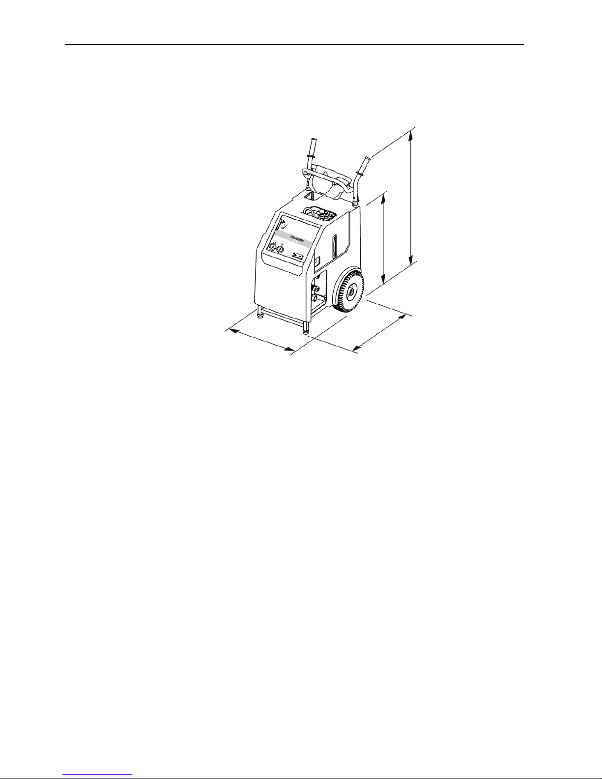
1.7.1 Dimensions
Fig. 1-3 Dimensions
1.7.2 Weight
Operating weight 160 kg
1.7.3 Tyres
Wheel Ø 30 cm
Operating pressure 3 bar
65 cm
105 - 120 cm
75 cm
55 cm

Operating Instructions Product description
PPH25RR*** / 000 1-5
1.8 Hydraulics
1.8.1 Main circuit
Main circuit 3 pumps
Flow rates can be set to 45 / 50 / 60 / 70 l/min., depending on the cutting
tool speed required
Flow rates and pressures
Stage I 45 l/min 230 bar
Stage II 50 l/min 200 bar
Stage III 60 l/min 170 bar
Stage IV 70 l/min 140 bar
Same power in all stages
1.8.2 Feed circuits
Feed circuits: 1 pump
Two hydraulic feed outputs which can be regulated independently of each
other, controlled using radio remote control.
1.8.3 Oil tank
Oil tank volume: 10 litres
Filter quality: 20 µm
1.8.4 Return oil filter
Type: Tank-mounted filter
1.8.5 Oil cooling
Oil cooler: Water/oil heat exchanger
1.8.6 Couplings and hoses
Plug-in couplings Type FD and FF, non-drip
Hoses Length 8m (filled with hydraulic oil)
1.8.7 Oil quality
TYROLIT Hydrostress AG recommends:
Hydraulic oil: HLP/ISO VG 46
Product description Operating Instructions
1-6 PPH25RR*** / 000
1.9 Electrical equipment
1.9.1 Different voltages
For countries where different mains networks operate the following types
are available:
Drive Unit PPH25RR*** 380-420 V 50 Hz
Drive Unit PPH25RR*** 420-480 V 60 Hz
1.9.2 Motor
Electric motor water-cooled
Power supply 3 P / LNPE 380 - 420 V / 50 Hz
420 - 480 V / 60 Hz
Current consumption 380 - 420 V / 50 Hz 40 A
420 - 480 V / 60 Hz 38 A
Output P1 25 kW / P2 21 kW
Speed at 50 Hz 2910 rpm
at 60 Hz 3480 rpm
1.9.2.1 Motor protection
Thermal protection Winding thermostat
Electrical protection Thermal relay
1.9.2.2 Cooling
Water cooling Cooling channels in the aluminium
Throughput of cooling water min. 6 l/min at max. 25° C
Water connection min. 2 bar, max. 6 bar
Information
Electrical data are only valid for the installed loads
3 P / LNPE 400 VAC / 50 Hz
Warning
A danger will arise if the Drive Unit PPH25RR*** is operated with a
different mains network voltage.
The details on the name plate must correspond to the mains network values (voltage and frequency).
Damage may be caused to the unit if it is connected to a different
voltage; there is also a risk of fire and personal injury.

Operating Instructions Product description
PPH25RR*** / 000 1-7
1.9.2.3 Protection class
IP 65
1.9.2.4 Internal control voltage (valve control)
24V / DC
1.9.2.5 Secondary socket
Connections 2 sockets 230V / 10A
with fault current tripping at 10 mA
1.10 Water
Pressure min. 2 bar to max. 6 bar
Quantity min. 6 l/min at max 25°C
1.11 Noise exposure (noise level)
Depending on the working environment and the connected device, the
Drive Unit PPH25RR*** can produce high noise levels during operation.
1.11.0.1 Noise level measurement
Noise level measured at the ear of the operator 0.5 m from the Drive Unit
PPH25RR***; noise power level according to ISO 3744; drive unit only;
highest value taken from all operating states at full load; mean values from
three series of measurements.
Noise level 83 dB (A) noise power level 92 dB (A)
1.12 Scope of supply
• Drive Unit PPH25RR***
• Radio remote control
• Water purge pump
• Operating Instructions / Spare parts list
Danger
Noise danger
When operating the PPH25RR*** drive unit, the wearing of hearing
protection is mandatory at all times.
If this instruction is not followed irreparable hearing damage may
result.

Product description Operating Instructions
1-8 PPH25RR*** / 000
1.13 Country list for radio transmission frequency
Fig. 1-4 Country list for radio transmission frequency
*** On request
Country Frequency
MHz
Country Frequency
MHz
Australia 434 Mexico 458
Belgium 434 New Zealand 434
Bolivia 434 Netherlands 434
Brazil 434 Norway 434
Brunei 434 Austria 434
Bulgaria 434 Poland 434
China 419 Portugal 434
Denmark 434 Puerto Rico 458
Germany 434 Romania 434
Finland 434 Russia 434
France 434 Sweden 434
Greece 434 Switzerland 434
Great Britain 434 Singapore 434
Hong Kong 458 Slovenia 434
India, Mumbai 434 Spain 434
India, New Delhi 434 South Korea 447
Indonesia 434 South Africa 434
Ireland 434 Taiwan 480
Iceland 434 Thailand 434
Italy 434 Turkey 434
Japan 429 Ukraine 434
Canada 458 USA 458
Croatia 434 USA (South America) 434
Liechtenstein 434 Venezuela 434
Lithuania 434 United Arab Emirates 434
Luxembourg 434 Philippine 434
Malaysia 434

Operating Instructions Safety instructions
PPH25RR*** / 000 2-1
2 Safety instructions
2.1 General
All persons who work on and with the Drive Unit PPH25RR*** have a duty
to read and understand the Operating Instructions.
2.1.1 Observance of the safety instructions
The Drive Unit PPH25RR*** has been inspected before being shipped and
is delivered in perfect condition. TYROLIT Hydrostress AG does not accept
any liability for damage which is caused by failure to observe the instructions and information provided in the Operating Instructions. This a pplies in
particular to:
• Damage caused by improper use and operator error.
• Damage caused by failure to observe safety-related information in the
Operating Instructions or shown on the warning signs attached to the
machine.
• Damage caused by defective or neglected maintenance work.
Independently performed conversions and alterations may affect safety
and are not permitted.
2.2 General safety rules
2.2.1 Statutory provisions
The generally applicable national and local safety and accident prevention
provisions and the supplementary operator regulations must be followed
and complied with.
2.2.2 Inspection and maintenance obligation
The operator is under an obligation to use the Drive Unit PPH25RR*** only
when it is in a perfect and undamaged condition. The maintenance intervals shown in the Operating Instructions must be adhered to without fail.
Malfunctions and mechanical damage must be rectified without delay.
2.2.3 Spare parts
Only TYROLIT Hydrostress A G original spare parts may be used. Othe rwise, damage can be caused to the Drive Unit PPH25RR*** or other property and may result in personal injury.
2.2.4 Power connections
The Drive Unit PPH25RR*** must be connected and coupled in accordance with the Operating Instructions.

Safety instructions Operating Instructions
2-2 PPH25RR*** / 000
2.3 Safety principles
2.3.1 Delimitation of the safety concept
The Drive Unit PPH25RR*** does not affect the safety concept of the connected systems, equipment and installations.
2.3.2 Safety elements
Protection from live electrical parts
All functional units containing parts which carry hazardous voltages are
shock-protected by suitable covers.
2.3.3 Removal of protective devices
Protective devices may only be removed if the unit has been switched off,
disconnected from the mains and is at standstill. Safety components, in
particular, may only be removed and refitted by authorised personnel, see
"Chapter 2" 2.4.1, 2-3.
Before switching the Drive Unit PPH25RR*** back on again, the safety elements must be checked to ensure correct operation.
2.3.4 Safety measures (organisational)
2.3.4.1 Product monitoring obligation
Operating personnel must notify changes in operational behaviour or safety-related components to a responsible person or the manufacturer, immediately.
2.3.4.2 Location of the Operating Instructions
A copy of the Operating Instructions must be available to staff at all times
at the place of use of the equipment.

Operating Instructions Safety instructions
PPH25RR*** / 000 2-3
2.4 Responsibility
2.4.1 Authorised personnel
Work on or with the TYROLIT Hydrostress AG machines or systems may
only be performed by authorised personnel. Personnel are considered by
TYROLIT Hydrostress AG to be authorised if they meet the necessary
training and know-how requirements and they have been assigned a precise functional role.
The personnel qualifications for the corresponding work are contained in
the introduction under "General" of the respective chapters.
2.4.2 Manufacturer
TYROLIT Hydrostress AG or a company expressly nominated by TYROLIT Hydrostress AG is deemed to be the manufacturer of the products
supplied by TYROLIT Hydrostress AG. Within the context of an integrated
quality and safety control system, the manufacturer is entitled to request
from the operator information about the products.
2.4.3 Operator (owner)
The operator named by TYROLIT Hydrostress AG is the primary, legal entity responsible for the correct us e of the product and for the tr aining and
assignment of the authorised personnel. The operator sets out the mandatory skills and level of training of the authorised personnel for his company.
2.4.4 Operator (user)
User is the term employed by TYROLIT Hydrostress AG to designate a
person who independently performs the following work:
• Sets up TYROLIT Hydrostress AG machines or systems for tasks according to the intended purpose.
• Performs tasks independently and monitors these.
• Locates malfunctions and initiates or performs troubleshooting.
• Carries out servicing and simple maintenance.
• Monitors the correct functioning of the safet y device s.
2.4.5 Service engineer
Service engineer is a term used by TYROLIT Hydrostress AG to designate
a person who independently performs the following work:
• Installs TYROLIT Hydrostress AG machines and systems and controls
their correct application.
• Makes adjustments to machines and systems for which special access
rights are required.
• Performs repairs, complex service work and maintenance work.

Safety instructions Operating Instructions
2-4 PPH25RR*** / 000
2.4.6 Qualification and training
2.4.6.1 Operator (owner)
• A technically trained person in a management position.
• Has relevant experience in personnel management and danger assessment.
• Has read and understood the "Safety instructions" chapter.
2.4.6.2 Operator (user)
• Has trained as a concrete cutting expert or has professional experience.
• Has received an introduction (basic training) to the operation of the
TYROLIT Hydrostress AG machines and systems from a service engineer.
• Has read and understood Chapter 2 "Safety instructions".
2.4.6.3 Service engineer
• Has specialist professional training (mechanical / electrotechnical).
• Has attended specialist courses at TYROLIT Hydrostress AG.
• Has read and understood the "Safety instructions" chapter.

Operating Instructions Safety instructions
PPH25RR*** / 000 2-5
2.5 Generally applicable warnings of residual
dangers
Danger
Electric shock due to defective electronic equipment.
The electrotechnical equipment must be checked prior to each use
and from time to time during prolonged use. Defective parts, such
as e.g. cables and plugs, must be replaced immediately in the deenergized state by electrotechnically trained personnel.
Failure to comply with this regulation may lead to serious physical
injury or death. Secondary damage such as fires may also occur.
Warning
Danger of allergic reactions if skin comes into contact with hydraulic oil.
Persons who have an allergic reaction to hydraulic oil must wear
protective gloves and goggles when carrying o ut work whe re they
come into contact with hydraulic oil. Any areas of the skin affected
must be rinsed immediately with copious amounts of water.
Failure to observe this regulation may result in allergic reactions or
injury to the eyes.

Safety instructions Operating Instructions
2-6 PPH25RR*** / 000

Operating Instructions Design and function
PPH25RR*** / 000 3-1
3 Design and function
3.1 Design
Fig. 3-1 Main components
1 Hydraulic unit 10 Antenna
2 Oil cooler 11 Oil level indicator
3 Pressure gauge 12 Radio receiver
4 Water valve 13 Electrical connection
5 Suspension shackle 14 Electrical box
6 Electric motor 15 Wheel
7 Radio remote control 16 Hood
8 Transport handle with hose bracket 17 Oil tank
9 Pump assembly
1
5
6
3
7
4
8
9
10
11
12
13
14
17
2
15
16

Design and function Operating Instructions
3-2 PPH25RR*** / 000
3.2 Function
3.2.1 Hydraulic circuit diagram
Fig. 3-2 Hydraulic circuit diagram
1 Electric motor 18 Leak-oil nipple
2 Pump assembly 19 Coupling
3 Proportional valve 0-260 bar 20 Nipple
4 Check valve 21 Coupling
5 Pressure relief valve 22 Nipple
6 Pressure gauge 0-400 bar 23 Coupling
7 Oil and water cooler 24 Water valve
8 Aeration filter 25 Pressure valve 20 bar
9 Oil level 26 Proportional valve 5-120 bar
10 Return filter 27 2/2-way seat valve
11 Screw plug 28 Bijour-nozzle
12 2/2-way seat valve 29 Pressure-maintaining valve
13 4/3-way valve 30 Check valve
14 Pressure relief valve 150 bar 31 Water filter
15 Pressure gauge 0-250 bar 32 Water valve
16 Nipple 33 Radial piston pump
17 Coupling

Operating Instructions Design and function
PPH25RR*** / 000 3-3
3.2.2 Wiring diagram
Fig. 3-3 Wiring diagram
1 Elec. box 8 EMERG. STOP
2 Reversing switch 9a Hour counter
3 Contactor 9b Rotation lock
4 Thermal relay 10 Phase sequence relay
5 Interlock 11 Time relay
6 Circuit breaker 12 Connector CEE 63/5
7a Device protective switch 13 Relay
7b Protective hood 14 Power supply unit

Design and function Operating Instructions
3-4 PPH25RR*** / 000
3.3 Radio remote control
3.3.1 Design
Fig. 3-4 Remote controller
1 Controls
2 Plastic housing
3.3.1.1 Accessories
Fig. 3-5 Accessories
1 2x interchangeable battery
2 Battery charger
3 Cable insert
4 Battery insert
3.3.2 Function
The radio remote control allows a secure, simple and mobile method of
working. The operator can at all times be in a position where he has a full
view of the unit during operation.
Warning
The battery charger is exclusively for recharging the interchangeable rechargeable battery. The battery insert and the cable insert must not be
inserted.
2
1
2
1
3
4

Operating Instructions Controls and displays
PPH25RR*** / 000 4-1
4 Controls and displays
4.1 Controls
Fig. 4-1 Controls
1 Water and hydraulic couplings 6 EMERG. STOP
2 Safety socket 7 Water valve
3 Schuko socket 8 Suspension shackle
4 Forward/reverse switch 9 Remote controller
5 Device protective switch 10 Cable connection of remote controller
4.1.1 Radio remote control
Fig. 4-2 Radio remote control
1 Locking switch 7 Pressure stage selector switch
2 Pilot lamp (radio & battery) 8 Water In / Out
3 EMERG. STOP 9 Main motor potentiometer
4 Main switch of drive unit 10 Main motor On / Off
5 Start switch 11 Feed motor potentiometer
6 Feed joystick
1
2
5
3
4
6
7
8
9
10
3
1
4
68
9
7
11
2
5
10

Controls and displays Operating Instructions
4-2 PPH25RR*** / 000
4.2 Electric controls
4.2.1 Secondary sockets
The Drive Unit PPH25RR*** is equipped with 2 x 230V / 10 A seco ndary
sockets with fault current tripping at 10 mA.
The secondary sockets may only be used with a neutral conductor.
Fig. 4-3 Secondary sockets
1 On / Off switch 3 Safety socket
2 Test button 4 Schuko socket
4.2.1.1 Safety socket
The safety socket has integral residual current protection and is the active
personnel safety device. The operating principle of the safety socket is the
same as that of a residual current circuit breaker.
Monitoring
The safety socket must be checked monthly during operation. The check
can be performed with or without the plug inserted, as follows:
• The switch must be in the (I) position
• Press the Test button
– the switch must switch off (0 position)
• Push the switch back into the (I) position
4.2.1.2 Schuko socket
The Schuko socket is connected and protec te d via th e sa fet y s oc ke t.
Information
Equipment on which the safety socket interrupts the power circuit during
operation is defective and must be checked by an electrical engineer
and, if necessary, repaired.
1
3
2
4

Operating Instructions Controls and displays
PPH25RR*** / 000 4-3
4.2.2 Forward/reverse switch
If the phase position of the power supply to the site is wrong, the phases
can be turned.
4.2.3 Device protective switch
The device protective switch protects the secondary sockets and thereby
protects the devices connected to the sockets.
The device switch interrupts the circuit in the event of a current surge (more
than 13A). The circuit is restored by pressing the device switch.
4.2.4 Cable connection of remote controller
The radio remote control can be connected to the Drive Unit PPH25RR***
power supply by means of the cable insert.
4.2.5 EMERGENCY STOP
Pressing the EMERGENCY STOP button switches the system off and prevents the system being accidentally switched on again.
Fig. 4-4 EMERGENCY STOP
1 EMERG. STOP on the Drive Unit PPH25RR***
2 EMERG. STOP on the radio remote control
1
2

Controls and displays Operating Instructions
4-4 PPH25RR*** / 000
4.3 Displays
Fig. 4-5 Displays
1 Hour counter 4 Pressure gauge of main motor
2 Pilot lamp (radio & battery) 5 Oil level indicator
3 Pressure gauge of feed motors
4.3.1 Hour counter
The hour counter allows for precise observance of the service intervals.
Fig. 4-6 Hour counter
4.3.2 Pilot lamp (radio & battery)
Fig. 4-7 LED pilot lamp
The LED pilot lamp on the radio remote control flashes green to indicate
operational readiness. When the battery voltage becomes low, the colour
changes from green to red.
1
3
5
4
2

Operating Instructions Controls and displays
PPH25RR*** / 000 4-5
4.3.3 Pressure gauge
Fig. 4-8 Pressure gauge
1 Pressure gauge of main motor (0 bar to 400 bar)
2 Pressure gauge of feed motors (0 bar to 250 bar)
4.3.4 Oil level indicator
Fig. 4-9 Oil level indicator
Information
The quantity of oil between oil MIN and oil MAX is 1.5 litres.
Different types of hydraulic oil should not be mixed together, otherwise
the oil will age prematurely.
Recommended hydraulic oil: HLP / ISO VG 46
1
2
MIN.
MAX.

Controls and displays Operating Instructions
4-6 PPH25RR*** / 000
Operating Instructions Operation
PPH25RR*** / 000 5-1
5 Operation
5.1 Personnel qualifications
The Drive Unit PPH25RR*** must not be operated by unauthorised personnel. Personnel are only authorised if they meet the following requirements.
• Have trained as a concrete c utting expert or have profes sional experience.
• Have received an introduction (basic training) to the operation of the
Drive Unit PPH25RR*** from a service engineer.
• Have read and understood chapter 2 "Safety instructions".
5.2 System requirements
5.2.1 Connectable equipment
All hydraulic units that are designed for the pressure and delivery volume
of the Drive Unit PPH25RR**** (see "Chapter 1" 1.8, 1-5).
Warning
A danger will arise if the Drive Unit PPH25RR*** is operated with a
different mains network voltage.
The details on the name plate must correspond to the mains network values (voltage and frequency).
The system may be damaged by connecting it to a diff erent voltage.
There is also a danger of fire and injury.
Information
The Drive Unit PPH25RR*** is one of a series of drive pr oducts available
from TYROLIT Hydrostress AG.
In order to allow expansion of your Drive Unit PPH25RR*** with suitable
devices to create an hydraulic saw or drilling system with optimum performance, please talk to TYROLIT Hydrostress AG.

Operation Operating Instructions
5-2 PPH25RR*** / 000
5.3 Preparatory operations
5.3.1 Visual inspection
Before starting work always complete the following visual inspections:
• Is the power supply earthed, fitted with a neutral conductor and a residual current circuit breaker?
• Does the mains network have fuse protection for a minimum of 45A?
• Is the cable cross section 5x6mm² (from 25m to 50m / 5x10mm²)?
• Is the water line properly connected to the Drive Unit PPH25RR***?
• Is there sufficient oil in the Drive Unit PPH25RR***?
• Is there any damage to cables or plugs?
• Has the EMERGENCY STOP been reset?
5.3.2 Connecting the Drive Unit PPH25RR***
5.3.2.1 Connecting the hoses
Information
Ensure that the water supply is not interrupte d while work is in progress.
Warning
Danger from uncontrolled movements and uncontr olled escape of
oil.
Never connect or disconnect hoses while the drive unit is runnin g.
Failure to observe this regulation may result in cut wounds or injury to body parts as well as damage to property.

Operating Instructions Operation
PPH25RR*** / 000 5-3
5.3.2.2 Hose connections
Fig. 5-1 Hose connections
1 Couplings of main motor
2 Water connection
3 Couplings of feed motor 1
4 Couplings of feed motor 2
5 Leak-oil connection (hydraulic motor Gr.3)
Proceed as follows:
• Visual inspection
Check:
– Oil leaks from hoses and couplings
– Couplings for damage and contamination
– Hoses for damage
• Push the hose coupling on to its counterpart until you hear it "click".
• Twist the locking ring of the coupling.
5.3.2.3 Release pressure in the Drive Unit PPH25RR***
Proceed as follows:
• Turn the forward/reverse switch on the Drive Unit PPH25RR*** to posi-
tion 1 (2).
• Switch on the radio remote control by means of the Start switch.
• Press the main switch once, on the radio remote control.
• Briefly push the feed joystick in all directions.
Information
If hoses cannot be connected or this cannot be done easily, they are under pressure. Release pressure in hoses via the pressure relief device.
Release pressure in the Drive Unit PPH25RR***, see "Chapter 5"
5.3.2.3, 5-3.
Never use force to connect couplings!
1
2
3
4
5

Operation Operating Instructions
5-4 PPH25RR*** / 000
5.3.3 Radio remote control provision
5.3.3.1 Power sources
The radio remote control can be operated using a rechargeable battery,
disposable battery or via cable.
Rechargeable battery operation:
The interchangeable rechargeable battery is inserted at the housing base.
The operating period with a fully charged battery is approximately 12 hours.
The reception distance is 25 m.
Cable operation:
The cable insert included in the scope of supply allows connection of the
remote controller to the Drive Unit PPH25RR***. The cable length is 10 m.
Cable operation makes it possible to work in areas where radio operation
is not allowed (e.g. hospitals).
Fig. 5-2 Cable operation
Battery operation:
The battery insert included in the scope of supply allows operation with
three 1.5 V AA batteries. The reception distance is 25 m.
Information
The transmitter and receiver are a pair of matched units. They cann ot be
used with other devices.
Information
When working with the cable connection, all control signals are transmitted via the electric cable.

Operating Instructions Operation
PPH25RR*** / 000 5-5
5.3.4 EMERGENCY STOP
In danger situations the EMERGENCY STOP button must be pressed immediately.
Fig. 5-3 EMERGENCY STOP
1 EMERG. STOP on the Drive Unit PPH25RR***
2 EMERG. STOP on the radio remote control
Deactivating EMERGENCY STOP
Fig. 5-4 Deactivating EMERGENCY STOP
Proceed as follows:
• The following controls must be moved into the 0 position:
- Feed joystick (3)
- Main motor On/Off (5)
• Turn the EMERG. STOP button (1 / 2) clockwise.
• Push the main switch (4) to the ON position.
Information
If the EMERG. STOP is activated on the radio remote control, the LED
pilot lamp flashes quickly.
1
2
1
2
3
4
5

Operation Operating Instructions
5-6 PPH25RR*** / 000
5.4 Working
5.4.1 Starting the Drive Unit PPH25RR***
Proceed as follows:
• Check that the EMERG. STOP buttons on the radio remote control and
on the Drive Unit PPH25RR*** are deactivated.
• Move the controls shown below on the remote controller in to the 0 p osition.
Fig. 5-5 0 position
1 Start switch
2 Feed joystick
3 Main motor On/Off
• Turn the forward/reverse switch on the Drive Unit PPH25RR*** to position 1.
• Switch on the radio remote control by means of the Start switch.
– Pilot lamp lights up red, first of all
– A signal tone sounds simultaneously
– Pilot lamp lights up green
– Second signal tone sounds
– Pilot lamp flashes green
• Push the main switch on the radio remote control twice, into the ON position.
– The electric motor starts
Information
The Drive Unit PPH25RR*** should only be switched on in a level and
upright position. If the surface has an incline, secure the drive unit to prevent rolling away.
Information
If the electric motor does not start, the forward/reverse switch on the
Drive Unit PPH25RR*** must be turned to position 2.
3
2
1

Operating Instructions Operation
PPH25RR*** / 000 5-7
• Press the Water On/Off button on the remote controller to I
• Open the water valve on the Drive Unit PPH25RR***
– water emerges from the cutting tool
• The Drive Unit PPH25RR*** is ready for operation
5.4.2 Soft start
The Drive Unit PPH25RR*** provides the option of a soft start.
The soft start is used mainly for diamond wire sawing.
Proceed as follows
• Start the Drive Unit PPH25RR***,
see "Chapter 5" 5.4.1, 5-6
• Turn the main motor potentiometer to the 0 position
• Select the desired pressure stage,
see "Chapter 5", 5.4.3, 5-8
• Turn the main motor potentiometer slowly to
100% power
Information
If the Drive Unit PPH25RR*** is switched off after the electric motor has
once been started up, in order to start up again it is only necessary to
press the main switch on the remote controller just once more.
Operation Operating Instructions
5-8 PPH25RR*** / 000
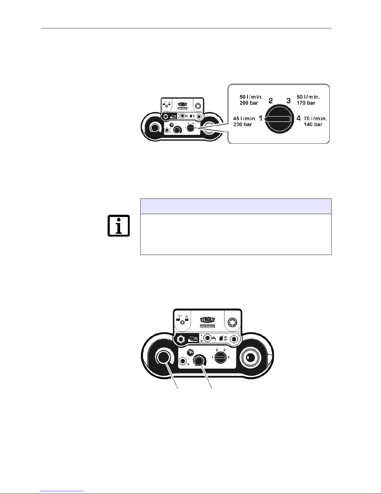
5.4.3 Selecting the pressure stage
Once the Drive Unit PPH25RR*** has been started properly, you can select
the pressure stage.
Fig. 5-6 Selecting the pressure stage
Proceed as follows
• Set the pressure stage selector switch to the desired pressure stage and
turn the main motor potentiometer from 0 to 100%.
5.4.4 Power control
The power of the main motor and the feed mot or is controlled via the potentiometer.
Fig. 5-7 Potentiometers
1 Feed motor potentiometer
2 Main motor potentiometer
Information
The pressure stages can be freely changed and selected during the
work operation. When changing the pressure stage, the cutting tools
should not be under load.
To ensure the optimal tool speeds, the data for the relevant connected
devices must be taken into consideration.
1
2

Operating Instructions Operation
PPH25RR*** / 000 5-9
5.4.5 Feed movements
The feed motors for the travel motion and the swivelling can only be controlled individually by means of the feed joystick.
Fig. 5-8 Feed
ATravel feed
B Swivel feed
5.4.6 Feed locking
So that the joystick does not have to be held in position during the travel
feed motion, the travel feed can be locked.
Proceed as follows
• Push the joystick in the desired travel d irection and, at the same time,
press the locking switch.
• When the joystick and the locking button are released, the feed is
locked.
Information
In order to release the feed lock, move the joystick slightly in any desired
direction.

Operation Operating Instructions
5-10 PPH25RR*** / 000
5.4.7 Shutting down the Drive Unit PPH25RR***
Proceed as follows
• Switch off the electric motor (main switch of radio remote control)
• Shut off the cooling water (Water On/Off button of radio remote control)
• Close the water valve on the Drive Unit PPH25RR***
• Turn the Start switch on the radio remote control into the 0 position
• Turn the forward/reverse switch on the Drive Unit PPH25RR*** to the 0
position
5.5 After the work
Proceed as follows:
• Unplug the mains plug (Drive Unit PPH25RR***)
• Uncouple the water supply on the Drive Unit PPH25RR***
• Open the water valve on the Drive Unit PPH25RR***
• Blow out the water from all the lines (purge pump)
• Uncouple the hydraulic hoses
• Clean the Drive Unit PPH25RR*** with water
Information
Only shut down the Drive Unit PPH25RR*** with the EMERGENCY
STOP in a genuine emergency.
Information
In order to prevent frost damage, if there is a risk of frost the entire water
system must be emptied and blown out upon finishing work or prior to
extended breaks in the work.

Operating Instructions Servicing
PPH25RR*** / 000 6-1
6 Servicing
6.1 Servicing and maintenance table
Before each start-up
Upon completion of work
Weekly
Annually
In the event of malfunction
In the event of damage
Hydraulic system Hydraulic hose inspection
(leakproof condition / cleanliness)
XX XX
Coupling inspection
(leakproof condition / cleanliness)
XX XX
Check oil level,
see "Chapter 4" 4.3.4, 4-5
XX X
Replace hydraulic oil,
see "Chapter 6" 6.1.2, 6-2
X
Water economy Water line
(leakproof condition / cleanliness)
XX XX
If there is a risk of frost, blow out the
water, see "Chapter 6" 6.1.1, 6-2
X
Mechanical Retighten accessible screws and nuts X X
Major service
First service after
100 operating hours
After every 200 operating
hours, thereafter
May only be carried out by
TYROLIT Hydrostress AG
or an authorised representative

Servicing Operating Instructions
6-2 PPH25RR*** / 000
6.1.1 Blowing out the water
6.1.2 Oil change
6.1.2.1 Oil quality
TYROLIT Hydrostress AG recommends:
Hydraulic oil: HLP / ISO VG 46
Other hydraulic oils can be used if they comply with the following specifications:
Information
In order to prevent damage from frost-cracks, if there is a risk of frost or
prior to extended breaks in work the cooling water must be blown out o f
the system. Use the TYROLIT purge pump No. 10982667.
Pour point: -42° C
Viscosity index: 170
Viscosity class: HLP VG 46 or ISO 3498 HV 46
Wear-protection according to DIN 51524 Part 3 (HV46)
Information
Different types of hydraulic oil should not be mixed together, otherwise
the oil will age prematurely.

Operating Instructions Servicing
PPH25RR*** / 000 6-3
6.1.2.2 Replacing hydraulic oil
In order to replace the hydraulic oil you will need:
• A collecting pan for the used hydraulic oil with a capacity of approx.
15 litres
• Open-ended spanner, size across flats 18 mm for the oil drain plug
• Approx. 10 litres of hydraulic oil
Fig. 6-1 Replacing hydraulic oil
1 Oil drain plug
Proceed as follows
• Place the collecting pan below the oil drain plug (1)
• Open tank cover
• Remove oil drain plug (1)
• Drain hydraulic oil completely
• Screw in oil drain plug (1)
• Fill tank with new hydraulic oil
• Bleeding the system
• Close the tank cover
• Dispose of waste hydraulic oil in accordance with local regulations
1

Servicing Operating Instructions
6-4 PPH25RR*** / 000
Bleeding the system
Proceed as follows
• Open tank cover
• Fill oil to maximum mark
• Do not refit the tank cover, yet
• Short-circuit the main circuit with hose
• Start the Drive Unit PPH25RR***,
see "Chapter 5" 5.4.1, 5-6
• Select the pressure stage 4,
see "Chapter 5" 5.4.3, 5-8
• Allow the Drive Unit PPH25RR*** to run for a maximum of 5 seconds
• Switch off the Drive Unit PPH25RR***,
see "Chapter 5" 5.4.7, 5-10
• Wait for 1 minute
• Repeat the start-up and shutdown process three times
• Check the oil level and top up the hydraulic oil as necessary
• Fit tank cover
• The system is now free of air
Information
Air must be bled from the system whenever the tank has been completely emptied and refilled.

Operating Instructions Corrective maintenance
PPH25RR*** / 000 7-1
7 Corrective maintenance
7.1 Troubleshooting
The following table will help you to narrow down and rectify the source of
the fault.
Fault Possible cause Solution
Drive Unit PPH25RR*** does not
run, although the mains cable is
connected
Forward/reverse switch in wrong
position
see "Chapter 5" 5.4.1, 5-6
Emergency stop has been activated Release emergency Stop,
see "Chapter 5" 5.3.4, 5-5
No voltage at drive unit because:
Automatic circuit breaker in
electric controller has tripped
Reset automatic circuit breaker
Mains cable is defective Replace the mains cable
No voltage at the power supply
(building site)
Check power supply
Power supply phases incorrectly
connected
Check power supply
Phase missing Check power supply
Remote controller not switched on
or controls in wrong position
see "Chapter 5" 5.4.1, 5-6
No radio connection Test with cable insert
Drive unit starts up, but then
switches off again
Fuse of building site power supply
trips
- Fuse protection too weak
- Change power supply
Incorrect voltage The details on the name plate must
correspond to the mains network
values (voltage and frequency).
No power, although electric motor is
running and valves are open
Motor runs in wrong direction Change direction of rotation with for-
ward/reverse switch
For drive unit with monitoring
Inform TYROLIT Hydrostress AG
after-sales service
Defective pump Have pump replaced by
TYROLIT Hydrostress AG
or an authorised representative
Defective toothed belt Have toothed belt replaced by
TYROLIT Hydrostress AG
or an authorised representative

Corrective maintenance Operating Instructions
7-2 PPH25RR*** / 000
The hydraulic oil is cloudy, light in
colour and the tank overflows
Defective oil cooler Inform TYROLIT Hydrostress AG
after-sales service
Warning: Do not continue operating
the unit, otherwise hydraulic elements could be damaged
Coupling leaks - Defective seal
- Defective coupling
- Replace seal
- Replace coupling
The drive unit stops suddenly Power supply interrupted because
electric motor or thermal relay has
overheated.
Reasons:
- Undervoltage at the power supply
- Overvoltage at the power supply
- Cross section of power supply
cable too small
- Water supply not correct
Check power supply,
see "Chapter 1" 1.9.1, 1-6
Check power supply,
see "Chapter 1" 1.9.1, 1-6
Use mains cable with correct cross
section, see "Chapter 5" 5.3.1, 5-2
Check water circuit,
see "Chapter 1" 1.10, 1-7
Defective plug connection Check plug connection
No radio connection - Replace the battery
- Work with cable insert
Main motor potentiometer does not
work
Defective potentiometer Note:
see "Chapter 5" 5.4.2, 5-7
TYROLIT Hydrostress AG
Inform the after-sales service
Defective proportional valve Inform TYROLIT Hydrostress AG
after-sales service
Defective pump Inform TYROLIT Hydrostress AG
after-sales service
No pressure build-up in feed circuit Defective potentiometer Inform TYROLIT Hydrostress AG
after-sales service
Defective proportional valve Inform TYROLIT Hydrostress AG
after-sales service
Defective pump Inform TYROLIT Hydrostress AG
after-sales service
Fault Possible cause Solution

Operating Instructions Corrective maintenance
PPH25RR*** / 000 7-3
If you are unable to remedy a fault, please call our service centre (see manufacturer's address on the reverse of the title page).
To guarantee a rapid and professional solution to the problem, it is important that you have prepared as follows before calling:
• Try to describe the fault as accurately as possible
• Note the type and index designation of your unit (name plate)
• Have the Operating Instructions close to hand
Fig. 7-1 Name plate
No water emerging Water line is blocked Clean the water line
Water valve on feed line is closed Open water valve
Insufficient water pressure Check water circuit,
see "Chapter 1" 1.10, 1-7
Defective water valve Inform TYROLIT Hydrostress AG
after-sales service
Water filter is blocked Clean the filter or inform
TYROLIT Hydrostress AG
after sales service
Fault Possible cause Solution

Corrective maintenance Operating Instructions
7-4 PPH25RR*** / 000
7.2 Storage
The Drive Unit PPH25RR*** consists partially of material which can corrode. If you take the unit out of service for an extended period, proceed as
follows:
• Blow out the water from the water lines
• Lightly oil the unit
• Store in a dry location

Operating Instructions Transport
PPH25RR*** / 000 8-1
8 Transport
8.1 Transport
The Drive Unit PPH25RR*** is a high-quality, technical device. Protect it
against transport damage:
• Do not place any parts on or against the Drive Unit PPH25RR***
• Protect the Drive Unit PPH25RR*** from impacts
• The Drive Unit PPH25RR*** must be secured against rolling away during transport
8.2 Safety instructions
It is essential to observe the following safety instructions, especially in relation to taking the Drive Unit PPH25RR*** out of service.
Danger
Danger from incorrect crane transport
Crane transport should only be carried out using the crane shackles provided.
Only undertake crane transport with serviceable building and mobile cranes.
Failure to observe this regulation may lead to serious physical injury, possibly even death, and to property damage.
Warning
Danger from the lifting of heavy loads.
Units which weight more than 30 kg must not be lifted without suitable equipment.
For transport, use the handles provided. Always keep handles
clean and free of grease.
Failure to adhere to this regulation may result in physical injury and
damage to property.

Transport Operating Instructions
8-2 PPH25RR*** / 000
8.3 Crane shackles and transport handles
Fig. 8-1 Crane shackles and transport handles
1 Crane shackles
2 Transport handles with hose bracket
Danger
Danger of falling parts.
When crane transport is used, the Drive Unit PPH25RR*** must be
transported alone, without the radio remote control and hoses.
Failure to observe this regulation may lead to serious physical injury, possibly even death, and to property damage.
1
2

Operating Instructions Disposal
PPH25RR*** / 000 9-1
9 Disposal
9.1 General
The operator can recycle or dispose of the Drive Unit PPH25RR*** himself
provided that he observes the statutory provisions. In order to dismantle
the unit correctly and to properly separate the materials, some knowledge
of mechanical procedures and knowledge about the differentiation of waste
materials is necessary.
Before proceeding, first of all read Chapter 2 "Safety instructions", 2-1 in
these Operating Instructions. Be sure also to observe all the danger information given here and follow the instructions on how to prevent personal
injury and damage to property.
9.1.1 Safety instructions
It is essential to observe the following safety instructions, especially in relation to disposal of the Drive Unit PPH25RR***.
9.1.2 Personnel qualifications
Personnel who carry out the work described in this chapter must meet the
following conditions:
• Have read and understood the safety instructions in "Chapter 2".
• Have completed their technical training (mechanical/electrotechnical)
and are in a position to differentiate the various mate r ial gr ou ps .
Danger
Danger of falling heavy parts.
When performing the types of work described in this chapter, it is
absolutely essential to wear the following personal protective
equipment: goggles, protective gloves and safety shoes.
It is essential to ensure that the work instructions and p rocedur es
described in this safety manual are followed.
Failure to observe this regulation may lead to serious physical injury, possibly even death, and to property damage.

Disposal Operating Instructions
9-2 PPH25RR*** / 000
9.2 Disposal regulations
The usual national and regional regulations and directives must be observed when disposing of the Drive Unit PPH25RR***.
9.3 Disposal of the Drive Unit PPH25RR***
To allow proper disposal, the components of the Drive Unit PPH25RR***
must be dismantled. This is performed by the client's personnel.
The dismantled parts of the device are sorted by material type and sent
separately to the appropriate collection points. Ensure, above all, that the
following parts are correctly disposed of.
The Drive Unit PPH25RR*** consists of the following materials:
Cast aluminium Rolled aluminium products
Copper Steel
Rubber Rubber / nylon fabric
Synthetic grease Hydraulic oil
Plastic
 Loading...