

Page 1
10999135_en
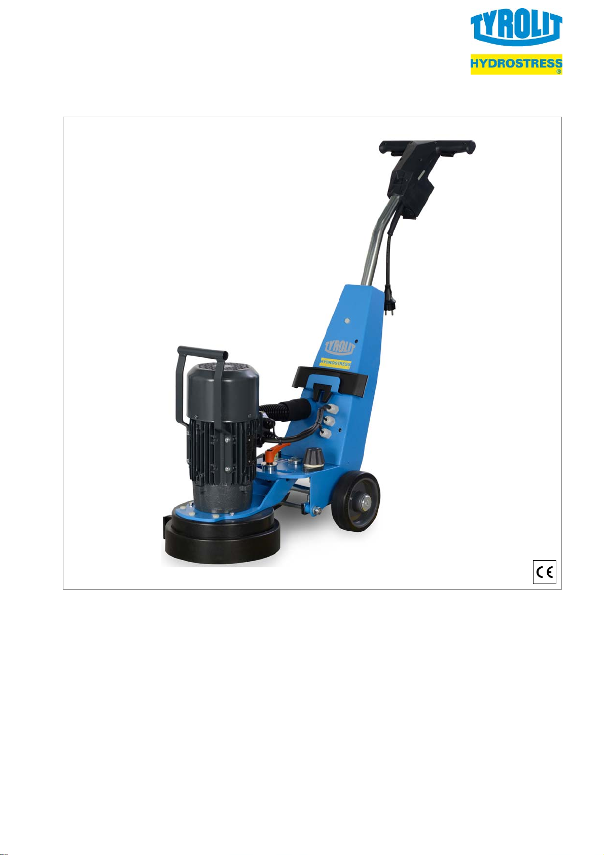
EN Floor grinding machine FGE 250
Translation of the original operating instructions 4...........................
1
Page 2

3
9
15
1
15
Fig. A
Fig. B
2
3
7
5
4
8
6
9
10
11
16
17
Fig. D
22
7
18
20
19
11
21
23
24
13 4 5
Fig. C
14
12
12
7
11
26
Fig. E
Fig. F
23
27
25
7
25
24
2
Page 3
23
Fig. G
Fig. J
Fig. H
Fig. J
23
27
24
25
14
26
28
Fig. K
2614
14
7
7
Fig. L
12
Fig. M
4
3
Page 4

EN Floor grinding machine FGE 250
Translation of the original operating instructions
Manufacturer: TYROLIT Hydrostress AG
Witzbergstrasse 18
CH-8330 Pfäffikon ZH
Telephone: +41 (0)44 952 18 18
Telefax: +41 (0)44 952 18 00
URL: www.tyrolit.com
Document: 10999135_en
Publishing date: 16.01.2018
Key to the illustrations
Pos. Fig. Designation
1 A Handle
2 A Safety switch
3 A/D Guide bar
4 B/C/M Drive (swivelling)
5 B/C Extraction hose
6 B Water level
7 B/C/
E/L
Cover
8 B/C/D Holder
9 B/D Machine console
10 B/M Carriage height adjustment
11 B/C/D Transport wheel
12 B Clamping screw for drive
13 C Transport grip
14 C/K/L Safety hood
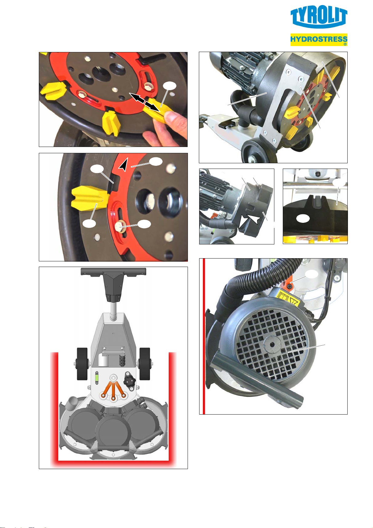
© TYROLIT Hydrostress AG
TYROLIT Hydrostress AG reserves all rights. Any
reproduction, use or distribution of these original ope
rating instructions or the translations of the original
operating instructions, in whole or in part, is prohi
bited without the express written permission of TY
ROLIT Hydrostress AG. If the product described here
is altered without the consent of the manufacturer,
then said manufacturer is not responsible for any
damage that may be incurred. Any such actions will
void the warranty.
Pos. Fig. Designation
15 D Clamping screw for guide bar
16 D Power plug
17 D Balancer
18 D Transport bar (optional)
19 D Connection for dust extraction
20 D Assembly tool
21 D Wheel axle
22 E Grinding plate
23 E/F/
G/H
24 E/F/H Clamping screw for retaining ring
25 E/F/H Retaining ring
26 E/K/L Suction ring
27 F/H Recess for tool change
28 K Slide plate
ETX diamond tool
Contents
1 Important notes 5..........................
1.1 Symbols used 5........................
1.2 Liability and warranty 5..................
2 Safety 5...................................
2.1 Accident prevention and safety 5.........
2.2 Safety instructions 6....................
3 Operation 7................................
3.1Startingupthemachine 7...............
3.2 Grinding 8.............................
3.3 Switching the machine off 8..............
4 Troubleshooting 9..........................
4
5 Maintenance 9.............................
5.1 Customer service and spare parts 9.......
5.2 Mounting and dismantling ETX diamond tools 9
5.3 Cleaning the machine 10.................
5.4 Checking electrical components 10........
5.5 Final tasks 10...........................
6 Acceptance and transport 10..................
6.1 Accepting the machine 10................
6.2 Transporting the machine 10..............
7 Technical data 11...........................
8 Declaration of conformity 11..................
Page 5
EN Floor grinding machine FGE 250
1 Important notes
1 Important notes
The machine may be used only with the accessories
supplied by the manufacturer for stripping, wet and
dry grinding of floor surfaces such as:
— cement
— screeds
— synthetic resin screeds / asphalt
— natural stone floors
— residual adhesive or filling compound
— floor remnants (e.g. foam backing)
Any other use of the machine can lead to dangerous
situations and is prohibited!
To ensure correct use of the machine, follow the in
structions in the operating instructions, paying parti
cular attention to any warnings and instructions re
lating to operation and maintenance!
Before using the machine, the opera
ting personnel must carefully read and
understand these operating instruc
tions!
Keep these operating instructions
close at hand for easy reference!
Read and observe documents and operating instruc
tions provided by suppliers!
1.2 Liability and warranty
TYROLIT Hydrostress AG
All rights, including those pertaining to translation, lie
with TYROLIT Hydrostress AG.
No part of this documentation may be reproduced,
used or distributed in any form without the written
permission of TYROLIT Hydrostress AG.
Liability or warranty is excluded if:
— The instructions in the operating instructions have
not been observed.
— The machine or its attachments were improperly
operated.
— The maintenance was carried out inadequately or
incorrectly.
— Specified spare parts were not used.
— The protective equipment was not used, has been
altered or was removed.
— The specified power supply ratings and surroun
ding conditions have not been observed.
The manufacturer is not liable for any damage that
may result if the user makes any changes to the ma
chine without the manufacturer’s permission. Any
such actions will void the warranty.
If the machine is on loan to other parties, the opera
ting instructions needs to be provided with the ma
chine and its importance must be made clear!
1.1 Symbols used
The following symbols are used in this
documentation:
Safety instructions
This symbol indicates warnings, prohibitions and
instructions regarding potential hazards. These
instructions must be obeyed and closely
observed.
Some safety instructions are accompanied by
corresponding symbols.
Warning Prohibition
Additional information
This symbol indicates additional information.
Direction
2 Safety
This chapter contains a summary of the most import
ant information on safety when handling the machine.
2.1 Accident prevention and safety
The following instructions comply with legislation, di
rectives and publications such as:
— EU Machinery Directive
— EU Product Liability Directive
— Law governing technical materials
— Law governing equipment safety
— Law governing product liability
These operating instructions are intended for opera
tors and tool setters, as well as for the personnel that
service, maintain and repair the machine. Together
with all the technical documentation, it is intended to
help
— avoid hazardous situations
— use the machine for its intended applications
— avoid downtime and repair costs
— maintain the function of the machine
— extend the service life of the machine.
5
Page 6

EN Floor grinding machine FGE 250
2 Safety
The manufacturer and owner of the machine must
observe the contents and provisions of the EC direc
tives. The effectiveness of any measure ultimately
depends on how well all parties, i.e. the manufac
turer, the owner and the machine operators, work
together to uphold safety standards.
All laws and regulations (e.g. the valid regulations on
waste disposal), accident prevention guidelines and
generally recognised safety rules must be complied
with when working on and with the machine!
2.2 Safety instructions
This machine incorporates state of the art technology
and has been built in accordance with recognised
safety regulations. This ensures that the highest pos
sible standards of occupational safety are main
tained. However, incorrect use of the machine could
endanger the health and lives of the personnel or
cause material damage.
The machine may only be operated by people
who have been assigned to do so and who have
the appropriate training and skills!
If any defects are found in the machine that
could endanger people or damage property,
stop the machine immediately and ensure that it
cannot be used again until all repairs have been
completed!
The operating and maintenance personnel resp
onsible for the machine must ensure that no one
can enter the machine’s danger zone during
operation or maintenance work!
Risk of injury from rotating machine parts!
Limbs and clothing can be drawn in!
Proceed with the greatest care and caution!
When working on the machine (setup, mainte
nance, service, repair, cleaning, etc.), the power
supply of the machine has to be disconnected
from the mains (pull plug).
High-voltage electrical current can be fatal!
Only connect the machine to power supplies
equipped with a ground fault circuit interrupter!.
Connections with mains cables
must be protected from splash water!
Only suitably knowledgeable, qualified profes
sional electricians may perform work on any
electrical parts of the system!
Risk of poisoning due to harmful substances at
the workplace!
Eating, drinking and smoking at the workplace is
not permitted. Always eat in break rooms or
canteen areas!
After completing the work, thoroughly clean
yourself!
A general inspection of the machine must be
conducted before starting up the machine! Parti
cular attention should be paid to damaged or
loose components, and wear!
Risk of injury if safety equipment has been
removed or is non-functional!
The safety equipment must be checked for com
pleteness and function before start-up!
The safety equipment must be in place during
operation!
The surfaces to be ground by the machine must
be free of obstacles.
6
The machine may only be put into operation if it
is in perfect technical condition!
Adding to or modifying the machine in any way
that could compromise operating safety is prohi
bited!
Cleaning and maintenance may be done only by
trained personnel!
Maintenance must be conducted as described in
the operating instructions!
Do not use high pressure cleaners to clean the
machine!
Do not operate the machine in areas where
there is risk of explosion or where flammable
materials are present.
Page 7

EN Floor grinding machine FGE 250
3 Operation
3 Operation
Risk of injury from parts flung out during grin
ding!
Wear protective clothing and protective goggles!
Wear safety shoes!
Wear protective gloves!
Proceed with the greatest care and caution!
Danger of injury from loud noise during grinding
operation of the machine! Emission value is
greater than 85 dB (A).
Always wear hearing protection when the ma
chine is in operation!
Always use ETX diamond tools or abrasive bonding
for the surface to be machined (e.g. some surfaces
have to be ground wet).
1. Check the surface to be ground and remove any
protruding objects.
2. Loosen the clamping screw [15, Fig. D], adjust
the guide bar [3, Fig. D] to the appropriate work
position and retighten the clamping screw.
3. Check ETX diamond tools for function and con
dition and replace if necessary.
(! Chapter 5.2 ‐ page 9).
4. Place the grinding plate [22, Fig. E] with the in
serted ETX diamond tools [23, Fig. E] on the
surface to be ground.
5. Turn the carriage height adjustment [10, Fig. B]
until the machine is aligned horizontally ac
cording to the built-in water level [6, Fig. B].
6. either:
Prepare for standard floor grinding
(! Fig. K/L)
a. Push cover [7] onto the slide plate [28].
b. Turn suction ring [26] until the cover lat
ches into the safety hood [14, Fig. L left].
or:
Prepare for edge grinding
High-voltage electrical current can be fatal! Do
not allow the power line to be run over, crushed
or pulled on!
Risk of injury from dust formation during grin
ding work!
Connect an extractor unit to the machine or feed
in water during the grinding process.
Wear respiratory protection!
3.1Startingupthemachine
Observe the safety instructions in Chapter 2!
The initial start-up of the machine may be car
ried out only by qualified personnel!
A visual inspection of the machine needs to be
done before starting up the machine.
Particular attention should be paid to damaged
or loose components, wearing and filling levels.
(! Fig. B/C/K/L/M)
a. Pull cover [7] from the slide plate [28] and
insert into the holder [8].
b. Turn the suction ring [26] with the slide
plate [28] to the corresponding edge side
(right or left) (! Fig. J].
c. Loosen the clamping screw [12] by hand.
d. Swivel the drive all the way to the appro
priate side (right or left) (! Fig. J/M].
e. Tighten clamping screw.
f. Align slide plate [28] to the wall (! Fig. J/M
help lines).
7. Attach external dust extraction (customer side)
at the connection to the dust extraction
[19, Fig. D].
8. Check the safety equipment for completeness
and function before starting up!
Risk of damage due to tensile strain exerted by
the power line!
9. Connect the line for the power supply of the ma
chine with the balancer [17, Fig. D].
7
Page 8

EN Floor grinding machine FGE 250
3 Operation
The power socket serving as the electric supply
should be installed and provided with mains cur
rent according to local regulations!
Risk of injury from inadvertent starting of the
machine!
Before plugging in the power plug, make sure
that the safety switch on the machine is swit
ched off, i.e. not pressed in.
10. Plug power plug [16, Fig. D] into the socket (use
extension cable if necessary).
The machine is ready for operation.
3.2 Grinding
Risk of damage and injury from uncontrolled
movement of the machine!
Before pressing the safety switch, the machine
has to be held firmly by the handle of the guide
bar.
11. If necessary, feed in water onto surfaces that
are to be ground wet.
12. Hold the machine by the handle [1, Fig. A] of the
guide bar.
3.3 Switching the machine off
Observe the safety instructions in Chapter 2!
Risk of injury from grinding plate still rotating
after the machine is switched off!
Only switch off the machine with the ETX dia
mond tools resting on the floor.
The grinding plate can otherwise still rotate idly
(run-on) for several seconds after being swit
ched off or the safety switch is released.
— Release safety switch [2, Fig. A] on both sides.
The machine is switched off.
Risk of injury from high voltage!
When the safety switch is released, the machine
still has voltage.
To de-energize the machine, pull the power plug
from the line to the voltage supply.
13. Press the safety switch [2, Fig. A] on one or
both sides and hold tight.
The surface to be ground can now be machined.
Depending on the application, the machine
needs to be retrofitted (! Pos. 7).
8
Page 9

EN Floor grinding machine FGE 250
4 Troubleshooting
4 Troubleshooting
Only suitably knowledgeable, qualified profes
sional technicians may perform repairs on the
machine.
Malfunction
Machine will not start. Connecting cable for the voltage sup
Grinding pattern is uneven. ETX diamond tools are loose. Fasten ETX diamond tools.
5 Maintenance
Cause Rectification
Plug power plug [16, Fig. D] into the
ply is not properly connected with the
power socket.
Connecting cable is defective. Replace connecting cable.
Safety switch is defective. Replace safety switch.
ETX diamond tools are damaged or
worn.
socket.
Replace ETX diamond tools.
5.2 Mounting and dismantling ETX diamond
tools
Observe the safety instructions in Chapter 2!
The operating and maintenance personnel resp
onsible for the machine must ensure that no one
can enter the machine’s danger zone during
operation or maintenance work!
Maintenance work may only be performed by
trained specialists! They must be familiar with
the dangers associated with such work, protect
themselves and avoid danger!
When working on the machine (set-up, mainte
nance, service, repair, cleaning, etc.), the power
supply of the machine has to be disconnected
from the mains
(disconnect power plug)!
Perform cleaning and maintenance work in ac
cordance with the operating manual and check
the safety equipment for completeness and
functionality.
5.1 Customer service and spare parts
In case of customer service queries, replacement
parts or repairs, please contact the manufacturer. To
ensure your queries are dealt with as quickly as pos
sible, always quote your machine data. These are
located on the machine’s nameplate.
The consistency of the surface to be ground de
termines type or the composition of the ETX diamond
tools to be used.
1. Pull the power plug [16, Fig. D] from the line to
the voltage supply.
2. Remove assembly tool [20, Fig. D] from the ma
chine console [9].
3. Place the machine with the handle [1, Fig. A] on
the floor (! Fig. K).
4. With the machine tipped, the grinding
plate [22, Fig. E] is accessible with the ETX
diamond tools [23, Fig. E].
The ETX diamond tools need to be checked for
wear and damage by the user before each use
and be replaced by new ones if necessary.
5. Use the assembly tool to loosen the three clam
ping screws [24, Fig. E] of the retaining ring.
6. Turn retaining ring [25, Fig. F] counter-clock
wise to full stop. (! arrow)
The three recesses [27, Fig. F] have to be posi
tioned each at one ETX diamond tool.
7. Loosen the ETX diamond tool [23, Fig. G] from
the grinding plate with a gentle strike of a lump
hammer and remove it. (! arrow)
8. Remove all ETX diamond tools.
9. Insert new ETX diamond tool [23, Fig. G] into
the recess [27, Fig. F] of the grinding plate and
press in firmly in the direction of the arrow (use
lump hammer if necessary).
10. Mount all ETX diamond tools.
11. Turn retaining ring [25, Fig. H] clockwise to full
stop. (! arrow)
9
Page 10

EN Floor grinding machine FGE 250
6 Acceptance and transport
12. Firmly screw in the three clamping
screws [24, Fig. H].
13. Set the machine upright.
14. Insert the assembly tool back into the machine
console [9, Fig. D].
5.3 Cleaning the machine
Observe the safety instructions in Chapter 2!
1. Pull the power plug [16, Fig. D] from the line to
the voltage supply.
2. Place the machine with the handle [1, Fig. A] on
the floor (! Fig. K).
3. Clean and dry the bottom side of the machine
and ETX diamond tools with a cloth or suitable
agents.
4. Set the machine upright.
5. Clean the machine dry with a cloth or suitable
agents.
5.4 Checking electrical components
6 Acceptance and transport
6.1 Accepting the machine
Observe the safety instructions in Chapter 2!
The machine is delivered in a complete and
packaged condition from the manufacturer.
1. Unpack machine and check the enclosed
delivery slip to make sure all parts are delivered.
2. Check whether any items have been damaged
in transit.
3. In case of damage, contact the transport com
pany immediately!
4. Report any problems to the manufacturer imme
diately!
Complaints at a later date cannot be acknowled
ged!
6.2 Transporting the machine
Observe the safety instructions in Chapter 2!
Only suitably knowledgeable, qualified profes
sional electricians may perform work on any
electrical parts of the machine!
Risk of fire due to faulty electrical cables!
— Check the mains cable and power plug regularly
for functional safety.
5.5 Final tasks
— Restart the machine if necessary
(! Chapter 3.1 ‐ page 7).
Risk of injury from heavy loads!
Suspended loads can fall or tip over, causing
serious injuries!
Do not stand under suspended loads!
Raising and lowering the load must be per
formed by two persons!
Do not raise loads any higher than necessary!
Prevent the load from swinging back and forth!
Keep sufficient safety distance!
Devices for transporting the unit have to be
rated to handle its full weight and dimensions.
Observe weight data on packaging or in the ac
companying documentation!
Never walk or reach beneath the load while it is
being lowered.
Wear safety shoes!
Wear protective gloves!
10
Proceed with the greatest care and caution!
For longer periods in transport or in storage, the
machine needs to be covered to protect it
against soiling.
Page 11

EN Floor grinding machine FGE 250
7 Technical data
The machine can be fastened to pallets to protect it
against damages. Relocation over short distances is
possible on the transport wheels.
1. Pull the power plug [16, Fig. D] from the power
outlet.
2. Fasten all loose parts to the machine.
3. either:
— Move the machine to the respective loca
tion with the transport wheels
[11, Fig. B/C/D] and deposit.
or:
a. Grab the machine by the handle [1, Fig. A]
and transport grip [13, Fig. C] and lift care
fully.
b. Lift the machine onto a suitable transport
device (e.g. a palette) and lower it.
c. Always secure the machine according to
regulations during transport by a vehicle or
suitable devices and strap down with
tension belts.
d. Move the machine to the respective loca
tion and deposit.
8 Declaration of conformity
TYROLIT Hydrostress AG
Witzbergstrasse 18
CH-8330 Pfäffikon ZH
Switzerland
We hereby declare that the machine
FGE 250
complies with the provisions described in
— Directive 2006/42/EG
Machine
— Directive 2014/30/EU
Electromagnetic Compatibility
The following harmonised standards apply:
— ISO 12100
Safety of Machinery
— EN 60204‐1
Electrical Equipment of Machines
— EN 61000-6-2/EN 61000-6-4
Electromagnetic Compatibility
This declaration is no longer valid if the machine is
modified or retrofitted without our prior consent and
approval.
7 Technical data
Designation FGE 250
Rated voltage 230 V, 1
Rated frequency 50 Hz
Rated current 13,2 A
Rated power 2,2 kW
Tool speed 1400 min
Protection rating IP 23
Dimensions
(LxBxH)
Working width () 250 mm
Grinding pressure 34 kg
Weight 54 kg
Noise level 79 dB(A)
Vibration total va
lue*)
*) Determined under standardised manufacturer ope
rating conditions according to the HARM measuring
method.
about 1000 x 400x 1000 mm
± 2,5 m/s
‐1
Pfäffikon, den 16.1.2018
Pascal Schmid
Entwicklungsleiter und Verantwortlicher für die
technischen Unterlagen
2
11
Page 12

TYROLIT Hydrostress AG
Witzbergstrasse 18
CH-8330 Pfäffikon ZH
Switzerland
Telefon: +41 (0)44 952 18 18
Telefax: +41 (0)44 952 18 00
URL: www.tyrolit.com
Page 13

1 Griff [1]
2 Sicherheitsschalter [2]
3 Führungsstange [3]
4 Antrieb [4] (rechts und links schwenkbar)
5 Schlauch [5]
6 Wasserwaage [6]
7 Abdeckung [7]
8 Halterung [8]
9 Maschinenkonsole [9]
10 Fahrwerk‐Höhenverstellung [10]
11 Transportrad [11]
12 Klemmschraube für schwenkbaren Antrieb [12]
13 Transportgriff [13]
14 Saugglocke [14]
15 Klemmschraube [15] für Führungsstange
16 Netzstecker [16]
17 Zugentlastung [17]
18 Transportstange [18] (Option)
19 Rohrstutzen [19]
20 Montagewerkzeug [20]
21 Radachse[21]
22 Werkzeugträger [22]
23 ETX-Diamantwerkzeuge [23]
24 Klemmschraube [24] für den Sicherungsring
TYROLIT Hydrostress AG
Witzbergstrasse 18
CH-8330 Pfäffikon ZH
Switzerland
Telefon: +41 (0)44 952 18 18
Telefax: +41 (0)44 952 18 00
URL: www.tyrolit.com
Page 14

25 Sicherungsring [25]
26 Abstandshaube [26]
27 Aussparung [27] Aussparung zum Werkzeugwechsel
28 Abstandblech [28]
AFig.A
BFig.B
CFig.C
DFig.D
EFig.E
FFig.F
GFig.G
HFig.H
I Fig. entfällt
JFig.J
KFig.K
LFig.L
MFig.M
TYROLIT Hydrostress AG
Witzbergstrasse 18
CH-8330 Pfäffikon ZH
Switzerland
Telefon: +41 (0)44 952 18 18
Telefax: +41 (0)44 952 18 00
URL: www.tyrolit.com
 Loading...