

Page 1
Owners Manual TYRO TRX2021
Rev. R1a
TYRO TRX2021
Remote control system
OWNERS MANUAL
Tyro BV, Bedrijvenpark Twente 1B, 7602 KA Almelo, Netherlands
Tel. +31 546 588790 Telefax +31 546 579490 [email protected]
1
Page 2

Owners Manual TYRO TRX2021
Rev. R1a
TABLE OF CONTENTS………………………………………………………………. 2-3
1. WARRANTY, LIABILITY, LAW
1.1. Important Notice………………………………………………………………….. 4
1.2 apprehension of the Manual..………………………………………………….. 4
1.3 liability……………………………………………………………………………… 4
1.4 age of use…………..……………………………………………………………… 4
1.5 law……….………………………………………………………………………….. 4
2. USE……………….…………………………………………………………………. 4
3. INTRODUCTION
3.1 risk…………………………………………………………………………………… 4
3.2 reliability…………………………………………………………………………….. 4
4. GENERAL
4.1 FM frequency and maximum distance of use………………………………… 5
4.2 interference of the signal.………………………………………………………… 5
4.3 Personal interpretation…………………………………………………………… 5
5. OPERATION
5.1 Switch delay………….…………………………………………………………….. 5
5.2 Power IN………………………………………………………………………….….. 5
5.3 E.L. Light……………………………………………………………………………. 5
5.4 Switch ON and OFF the E.L. Light……..………………………………………. 5-6
6. TECHNICAL SPECIFICATIONS
6.1 Use of the relays…………………………………………………………………... 6
6.2 user specifications….……………………………………………………………. 6
6.2.1 Receiver……….…………………………………………………… 6
6.2.2 Sender……………………………………………………………… 6
6.2.3 Reach………………………………………………………………. 6
6.3 control, master-slave….………………………………………………………… 6
6.4 Battery Pack……………………………………………………………………….. 6
7. ENVIRONMENTAL TESTS AND SPECIFICATIONS…………………………. 6
8. GENERAL RECOMMANDATIONS
8.1 risk………………..…………………………………………………………………. 7
8.2 Safety switch…...………………………………………………………………….. 7
8.3 recommended battery supply..…………………………………………………. 7
8.4 before starting…………….……………………………………………………….. 7
8.5 proportional speed………….…………………………………………………….. 7
Tyro BV, Bedrijvenpark Twente 1B, 7602 KA Almelo, Netherlands
Tel. +31 546 588790 Telefax +31 546 579490 [email protected]
2
Page 3

9 HOW TO PROGRAMME SENDER ON RECEIVER ………………………………. 7
9.1 Steps………………………………………………………………………………... 8
fig. 1 receiver print …………………………………………………………………… 8
10. EMERGENCY SWITCH AND END SWITCHES
fig. 2 picture receiver board…………………………………………………………. 9
10.1 Make- and break-contact……..……………………………………………….. 9
10.2 98/37/EC machinery directive..………………………………………………... 9
10.3 How to connect make and break contact……………………………………. 9
11. HOW TO CONNECT EMERGENCY SWITCH AND SAFETY SWITCH ON
THE PLC AND REMOTE CONTROL
Fig. 3 schematic drawing……………………………………………………………... 10
12. HOW TO CONNECT THE MAKE-CONTACT (default)
fig. 4 make-contact……………………………………………………………………. 11
12.1 system circuit……………………………………………………………………... 11
13. HOW TO CONNECT THE BREAK-CONTACT
(acc. To machinery directive 98/37/EC of June 22, 1998)
fig. 5 break-contact…………….……………………………………………………... 12
13.1 system-circuit……..……………………………………………………………... 12
14. WIRING THE RECEIVER
fig. 6 schematic terminal pressure..……………………………………………….. 13
fig. 7 Relay connections………….………………………………………………….. 13
DECLARATION OF CONFORMITY………………………………………………….. 14
3
Page 4
Owners Manual TYRO TRX2021
Rev. R1a
1. WARRANTY,LIABILITY, LAW
1.1. IMPORTANT NOTICE:
Everyone who gets involved with this
(wireless remote) control direct, through
mounting or through practical use, fully or
partial, is obliged to read and understand
this manual completely BEFORE
installation and/or use.
1.2 apprehension of the manual
When there is anything that you do not
understand and/or you need more clearness
or addition, you must contact your local
supplier or Tyro BV
1.3 liability
The manufacturer and/or the supplier of this
(wireless remote) control cannot be held
responsible and thus warranty and liability will
be voided, when, as a result of avoidable
errors because of taking uncareful notice, or
no notice at all, of the contents of this manual,
damage is caused to this product or other
products that are operated with this product or
on which this product is mounted, personal
injury explicit included.
1.4 age of use
The user of this product must be over 18 years
old or at least having reached the adult age
according to the law in the country of use or
having reached the age, that is demanded by
the law in the country of use.
1.5 law
This product is liable to the law in the country
of use. Before using this product every
supplier and/or every user is obliged to
investigate if the use of this product is
permitted under that law. Tyro BV cannot be
held responsible when the use is
not permitted, except for the original delivery
to her customer(s)
Tyro BV, Bedrijvenpark Twente 1B, 7602 KA Almelo, Netherlands
Tel. +31 546 588790 Telefax +31 546 579490 [email protected]
2. USE
This (wireless remote) control is meant to be
used to control machinery from a distance
within the legal guide-lines and is thus to be
considered as radio equipment as mentioned in
the 1999/5/EC directive of March 9, 1999, art. 2
par. c). The directives to which this (wireless
remote) control conforms and the tests to
which it is submitted, are mentioned in this
manual and/or in the added CE declaration of
conformity.
3. INTRODUCTION
3.1 risk
The product that you are going to use is
risk full with respect to the use. Before
switching ON the control, the user is
obliged to assure himself that these risks
cannot arise because of the use and to take
all necessary precautions to take away
these risks. BEFORE the user is switching
on the (wireless remote) control he has to
convince himself that he ALWAYS can keep
sight on the object that he is going to
control and to keep away any (non)experts
who find themselves in the danger zone and
thus could be injured,
3.2 reliability
To be certain that the (wireless remote) control
has a long and reliable duration of life, it is of
great importance that both the receiver and the
antenna are mounted in the correct way and
that both the transmitter and the receiver are
used correctly.
It may be obvious that the correct mounting
and the correct use will lead to a longer
duration of life and guarantee the best possible
reach.
4
Page 5

4. GENERAL
4.1 FM frequency and maximum distance
of use
The Tyro Systems (wireless remote) control
uses the 433.92 MHz frequency. The (wireless
remote) control is FM modulated and is thus
less accessible for interference of other
transmitting sources.
Besides this the Tyro Systems (wireless
remote) control is narrow banded, thus
reducing the interference as well. This allows
us to guarantee a 100% reach within a
distance of 50 meters (150 ft) under
´normal´conditions. (Interference of
environmental circumstances and more
powerful transmitting sources such as radio
installations emphatically excluded).
4.2 Interference of the signal
The operation of equipment that uses radiofrequency and wireless remote controls in
particular, are influenced by the power of the
received signal.
Because of the fact that the transmitting power on
the 433,92Mhz frequency (and comparable
frequencies), is reduced by law, the reach is thus
reduced. As applicable with powerful transmitting
sources (Radio-TV-, GSM-masts, atmospherics
etc.) under circumstances the reach could be
influenced by causes from the outside.
Because the transmitting power of this product is,
by law, reduced to max. 10 mW, the reach is also
reduced and the influence of transmitting sources
with more power (e.g. Radio-, TV-, GSM-masts) is
possibly getting bigger.
In spite of using the possibilities of GSM
Technology, it is impossible to 100% prevent
against influences from the outside.
However, by using PLC technique (Programmable
Logic Control) we have a better control over the
results of these influences, thus trying to prevent
from accidents by timely interference of the PLC or
taking over certain human actions.
4.3 Personal interpretation
At all times, however, you have to bear in mind
that circumstances could arise, where your
personal interpretation is of greatest
importance using safely with this product.
5. OPERATION
5.1 Switch delay
To switch ON the system, there is a delay of
±1 sec. This is done to let the user be aware
that he activates the system.
5.2 Power IN
When the start button is pressed (the green
button on the left bottom of the foil) In the
display (if applicable) the text “press ON and
wait” appears. If no display on the green button
the LED will light up. After pressing the button
±1 sec. and releasing again, in the display the
text “system active” appears, or the LED on
the green button lights permanently. The
control is now ready for use.
(Attention: when the button is released before
the switch delay is over, the system will not
become active.)
5.3 E.L. Light
The foil is foreseen with E.L. backlight,
helping to improve the good use under
difficult circumstances with bad (day) light.
This E.L. light, however, is using current,
diminishing the use of the battery of the
transmitter with approx. 65% reduced (from
±20 hrs to approx ±7 hour).
We strongly advise to use the E.L. backlight
only when there is reason to.
5.4 Switch ON and OFF the E.L. Light
The backlight could be switched OFF as
follows:
- Press the upper side of the both function
buttons at the same time
- Press de red button “O” for ± 0,5 sec. On
the display the text “backlight OFF”
appears.
5
Page 6

When the backlight is set to OFF, both the
light of the foil and the display are in OFF
mode.
Mode 2
The “master” mode can only be set in “slave” by
pressing the green button on the transmitter except
when one or more of the buttons on the receiver
are used..
To switch the backlight ON again:
- Press the upper side of the both function
buttons at the same time
- Press de red button “O” for ± 0,5 sec. On
the display the text “backlight ON” appears.
6. TECHNICAL SPECIFICATIONS :
IMPORTANT:
The transmitter has a 1500mAh. NiMh.
battery pack. In case it has to be replaced
this battery has to be treated as “KCA”
waste.
7. ENVIRONMENTAL TESTS AND
6.1 Use of the switch relays
The switch relays in the receiver can be used
constantly.
6.2 User specifications
6.2.1 Receiver:
Voltage 12-24Vdc
Max. Voltage 34Vdc
Max. contact load 3Amp (at 24Vdc)
Max. contact load 50Vdc
6.2.2 Transmitter:
Max. charging voltage 26Vdc
Min. charging voltage 14Vdc
standby time battery ± 150-200 hrs
Max. use battery ± 7 hrs (with E.L. light)
± 20 hrs (without E.L. light)
charging time to full ± 2 hrs
6.2.3 Reach:
Max. transmission 50 meters, 100% signal (under
“normal” circumstances)
6.3 Control Master-Slave
The receiver has 2 modes (only with extra foil on
the receiver).
Mode 1 “master mode“
Mode 2 “slave mode“
Mode 1
When pressing the “ON” button on the receiver the
red LED is flashing. This means that the buttons on
the receiver are “master”. In “master” mode the
system can only be used with the buttons on the
receiver.
Vibration MIL-STD 810F. Basic Transportation
Shock acc IEC 68-2-27, halfsinusform pulse,
Bump acc IEC 68-2-29, acceleration 25g
Dry heat acc IEC 68-2-2 test Bd, temp. +85C
Cold acc IEC 68-3-1, operational temp. –
Humidity acc IEC 69-2-30 test Db, cycles betw.
Salt mist acc IEC 68-2-11 test Ka
EMC
CE-dir. (R&TTE) directive 1999/5/EC E-dir. (VD)
Automotive of Vehicle Directive 95/54/EC
EN 61000-4-2 ESD, contact and air discharge up to
15 kV
ISO 11542-1 radiated immunity, 10 kHz – 18 GHz,
am-modulated, horizontal and vertical polarization,
dwell-time 1s, field 100 V/m
ISO 11542-4 conducted immunity, Bulk current
injection, frequency range 1 MHz – 400 MHz, ammodulated, dwell time 2s, injection volt. 100 mA.
ISO 11452-7 Direct RF-injection, frequency range
0,25 MHz – 400 MHZ, am modulated, dwell time
2s, injection capacity 0,5 W
ISO 7637-0 conduction, transients
ISO 7637-1 electrical transient conduction along
supply lines only, 12 V systems (to ensure proper
vehicle operation, onboard testing is essential)
ISO 7637-2 electrical transient conduction along
supply lines only, 24 V systems (to ensure proper
vehicle operation, onboard testing is essential)
EN 55011 radiated emission, frequency range 30
MHz – 1 GHz via antenna
6.4 Battery Pack
SPECIFICATIONS
acc 514.5C-1 (highway truck vibration
exposure). Freq. Range: 5-500Hz
acceleration 50g
30C, storage –40C
25D en 55C, rel. humidity >90%
:
6
Page 7

8. GENERAL RECOMMANDATIONS
8.1 risk
By meaning of operation the use of wireless
remote controls can lead to injury or damage
to property, direct or indirect, if used
injudicious.
To limit those risks and/or to prevent against,
one is obliged to take following precautions:
8.2 Safety switch
ALWAYS mount a safety switch in the system
and use it accordingly, in order to be able to
switch off the main power supply to the
equipment. This safety switch must have a
button that can be pressed when necessary,
thus cutting off the power supply. Safety
switches and other safety devices need to be
maintained preventive at least every month.
Grease or spray the terminals with an anticorrosion product.
When a wireless remote safety switch is used,
it has to be checked on proper operation as
often as necessary or at least once every
month.
8.3 recommended battery supply
Check the battery supply frequently. The
battery supply to use this (wireless remote)
control may not be less than 10V DC.This
(wireless remote) control may not be used
below these values as damage may occur. Is
this (wireless remote) control used below
these values anyhow, the proper operation
cannot be guaranteed. The manufacturer
cannot be held responsible for injury and/or
damage that is the result of this.
8.4 before staring
Before switching the safety switch to ON and
before switching the (wireless remote) control
to ON, the user must be certain that no risks
(can) arise by the use and has to take all
necessary precautions to prevent against
those risks.
BEFORE switching ON the control ALWAYS
keep sight on the equipment that is to be
moved and keep all (non) experts away who
are in close vicinity and thus can be in danger,.
Switch ON the safety switch.
Next press the green button on the (wireless
remote) control for ± 0,5 sec.
The system is active for use (the LED lights
constantly)
8.5 proportional speed
The whole surface of the buttons can be used
to move the equipment.
However, the buttons are foreseen with
proportional speed. By sliding over the foil with
your finger, the speed of the equipment will
change, all to the possibilities.
To be able to use proportional speed the PLC
needs to be foreseen with an analog part (this
is an option)
.
Besides this the equipment also needs to be
suitable for proportional speed.
A winch that uses solenoids (ON-OFF switch) does
not have this possibility. When the winch is
equipped with a so called motor control, thus
controlling the power supply electronically,
proportional speed can be used (ask your supplier).
Hydraulic winches that are foreseen with an
electric-proportional valve already can use this
proportional speed control.
9. HOW TO PROGRAMME SENDER
ON RECEIVER
To be able to start data transmission between
transmitter and receiver, they have to be
programmed.
In general this is done in the factory. However,
when this is not the fact, or when, for one or
another reason, the data transmission does not
work, you may follow the steps under 9.1.
7
Page 8
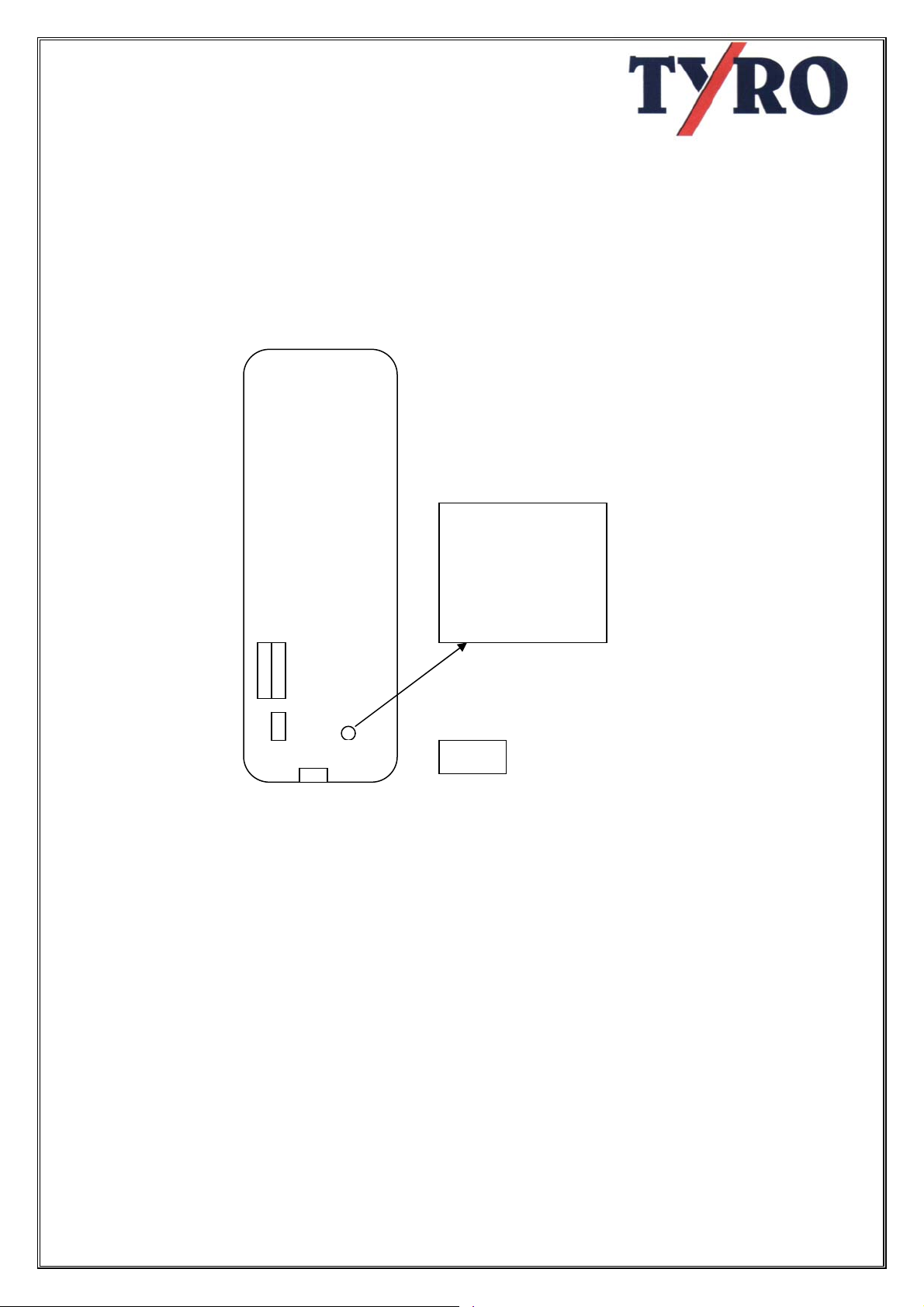
9.1 Steps
- Cut off the systems power supply.
- On the receiver board, right below
the PLC, you will see a button with
the text “ADR”,
Print Board
receiver
(this board
is located
below the
PLC )
ADR
- Press
- Switch on the power supply.
- Press the green button on the
transmitter and keep it pressed.
- As soon as the start relay on the PLC
switches, loosen the start button
- The system is now ready for use.
Press ADR button
followed by the start
button on the
transmitter unit the
relay on the PLC
switches.
Fig.1
8
Page 9
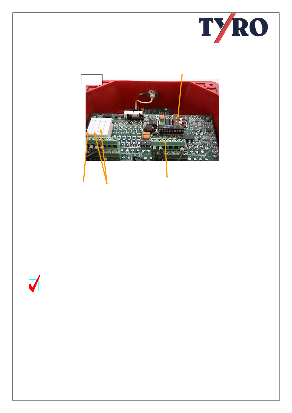
10. Emergency Switches and End Switches
Fig. 3
Fig.2
Start relay
functionrelay
10.1 make - and break-contact
The PLC is foreseen with the possibility of
connecting emergency switches as well
as end switches. These can be
connected as make- or as break contact.
To switch between these contacts the
dip-switches on the PLC board need to
be set.
10.2 Directive 98/37/EC
Attention:
Following the Machinery directive
98/37/EC of June 22, 1998, you are
obliged to mount this control according
to the description of the break-contact.
The settings of the make-contact is
default "OFF" from the factory in order to
be able to test the control without
complete installation
10.3 how to connect make- or break
contact
The make- or break contact can be set by
using the dipswitches (fig. 3).
Dipswitch 1, 2 en 3 are corresponding with the
inputs i1, i2 en i3.
Every input can be set individually.
If the dipswitch is set on “OFF” the
corresponding input is in make-contact mode.
If the dipswitch is set on “ON” the
corresponding input is in break-contact mode.
dipswitch
Inputs
9
Page 10
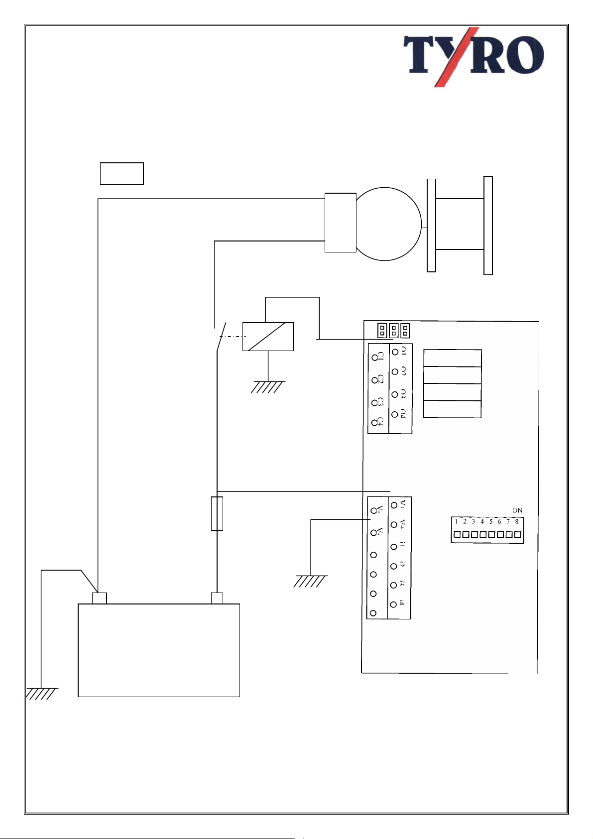
11. HOW TO CONNECT EMERGENCY SWITCH AND SAFETY
SWITCH ON THE PLC AND REMOTE CONTROL
-
Fig.3
Motor
Fuse
+
Battery
10
Page 11
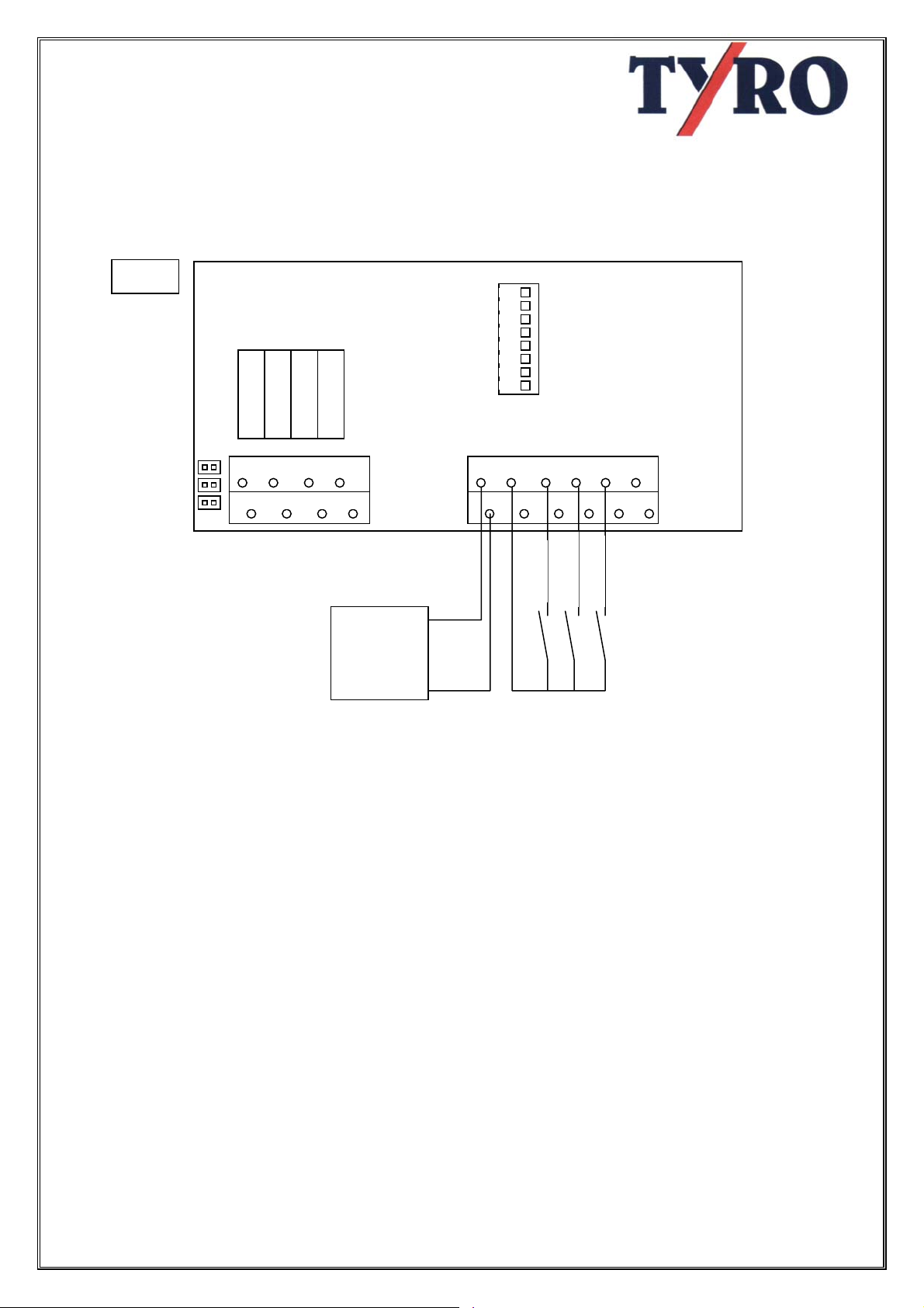
11. HOW TO CONNECT THE MAKE-CONTACT (DEFAULT)
Normally Dipswitches are set on "ON"
Fig.4
JMP3
JMP2
C1 C2 C3 C4
Battery +
-
11.1 system circuit
When the make-contact is set on "ON"
the system works as follows:
If voltage is on “i1” (emergency stop) all
relays (outputs "Q") are cut out
immediately.
If NO voltage is on “i1” (emergency stop)
the system is active
If voltage is on “i2” (End switch 1), “Q2”
(function) is cut out immediately.
8 7 6 5 4 3 2 1
ON
+
+
V- V-JMP1
Emergenc
Endswitch 2
Endswitch 1
If NO voltage is on “i2” (End switch 1),
“Q2” (function outputs "Q2" en "C2") is
active (e.g. winch IN)
If voltage is on “i3” (End switch 2), “Q3”
(function) is cut out immediately.
If NO voltage is on “i3” (End switch 2),
“Q3” (function outputs "Q3" en "C3") is
active (e.g. winch OUT)
11
Page 12
Ei d t d 1
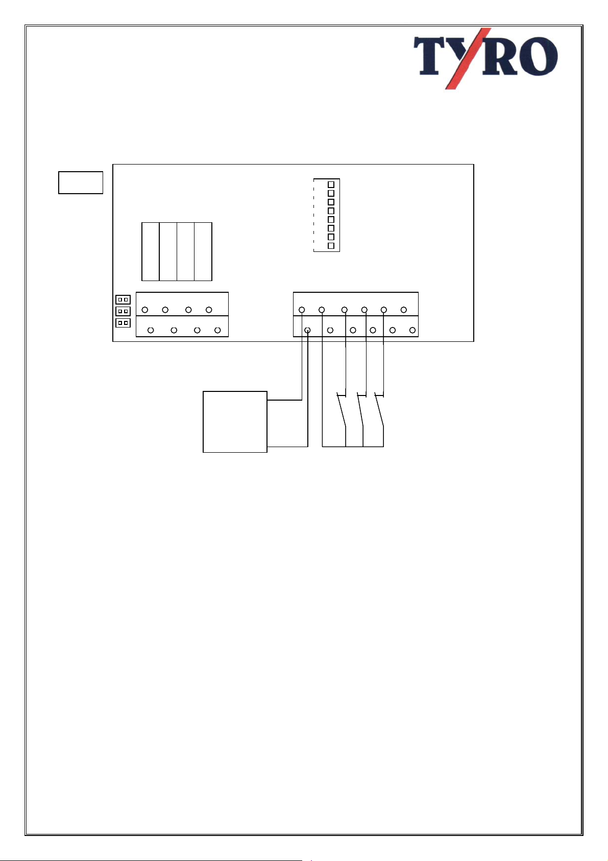
12. HOW TO CONNECT THE BREAK CONTACT
(according to the Machinery directive 98/37/EC of June 22, 1998)
Fig.5
JMP3
JMP2
JMP1
C1 C2 C3 C4
Battery +
-
12.1 system circuit
When the break-contact is set on "OFF"
the system works as follows:
If NO voltage is on “i1” (emergency stop)
all relays (outputs "Q") are cut out
immediately.
If voltage is on “i1” (emergency stop) the
system is active
If NO voltage is on “i2” (End switch 1),
“Q2” (function) is cut out immediately.
If voltage is on “i2” (End switch 1), “Q2”
(function outputs "Q2" en "C2") is active
(e.g. winch IN)
ON
1 2 3 4 5 6 7 8
+
+
V- V-
Emergenc
Endswitch 2
Endswitch 1
If NO voltage is on “i3” (End switch 2),
“Q3” (function) is cut out immediately.
If voltage is on “i3” (End switch 2), “Q3”
(function outputs "Q3" en "C3") is active
(e.g. winch OUT)
12
Page 13
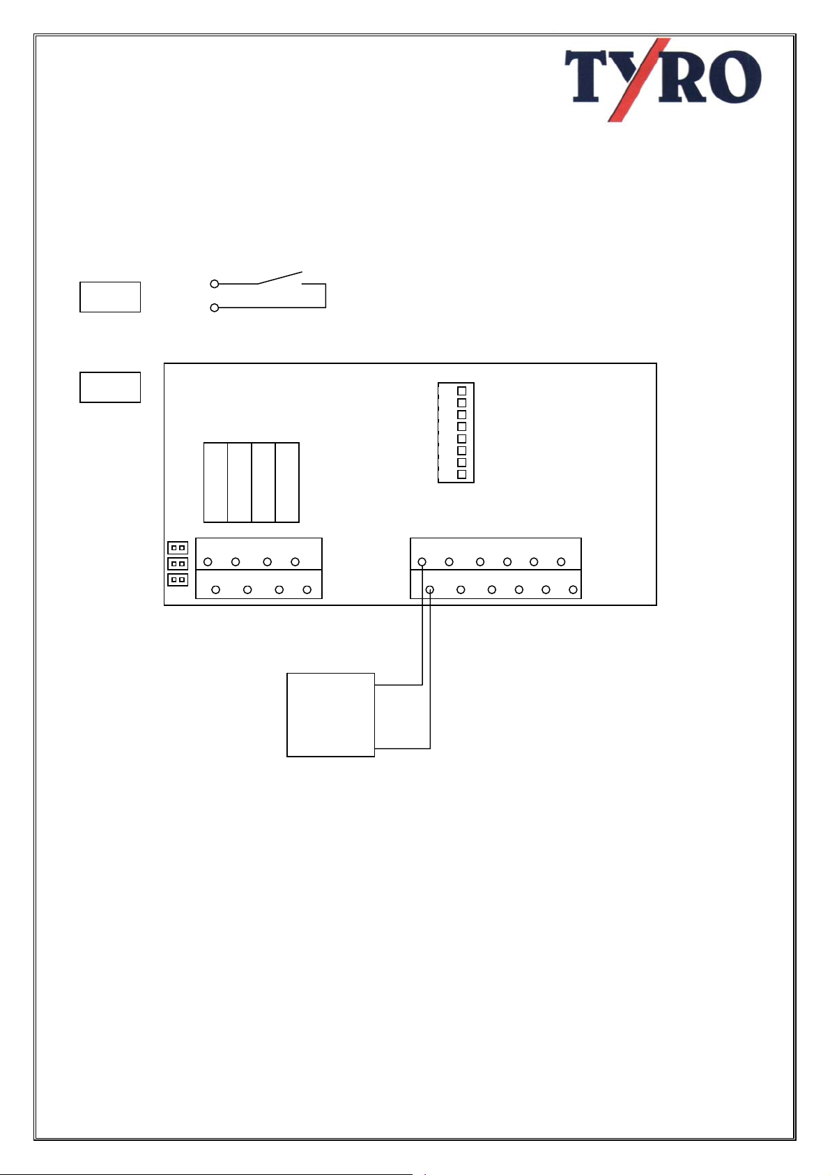
13. WIRING THE RECEIVER
How to wire the relays.
The relay contacts are connected to the board as follows:
Fig.6
Fig.7
JMP3
JMP2
JMP1
Q1 = system active
Also a solenoid can be switched that is
used as emergency cut out for the whole
system.
Q2 = function 1 (winch "IN") (Up)
Q3 = function 2 (winch "OUT") (Down)
Cn
Qn
C1 C2 C3 C4
Battery +
-
ON
1 2 3 4 5 6 7 8
+
+
V- V-
Default function C1, C2 and C3 are
connected to V+ through Jumper JMP1,
JMP2 en JMP3. The advantage is that
no wiring is needed.
13
Page 14
CE Declaration of Conformity
following directive 1999/5/EC of March 9, 1999
and their consequences (mem (10) and (11))
following directive 73/23/EC of february 19, 1973,
following directive
and following the EMC Directive 89/336/EC of may 3, 1989 (95/54/EC),
both modified by directive 93/68/EEC of august 30, 1993
Bedrijvenpark Twente 1b, 7602 KA Almelo
Declare in solemn responsibility,
WIRELESS REMOTECONTROL TY-TRX2021
On which this declaration is based,
Conforms to the health and safety demands of EC directive 89/336/EC (95/54/EC),
and the demands of the conforming directive 73/23/EC, both modified by directive
93/68/EC of August 30, 1993
For a correct use of the health and safety demands in these directives following
norms and/or technical specifications were used
98/37/EC of June 22, 1998
We, TYRO BV,
that the product
Manufactured by
TYRO BV
ETS 300220
ETS 300683
Wijk bij Duurstede 20-02-2001 Herman Albers Spierings
Managing director
14
 Loading...