

Page 1

Oper
ating Instructions
Instrucciones de Oper
Mode d’Emploi
acion
2
3
*Schematic Drawings Inside
Warnings for the safe use of this tool are included in this manual.
Los avisos para el uso seguro de esta herramienta están incluidos
en este manual.
Les consignes pour l’utilisation en toute sécurité de cet outil se
trouvent dans ce manuel.
Questions? Comments? Contact: 1.800.396.3318
or visit our website: www.rextool.com
© 2007 by Rex Commercial Tools and Fasteners, LLC
OMU008 Revised December 11, 2007
Rex Commercial Tools and Fasteners, LLC
754 Cincinnati Batavia Pike
Cincinnati, Ohio 45245
Page 2
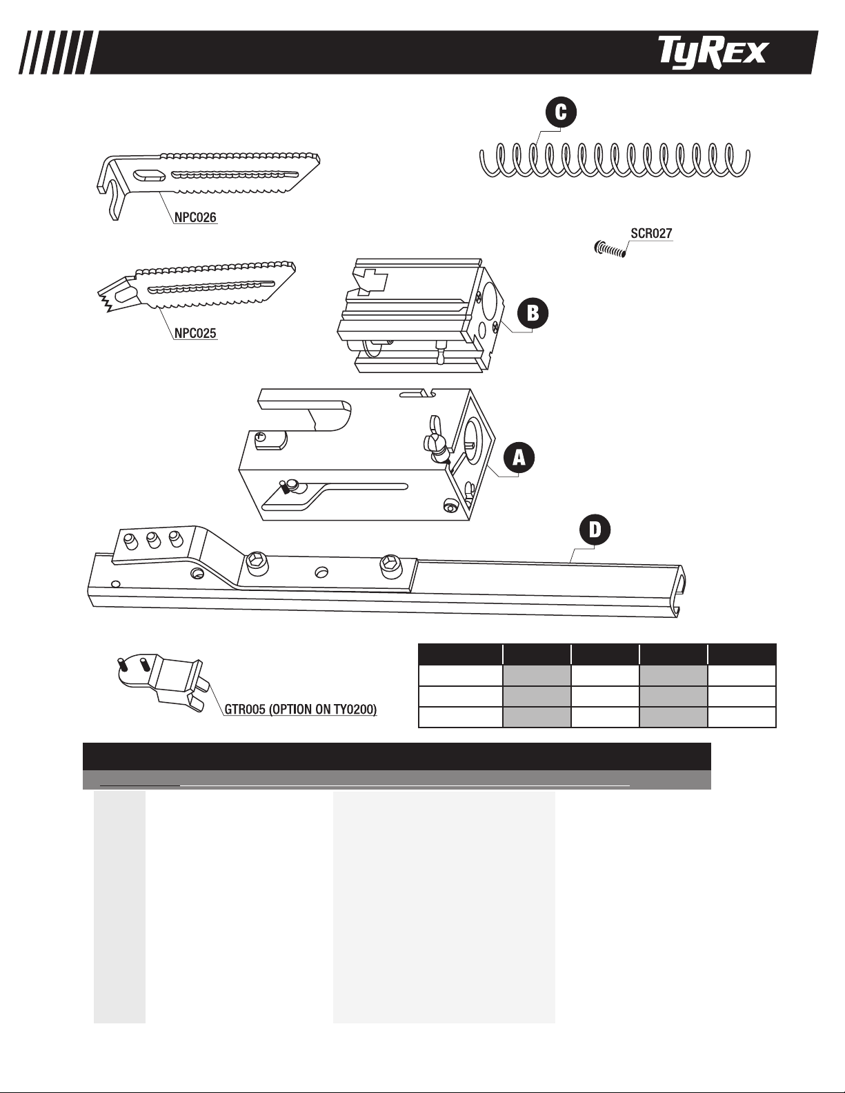
TY0100, TY0200, TY0300
TM
TOOL MODEL A B C D
TY0100 TBA003 SBA006 SPR021 GTR007
TY0200 TBA004 SBA007 SPR021 GTR007
TY0300 TBA005 SBA008 SPR022 GTR006
REPLACEMENT PARTS LIST•LISTA DE PARTES DE REPUESTO•LISTE DE PIÈCES DE RECHANGE
PART NO. DESCRIPTION DESCRIPCIÓN DÉSIGNATION
GTR005 ...........FEED CLIP ............................... GUÍA DEL TORNILLO .................................GUIDE DE VIS
GTR006 ...........GUIDE RAIL ............................. CARRIL DE GUÍA .......................................VOIE DE GUIDE
GTR007 ...........GUIDE RAIL ............................. CARRIL DE GUÍA .......................................VOIE DE GUIDE
NPC025 ...........TOE NAIL NOSEPIECE .............. PIEZA DE LA BOCA ...................................EMBOUT
NPC026 ...........FLUSH NOSEPIECE .................. PIEZA DE LA BOCA ..................................EMBOUT
SBA006 ...........SLIDE BODY ASSEMBLY .......... CONJUNTO DE CUERPO DESLIZANTE .......ASSEMBLAGE BLOC GLISSIERE
SBA007 ...........SLIDE BODY ASSEMBLY .......... CONJUNTO DE CUERPO DESLIZANTE ......ASSEMBLAGE BLOC GLISSIERE
SBA008 ...........SLIDE BODY ASSEMBLY .......... CONJUNTO DE CUERPO DESLIZANTE .......ASSEMBLAGE BLOC GLISSIERE
SCR027 ...........NOSEPIECE SCREW................. TORNILLO PARA PIEZA DE LA BOCA .........VIS POUR EMBOUT
SPR021 ...........FEED SPRING .......................... MUELLE ....................................................RESSORT
SPR022 ...........FEED SPRING .......................... MUELLE ....................................................RESSORT
TBA003 ...........FEED TUBE ASSEMBLY ............ CONJUNTO DE TUBO
TBA004 ...........FEED TUBE ASSEMBLY ............ CONJUNTO DE TUBO ................................
TBA005 ...........FEED TUBE ASSEMBLY ............ CONJUNTO DE TUBO ................................
...................................ASSEMBLAGE TUBES
ASSEMBLAGE TUBES
ASSEMBLAGE TUBES
2
Page 3

General Safety Rules
DS200-D2
DS200-D4
Warnings for the safe use of this tool are included in this manual.
Los avisos para el uso seguro de esta herramienta están incluidos
en este manual.
Les consignes pour l’utilisation en toute sécurité de cet outil se
trouvent dans ce manuel.
Operating Instructions
Instrucciones de Operacion
Mode d’Emploi
?????
D600-2
D600-4
D600ATT
*S
c
hematic D
r
awings Inside
© 2007 by Rex Com
mercial Tools and Fasteners, LLC
Questions? Comments? Conta
ct: 1.800.396.3318
or visit our website: www
.tyrextools.com
Rex Commercial Tools and Fasteners, LLC
754 Cincinnati Batavia Pike
Cincinnati
,
Ohio 45245
Authorized
Service Center
S a f e t y Warnings Avisos de Seguridad Consignes de Sécurité
English Espanol Francais
Read and understand all
Warning!
instructions. Failure to follow
all instructions listed below,
may result in electric shock, re
and/or serious personal injury.
SAVE THESE
INSTRUCTIONS
Keep bystanders, minors, and
visitors away while operating a
power tool. Distractions can
cause you to lose control.
Personal Safety
Stay alert, watch what you are do-
ing, and use common sense when
operating a power tool. Do not
use tool while tired or under the
influence of drugs, alcohol, or medication. A moment of inattention
while operating power tools
may result in serious personal
injury.
Do not overreach. Keep
proper footing and balance
at all times. Proper footing
and balance enable better
control of the tool in unexpected situations.
Advertencia!
Lea y comprenda todas las
instrucciones. La falta de ob-
servación de todas las instrucciones listadas a continuación
puede causar choque eléctrico,
incendios o lesiones graves.
GUARDE ESTAS
INSTRUCCIONES
Mantenga s los acompañantes,
menores y visitas alsjados mientras usted utiliza la herramienta
de motor. Las distracciones
pueden hacer que usted
pierda el control.
Seguridad personal
Cuando utilice una herramienta de
motor, manténgase a;erta, preste
atención a lo que está haciendo y
aplique el sentido común. No use
la herramienta cuando se sienta
cansado o se encuentre bajo los
efectos de drogas, alchol o medicamentos. Un momento de falta
de atención mientras utiliza una
herramienta de motor puede
ocasionar lesiones graves.
No se estire para trabajar.
Mantenga en todo momento
una posición adecuada y
el equilibrio. La posición y
el equilibrio adecuados le
permiten contrilar mejor la
herramienta ante situaciones
inesperadas.
Avertissement !
Maintenez votre zone de
travail propre et bien éclairée. Des établis en désordre
et des zones mal éclairées
augmentent les risques
d’accident.
CONSERVEZ CES
INSTRUCTIONS
Maintenez les spectateurs,
enfants et visiteurs à l’écart
lorsque vous utilisez de
l’outillage électrique. Toute
distraction risque de vous
faire perdre le contrôle de
votre outil.
Sécurité corporelle
Soyez en bonne condition phy-
sique, soyez attentif à ce que vous
faites et faites preuve de bon sens
lorsque vous utilisez un outillage
électrique. N’utilisez pas votre
outil si vous êtes fatigué ou sous
l’influence de drogues, alcool
ou médicaments. Un moment
d’inattention lors de l’utilisation
d’un outillage électrique peut
être la cause de graves blessures corporelles.
Ne présumez pas de vos
forces. Restez bien stable et
en équilibre à tout moment.
Une position stable et bien
équilibrée vous permettra de
mieux réagir à une situation
inattendue.
Use safety equipment.
Always wear eye protection. Dust mask, non-skid safety
shoes, hard hat, or hearing protection must be used for appropriate
conditions. Failure to do so could
result in personal injury.
Service
Tool service must be
performed only by
Authorized TyRex repair
personnel. Service or
maintenance performed by
unqualied personnel may
result in a risk of injury.
Loading the Tool:
Check to be sure the heads
of the screws are resting on
top of the plastic collation
material. This will prevent
damage to the strip guide.
Use equip de seguridad.
Use siempre protección
para los ojos. A fin de trabajar
en las condiviones apropiadas,
debe usar máscara para polvo,
calzado de seguridad antideslizante, casco duro o protección
para los oídos. El no utilizar
estos elementos puede ocasionar
lesiones.
Servicio técnico
Las tareas de servicio técnico
de la herramienta deben ser
realizadas sólo por personal
de reparaciones de TyRex
autorizado. Las tareas de
servicio o mantenimiento
realizadas por personal no
clicado purden ocasionar
riesgos de lesiones.
Carga de la herramienta:
Asegúrese de que las cabezas
de los tornillos descansen
contra el material plástico de
intercalación. De este modo,
se evitarán daños a la guía de
Utilisez des équipements de
sécurité. Portez toujours des
lunettes de protection. Utilisez
un masque de protection contre la
poussière, des chaussures antidérapantes, un casque et des protections
auditives pour travailler dans les meilleures conditions. Un manquement à
ces règles de sécurité peut provoquer
des accidents corporels.
Entretien
L’entretien de l’outil ne
doit être assuré que par du
personnel autorisé et qualié
de TyRex. De l’entretien assuré
ou des réparations effectuées
par du personnel non qualié
peuvent occasionner des
risques d’accident.
Chargement de l’outil :
Vériez que les têtes des vis
reposent bien sur le sommet de
la bande collectrice en plastique
pour éviter d’endommager le
guide.
la faja.
3
Page 4

S a f e t y Warnings Avisos de Seguridad Consignes de Sécurité
English Espanol Francais
Move the strip forward until
the rst screw is aligned with
the bit. This will allow for the
proper strip advancement
once the nosepiece is depressed.
To remove the strip, pull it
through from the bottom of the
nosepiece.
(1) Pull the trigger to start the
motor. Engage trigger lock if
desired. (Be sure Screwgun
is operating in forward
(clockwise) direction. Screw
will not advance and Bit will
be damaged).
(2) Press the nosepiece, with
constant force, against the work
surface. Do not remove the tool
from the work surface until the
clutch disengages and the bit
stops rotating, signaling a fully
driven screw.
(3) Continue to allow the mo-
tor to run. The next screw will
be automatically fed into place
when the tool is removed from
the work surface.
Haga avanzar la faja hasta
que primer tornillo quede
alineada con la broca. De este
modo, se permitirá que la faja
avance en forma adecuada se
presione la pieza de la boca.
Para retirar la faja, tire de ella
a travès de la parte inferior
de la pieza de la boca.
(1) Presione el accionador
para arrancar el motor. (Asegrese de que la herramienta
colocadora de tornillos estè
funcionando hacia adelante
(a la derecha). El tornillo no
avanzar y se daòar la
broca).
(2) Presione la pieza de la
boca, ejerciendo una fuerza
constante, contra la super-
cie de trabajo. No retire la
herramienta de la supercie de
trabajo hasta que el embrague
se desenganche y la broca
deje de girar, lo que indica
que el tornillo se ha embutido
totalmente.
(3) Continúe haciendo funcio-
nar el motor. El siguiente tor-
nillo se alimentará automáti-
camente cuando quitado de la
supercie de trabajo.
Faîtes avancer la bande
jusqu’à ce que première vis
alignée avec la broche. Ceci
permettra un avancement correct de la bande dès que l’on
fera pression sur le nez.
Pour enlever la bande, tirez-la
par le bas de líextrèmitè
rotative.
(1) Appuyez sur la gâchette
pour démarrer le moteur.
(Assurez-vous que le
pistolet est placè en mode
avant (sens horaire). La vis
níavancera pas et la tige de
vissage sera endommagèe).
(2) Appuyez le nez sur la sur-
face de travail avec une pres-
sion constante. N’enlevez pas
l’outil de la surface de travail
avant débrayage et arrêt de la
rotation de la broche indiquant
que l’opération de vissage est
complètement terminée.
(3) Appuyez de nouveau sur
la gâchette pour permettre au
moteur de tourner. La vis
suivante sera automatiquement
alimentée à l'outil est enlevé de
surface de travail.
Adjust the countersink by
turning the depth adjustment
thumbwheel: Refer to the
graphics on the tool for proper
direction.
This tool has a depth-sensing clutch.
When the screw is countersunk to
the pre-set depth, it automatically
disengages and makes a click or
racheting sound. This is normal and
signals completion of the drive.
Changing the bit:
Due to wear or damage, the
bit will need to be replaced
periodically or when changing
from Phillips to Square Drive
fasteners.
Para ajustar la profundidad de
embutido, haga girar la perilla
de ajuste de profundidad. Consulte la dirección de giro cor-
recta en los grácos ilustrados
en la herramienta.
Esta herramieenta tiene un em-
brague que determina la profundidad. Cuando el tornillo se embute a
una profundidad preconfigurada, el
embrague se desacopla automáticamente y hace un clic o un sonido de
trinquete. Esto es normal e indica la
finalización del impulso.
Cambio de la broca:
La broca se deberá reemplazar periódicamente a
causa del desgaste o daños o
cuando se cambia de tornillos
Phillips a tornillos para broca
de punta cuadrada.
4
Réglez la pénétration en
tournant la molette de réglage
de la profondeur : Référez-
vous au graphique gurant sur
l’outil pour trouver la bonne
direction.
Cet outil posséde un dispositif
de mesure de profondeur avec
débrayage. Lorsque la vis arrive
à la profondeur prédéterminée, le
dispositif se débraie automatiquement et produit un clic, signifiant que
le vissage est terminé.
Changement de la
broche :
La broche doit être remplacée
périodiquement en raison
d’usure ou de dommage ou
de changement entre vis à
tête Phillips ou carrées.
Page 5

To ol Ope rat ion O per ació n de la H err amie nta Ut ili s ati on de l ’Ou t il
English Espanol Francais
(1) Loosen wing nut. (2) Re-
move attachment from screwgun. (3) Bit is now exposed.
(4) Remove bit (some force
required) from collar.
(1) Insert new bit in screwgun
collar. (2) Guide attachment
over new bit and tighten wing
nut.
Adjusting Fastener
Length
Unplug tool from electrical
supply before adjusting nosepiece for fastener length.
Remove screw using Phillips
screwdriver.
(1) Aojan la tuerca de ala. (2)
Retire el suplemento a la herramienta colocadora de tornillos (3) Ahora queda expuesta
la broca (4) Retire la broca del
collar (se requiere un poco de
fuerza).
(1) Inserte una broca nueva en
el collar de la herramienta co-
locadora de tornillos. (2) GuÌe
el suplemento sobre la broca y
apriete la tuerca de ala.
Ajuste del largo del
tornillo
Desenchufe la herramienta
de la fuente de alimentaciûn
elèctrica antes de ajustar la
pieza de boca al largo del
tornillo.
Retire el tornillo usando
destornillador de Phillips.
(1) Se desserrent l'ecrou-papil-
lon. (2) Enlevez líaccessoire
installè sur le tournevis èlectrique. (3) La tige de vissage
devrait Ítre visible. (4) Enlevez
la tige de vissage du collier
(une certaine force
sera nèces-
saire).
(1) Insèrez une nouvelle tige
de vissage dans le collier du
tournevis èlectrique.
(2) Placez le líaccessoire
sur la nouvelle tige et serrez
l'ecrou-papillon.
Réglage de la lon-
gueur de xation
Avant díajuster líextrèmitè
rotative en fonction de la
longueur de la xation,
níoubliez pas de dèbrancher
líoutil.
Enlevez la vis à l'aide du
tournevis Phillips.
Align marks on the nosepiece
with locking boss for proper
fastener lengths.
Alinee las marcas en la herra-
mienta con la jación del jefe
para las longitudes apropiadas del sujetador.
To tighten screw,depress
the nosepiece using slight
pressure. Tighten the screw,
making sure it is snug against
the slidebody.
Para apretar el tornillo, presi-
one la pieza de la boca ejerciendo ligera presión. Apriete el
tornillo, asegurándose de que
calce bien contra el cuerpo
deslizable.
Tool Installation Instalación De la
Disconnect tool from electri-
cal supply.1) Remove manufacturer’s bit and bit holder.
2)Remove the manufacturer’s
nosepiece from the tool.
(3) Choose the adapter which
matches the screwdriver brand
you are using. (4) Thread the
adapter onto the screwdriver
collet until it is fully seated.
Herramienta
Desconecte la herramienta
de la fuente de alimentaciÛn
elèctrica.(1) Retire del destor-
nillador la pieza de boca del
fabricante (2) Retire de su
destornillador la broca y portabrocas del fabricante.
(3) Elija el adaptador que se
adecua a la marca de destornillador que esta usando. (4)
Deslice el adaptador en el
collar del destornillador hasta
que este completamente
asentado.
Alignez les marques sur de
líoutil avec fermer le patron
à clef pour des longueurs
appropriées d'attache.
Pour serrer la vis, imprimez
une légère pression sur le
nez. Serrez la vis en vous assurant qu’elle est bien ajustée
contre la partie coulissante.
Installation D'Outil
Dèbranchez la prise Èlec-
trique de líoutil. (1) Retirez
líaccessoire installè sur le
tournevis. (2) Enlevez la tige
de vissage.
(3) Avec la clè Allen fournie,
desserrez la vis sur líadaptateur. (4) Sortez líadaptateur du
collier du tournevis.
(5) Install the TyRex driver
bit making sure it is positively
seated (this may require force).
(6) Slide the attachment onto
the adapter. Tighten wingscrew.
It is now locked on and you are
ready to begin driving screws.
(5) Instale la broca impulsora
TyRex asegurando que este
asentada positivamente (esto
puede requerir fuerza).
(6) Deslice el accessorio en el
adaptador. Apriete el tornillo.
Ahora esta trabado y usted
esta listo para comenzar a
impulsar tornillos.
5
(5) Installez l'enrouleur impulsif
TyRex en assurant que cette
afrmée positivement (ceci
peut requérir force). (6) Glisse
l'accessorio dans l'adaptateur.
Serrez la vis. Il est maintenant
lié et vous êtes prête à commencer à propulser des vis.
Page 6

TECHNICAL SPECIFICATIONS: TY0100
Weight without rail 13.7 oz
Height without rail 1.6"
Length at 1" setting 6.8"
Width 2.1"
Fastener Capacity 50 screws (one strip)
Fastener Range
1
/2-11/2" 6-#12
TECHNICAL SPECIFICATIONS: TY0200
Weight without rail 14.6 oz
Height without rail 1.6"
Length at 1" setting 6.8"
Width 2.1"
Fastener Capacity 50 screws (one strip)
Fastener Range
1
/2-2" 6-#12
TECHNICAL SPECIFICATIONS: TY0300
Weight without rail 15.1 oz
Height without rail 1.6"
Length at 1" setting 7.8"
Width 2.1"
Fastener Capacity 50 screws (one strip)
Fastener Range
1
/2-3" 6-#12
ESPECIFICACIONES TECNICAS: TY0100
Peso sin el carril 388g
Alto sin el carril 41 mm
Largo en el 1"que fija 172 mm
Profundidad 53 mm
Capacidad tornillos 50 tornillos (una faja)
Gama de tornillos 13-38 mm de largo cuerpo
SPÉCIFICATIONS TECHNIQUES: TY0100
Poids sans la voie 388g
Hauteur sans la voie 41 mm
Longueur à 1"plaçant 172 mm
Largeur 53 mm
Capacité fixations 50 vis (une bande)
Longueurs des fixations
13-38 mm de largo cuerpo
ESPECIFICACIONES TECNICAS: TY0200
Peso sin el carril 414g
Alto sin el carril 41 mm
Largo en el 1"que fija 172 mm
Profundidad 53 mm
Capacidad tornillos 50 tornillos (una faja)
Gama de tornillos 13-51 mm de largo cuerpo
SPÉCIFICATIONS TECHNIQUES: TY0200
Poids sans la voie 414g
Hauteur sans la voie 41 mm
Longueur à 1"plaçant 172 mm
Largeur 53 mm
Capacité fixations 50 vis (une bande)
Longueurs des fixations
13-51 mm de largo cuerpo
ESPECIFICACIONES TECNICAS: TY0300
Peso sin el carril 428g
Alto sin el carril 41 mm
Largo en el 1"que fija 198 mm
Profundidad 53 mm
Capacidad tornillos 50 tornillos (una faja)
Gama de tornillos 13-76 mm de largo cuerpo
SPÉCIFICATIONS TECHNIQUES: TY0300
Poids sans la voie 428g
Hauteur sans la voie 41 mm
Longueur à 1"plaçant 198 mm
Largeur 53 mm
Capacité fixations 50 vis (une bande)
Longueurs des fixations
TyRex TOOL & PARTS WARRANTY
This tool has been designed and constructed using
the highest standards of material and workmanship.
13-76 mm de largo cuerpo
TOOL AND PARTS WARRANTY:
The length of this guarantee is one year from date of purchase by the original retail purchaser. During this period, Rex Commer-
cial Tools and Fasteners, LLC, will repair or replace at Rex’s option, any original part or parts for the original retail purchaser. This will be done
free of charge, provided the parts are determined defective in materials or workmanship upon examination by a TyRex Authorized Warranty
Service Center (exception: power cords and bits). Any replacement part provided will carry a warranty for the balance of the period of warranty
applicable to the part it replaces. This warranty will be honored, only if:
A) No evidence of abuse, or failure to follow recommended operational maintenance, or modification of the tool is present (read Operator
Manual for use and maintenance instructions);
B) When repair or replacement of parts or tools is necessary, the original retail purchaser returns the complete tool or part, with transportation
prepaid, to the nearest TyRex Authorized Warranty Service Center, with purchase receipt or other positive proof that the part or tool is
within the warranty period.
THIS WARRANTY IS THE ONLY WARRANTY ON THIS TOOL, AND ALL OTHER WARRANTIES, WHETHER ORAL, WRITTEN, EXPRESS, OR
IMPLIED, INCLUDING, BUT NOT LIMITED TO, THE IMPLIED WARRANTY OF MERCHANTABILITY OR FITNESS FOR A PARTICULAR PURPOSE, ARE
EXCLUDED. BUYER’S OR USER’S REMEDIES ARE SOLELY AND EXCLUSIVELY AS STATED ABOVE. REX COMMERCIAL TOOLS AND FASTENERS,
LLC SHALL IN NO EVENT BE LIABLE FOR INCIDENTAL, CONSEQUENTIAL, INDIRECT, OR SPECIAL DAMAGES. IN NO EVENT, WHETHER AS A
RESULT OF A BREACH OF CONTRACT, WARRANTY, TORT (INCLUDING NEGLIGENCE) OR OTHERWISE, SHALL DURASPIN’S LIABILITY EXCEED THE
PRICE OF THE TOOL WHICH HAS GIVEN RISE TO THE CLAIM OR LIABILITY. ANY LIABILITY CONNECTED WITH THE USE OF THIS TOOL SHALL
TERMINATE UPON THE EXPIRATION OF THE WARRANTY PERIOD SPECIFIED ABOVE.
Replacement of Tool Due to Natural Disaster
Rex will also replace any tool destroyed by an Act of God such as flood, earthquake, hurricane or other disaster resulting only from the forces
of nature. Such a claim will be honored provided that such original retail purchaser had previously submitted a completed warranty registration card, and then submits proof of ownership and an acceptable statement describing such Act of God documented by an insurance carrier,
police department, or other official governmental source. To obtain instructions for filing a claim call 1-800-396-3318.
Rex Commercial Tools and Fasteners, LLC
CINCINNATI, OHIO 45245-1213 USA
 Loading...