

Page 1
DCF5000
Operating Instructions
Instrucciones de Operacion
Mode d’Emploi
Questions? Comments? call: 1.800.396.3318
Visit our website: www.tyrextools.com
OMU001 July 1, 2006
DuraSpin Products, LLC
754 Old State Route 74
Cincinnati, OH 45245
Page 2

TABLE OF CONTENTS
TABLA DE MATERIAS
Safety Warnings 3
Tool Operation 9
Maintenance 12
Troubleshooting 13
Accessories 14
Specifications 15
EMPLOYER’S RESPONSIBILITIES
Employer must enforce compliance with the safety warnings and all other
instructions contained in this manual.
Keep this manual available for use by all people assigned to the use of
this tool.
For personal safety and proper operation of this tool, read all of these
instructions carefully.
Avisos de Seguridad 3
Uso de la Herramienta 9
Mantenimiento 12
Identificación de Fallas 13
Accesorios 14
Especificaciones 15
RESPONSABILIDADES DEL EMPLEADOR
El empleador tiene que hacer cumplir los avisos de seguridad y todas las
demás instrucciones que se incluyen en este manual.
Mantenga este manual disponible para que lo usen todas las personas
destinadas a hacer uso de esta herramienta.
Es necesario leer todas estas instrucciones, cuidadosamente, para
asegurar la seguridad personal y la operación adecuada de esta herramienta.
TABLE DES MATIÈRES
Consignes de Sécurité 3
Utilisation de l’outil 9
Entretien 12
Dépannage 14
Accessoires 14
Spécifications 15
RESPONSABILITÉS DE L’EMPLOYEUR
L’employeur doit faire respecter l’observation des
consignes de sécurité et veiller à ce que toutes les
autres instructions contenues dans ce manuel soit
suivies.
Ayez ce manuel à la disposition de toutes les
personnes chargées d’utiliser cet outil.
Pour votre sûreté personnelle et l’utilisation correcte
de cet outil, lisez attentivement toutes ces instructions.
2
Page 3
General Safety Rules
Ty
R
e
x
S a f e t y Warnings ● A v i s o s d e S e g u r i d a d ● Consignes de Sécurité
English Espanol Francais
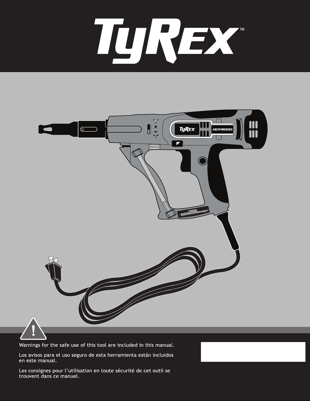
● Read and understand all instruc-
Warning!
tions. Failure to follow all instructions
listed below, may result in electric
shock, fire and/or serious personal
injury.
SAVE THESE
INSTRUCTIONS
Work Area
● Keep your work area clean and
well lit. Cluttered benches and dark
areas invite accidents.
● Do not operate power tools in
explosive atmospheres, such as in
the presence of flammable liquids,
gases, or dust. Power tools create
sparks which may ignite the dust or
fumes.
● Keep bystanders, children, and
visitors away while operating a
power tool. Distractions can cause
you to lose control.
Advertencia!
● Lea y comprenda todas las instruc-
ciones. La falta de observación de
todas las instrucciones listadas a
continuación puede causar choque
eléctrico, incendios o lesiones graves.
GUARDE ESTAS
INSTRUCCIONES
Zona de trabajo
● Mantenga la zona de trabajo
limpia y en buenas condiciones.
Los bancos de trabajo desordenados y los lugares oscuros son una
invitación a un accidente.
● No haga funcionar herramientas
de motor en atmósferas
explosivas, tal como en presencia
de líquidos, gases o polvos
inflamables. Las herramientas de
motor generan chispas que pueden
encender el polvo o los vapores.
● Mantenga s los acompañantes,
menores y visitas alsjados mientras usted utiliza la herramienta
de motor. Las distracciones
pueden hacer que usted pierda el
control.
Avertissement !
● Maintenez votre zone de travail
propre et bien éclairée. Des étab-
lis en désordre et des zones mal
éclairées augmentent les risques
d’accident.
CONSERVEZ CES
INSTRUCTIONS
Zone de travail
● Maintenez votre zone de travail
propre et bien éclairée. Des
établis en désordre et des zones mal
éclairées augmentent les risques
d’accident.
● N’utilisez pas d’outillage électrique
dans un environnement contenant
des produits explosifs comme
des liquides inflammables, gaz ou
poussières. De l’outillage électrique
génère des étincelles qui peuvent
enflammer la poussière ou les
vapeurs.
● Maintenez les spectateurs,
enfants et visiteurs à l’écart
lorsque vous utilisez de
l’outillage électrique. Toute dis-
traction risque de vous faire perdre
le contrôle de votre outil.
Electrical Safety
● Double insulated tools are
equipped with a polarized plug
(one blade is wider than the
other.) This plug will fit in a
polarized outlet only one way. If
the plug does not fit fully in the
outlet, reverse the plug. If it still
does not fit, contact a qualified
electrician to install a polarized
outlet. Do not change the plug
in any way. Double insulation
eliminates the need for the three
wire grounded power cord and
grounded power supply system.
● Avoid body contact with grounded
surfaces such as pipes, radiators,
ranges and refrigerators. There is
an increased risk of electric shock if
your body is grounded.
Seguridad Electrica
● Las herramientas con aislante
doble cuentan con un enchufe
polarizado (una clavija es más
ancha que la otra.) Este enchufe se
puede insertar en un tomacorriente
polarizado de una sola manera.
Si el enchufe no se introduce
totalmente en el tomacorriente,
dé vuelta el enchufe. Si todavía no
entra, solicite a un perito electricista que instale un tomacorriente
polarizado. No le haga ningún tipo
de modificación al enchufe. El
aislante doble elimina la necesidad
de un cordón de alimentación trifilar
conectado a tierra y de un sistema
de suministro eléctrico conectado a
tierra.
●
Evite el contacto del cuerpo con las
superficies conectadas a tierra, por
ejemplo, tubos, radiadores, cocinas y
refrigeradores. Existe un riesgo mayor de
sufrir un electrochoque si su cuerpo está
conectado a tierra.
Sécurité Électrique
● Les outils à isolation double ont
une fiche polarisée (une borne
est plus large que l’autre). Elle
ne peut s’enficher dans une prise
polarisée que d’une façon. Si elle
ne s’enfiche pas, inversez-la. Si
le problème persiste, contactez
un électricien qualifié pour
installer une prise polarisée. Ne
modifiez en aucune façon la prise
existante. Cette isolation double
évite le besoin d’un cordon secteur
3 fils et de la liaison de terre sur
tout le système d’alimentation
électrique.
●Évitez le contact corporel avec des
surfaces à la terre comme tuyaux,
radiateurs, cuisinière et réfrigérateur. Vous avez plus de risques
d’électrocution si votre corps est mis
à la terre.
3
Page 4
S a f e t y Warnings ● A v i s o s d e S e g u r i d a d ● Consignes de Sécurité
English Espanol Francais
●
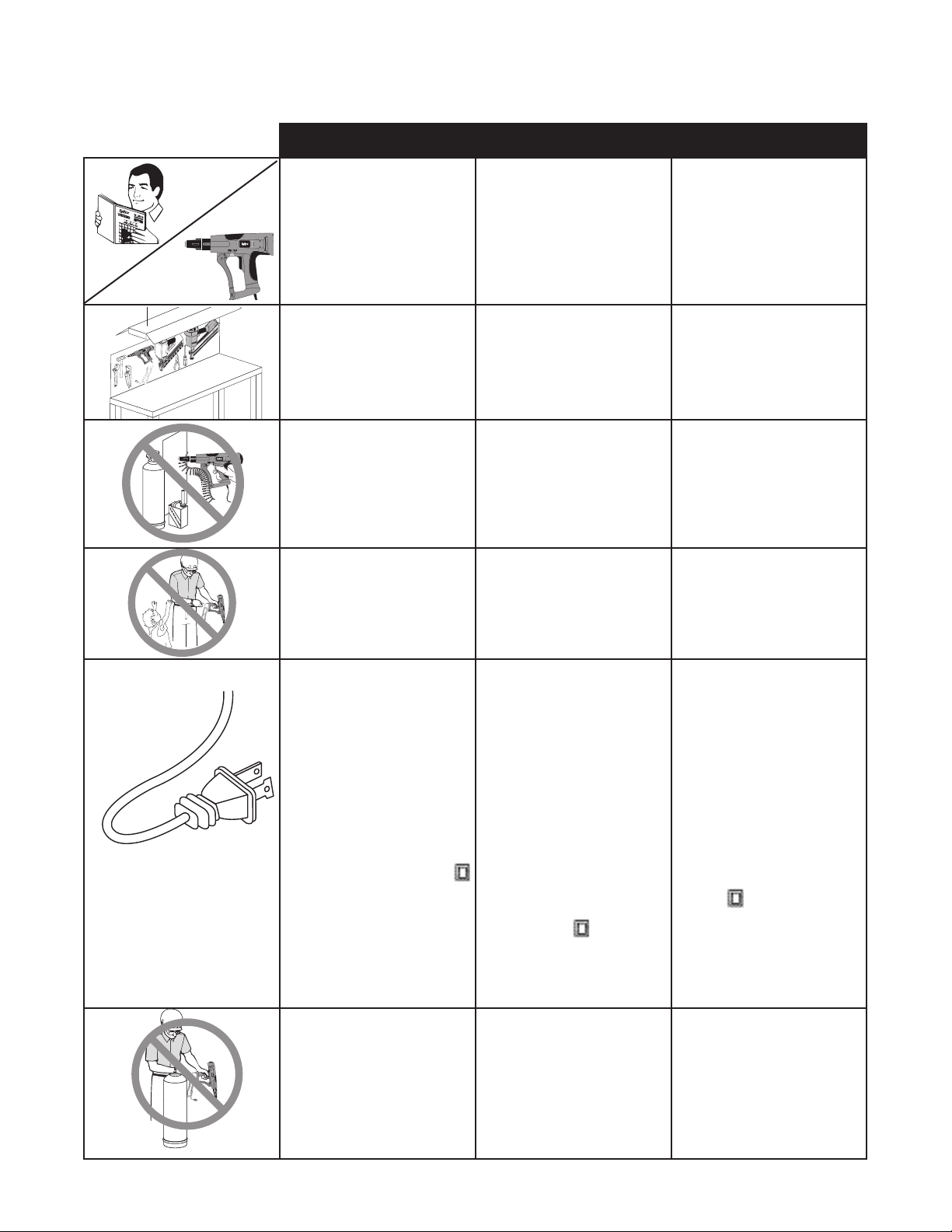
● Don’t expose power tools to rain
or wet conditions. Water entering
a power tool will increase the risk of
electric shock.
No exponga las herramientas eléctricas
a la lluvia o condiciones húmedas. El
agua que entra a una herramienta eléctrica
aumenta el riesgo de electrochoque.
● N’exposez pas les outils élec-
triques à la pluie ou à l’humidité.
Une infiltration d’eau dans l’outil
augmente le risque d’électrocution.
Length of Cord (Feet)
25 50 100 150
AWG Size of Cord
16 16 16 14
Largo del cable (m [pies])
7,5 15 30 45
Calibre AWG del cable
16 16 16 14
Longueur du cordon (en m)
7,5 15 30 45
Taille AWG du cordon
16 16 16 14
Electrical Safety
● Do not abuse the cord. Never use
the cord to carry the tools or pull
the plug from an outlet. Keep
cord away from heat, oil, sharp
edges or moving parts. Replace
damaged cords immediately.
Damaged cords increase the risk of
electric shock.
● When operating a power tool
outside, use an outdoor extension cord marked “W-A” or “W”.
These cords are rated for outdoor
use and reduce the risk of electric
shock. When using an extension
cord, be sure to use one heavy
enough to carry the current your
product will draw. An undersized
cord will cause a drop in line voltage
resulting in loss of power and overheating. The following table shows
the correct size to use depending on
cord length and nameplate ampere
rating. If in doubt, use the next
heavier gage. The smaller the gage
number, the heavier the cord.
Seguridad eléctrica
●
No maltrate el cordón eléctrico.
No use el cordón para acarrear las
herramientas o para desenchufarlas
de un tomacorriente. Mantenga el
cordón lejos del calor, aceite, borde
afilados o piezas en movimiento.
Sustituya inmediatamente los cordones dañados. Los cordones dañados
aumentan el riesgo de electrochoque.
●
Cuando trabaje con una herramienta
eléctrica a la intemperie, use un cordón
alargador de exterior marcado «W-A»
o «W». Estos cordones son clasificados
para uso exterior y reducen el riesgo de
electrochoque. Cuando utilice un cordón
alargador, asegúrese de que sea lo bastante
grueso para conducir la corriente que su
herramienta va a consumir. Un cordón de
calibre insuficiente causará una caída en
la tensión de línea dando por resultado la
pérdida de potencia y sobrecalentamiento.
En la tabla siguiente se indican las medidas
correctas a utilizar de acuerdo a la longitud
del cordón y al amperaje de servicio. Ante
cualquier duda, utilice el próximo calibre
más grueso.
Cuanto menor el número de calibre, tanto
más grueso es el cordón.
Sécurité électrique
● Ne maltraitez pas le cordon, pour
porter l’outil ou en le tirant pour
le débrancher. Gardez-le loin de
chaleur, huile, arêtes tranchantes
ou pièces mobiles. Remplacez-le
tout de suite s’il est abîmé. Un
cordon endommagé crée un risque
d’électrocution.
● En utilisant un outil électrique
dehors, prenez un cordon rallonge avec label “W-A” ou “W”.
Ce sont des cordons conçus pour
l’extérieur à risque d’électrocution
réduit. Choisissez-le bien dimensionné pour la puissance qui sera
tirée par votre produit. Un cordon
sous dimensionné provoque une
chute en ligne de la tension secteur,
d’où perte de puissance en bout et
échauffement. Le tableau qui suit
montre le bon calibre à utiliser en
fonction de la longueur à prolonger
et de la consommation nominale
de l’appareil à brancher. En cas de
doute, prenez un calibre supérieur.
Plus le numéro de calibre est petit,
plus gros est le cordon.
Personal Safety
● Stay alert, watch what you are
doing, and use common sense
when operating a power tool. Do
not use tool while tired or under
the influence of drugs, alcohol, or
medication. A moment of inatten-
tion while operating power tools may
result in serious personal injury.
● Dress properly. Do not wear loose
clothing or jewelry. Contain long
hair. Keep your hair, clothing, and
gloves away from moving parts.
Loose clothes, jewelry, or long hair
can be caught in moving parts.
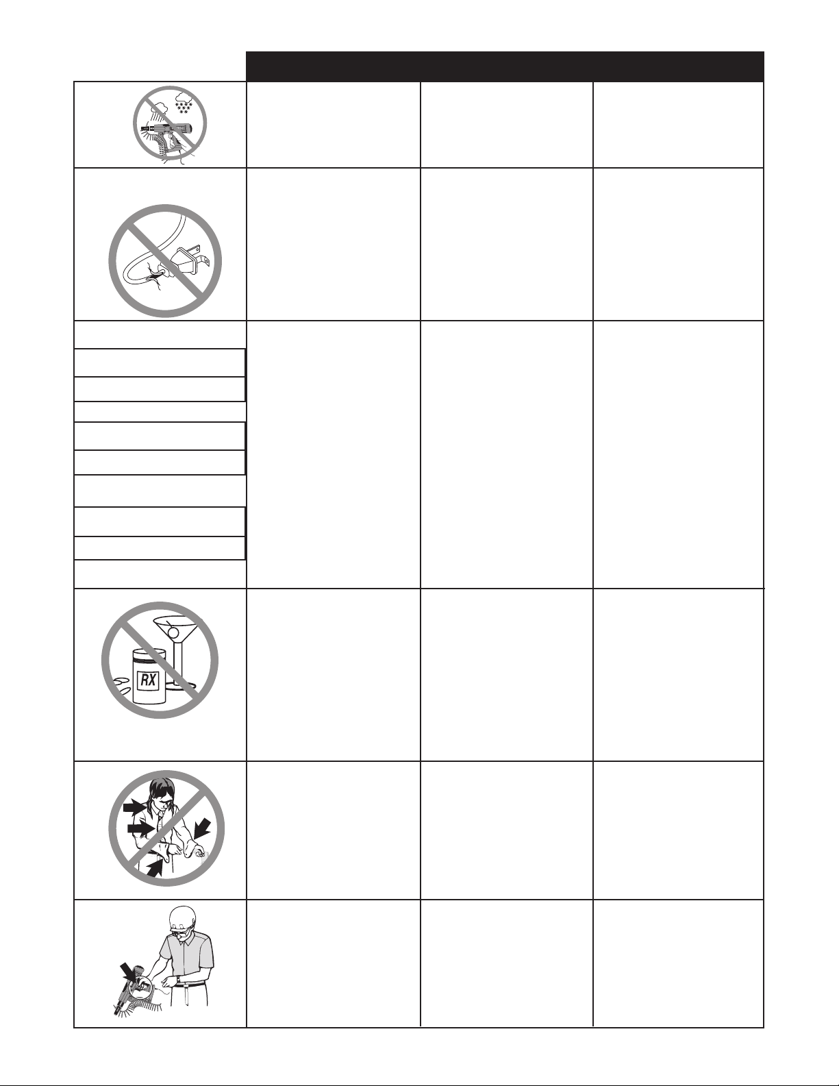
● Avoid accidential starting. Be
sure switch is off before plugging
in. Carrying tools with your finger
on the switch or plugging in tools
that have the switch on invites
accidents.
Seguridad personal
● Cuando utilice una herramienta de
motor, manténgase a;erta, preste
atención a lo que está haciendo
y aplique el sentido común. No
use la herramienta cuando se
sienta cansado o se encuentre
bajo los efectos de drogas, alchol o
medicamentos. Un momento de falta
de atención mientras utiliza una herramienta de motor puede ocasionar
lesiones graves.
● Vista prendas adecuadas. No
vista prendas o alhajas sueltas.
Sujete el calbello largo. Mantenga
el cabello, la ropa y los guantes
alejados de las piezas móviles. Las
prendas o alhajas sueltas o el cabello
pueden ser atrapados en las partes
móviles.
● Evite los arranques accidentales.
Quite siempre el dedo del gatillo
cuando no esté disparando clavos.
Nunca cargue la herramienta con
el dedo sobre o por debajo del
gatillo. La herramienta dispara un
clavo si se golpea el elemento de
seguridad.
Sécurité corporelle
● Soyez en bonne condition
physique, soyez attentif à ce que
vous faites et faites preuve de
bon sens lorsque vous utilisez un
outillage électrique. N’utilisez pas
votre outil si vous êtes fatigué
ou sous l’influence de drogues,
alcool ou médicaments. Un moment
d’inattention lors de l’utilisation d’un
outillage électrique peut être la cause
de graves blessures corporelles.
● Portez des vêtements adéquats.
Ne portez pas de vêtements
flottants ou de bijoux. Ne laissez
pas pendre les cheveux longs.
Maintenez les cheveux, vêtements
et gants à distance des objets
en mouvement. Les vêtements
flottants, cheveux longs ou bijoux
peuvent être happés par des pièces
en mouvement.
● Faîte attention aux mises en
routes accidentelles de l’outil.
Otez le doigt de la détente
lorsque vous n’enfoncez pas
d’agrafes. Ne transportez
jamais l’outil avec le doigt sur la
détente; l’outil tirera une agrafe
si le palpeur de sécurité est
heurté.
4
Page 5
S a f e t y Warnings ● A v i s o s d e S e g u r i d a d ● Consignes de Sécurité
English Espanol Francais
● Remove adjusting keys or
wrenches before turning the tool
on . A wrench or a key that is left
attached to a rotating part of the
tool may result in personal injury.
● Retire las llaves o pinzas de
ajuste antes de encender la herramienta. Una llave o pinza que
quede colocada sobre una parte
giratoria puede ocasionar lesiones.
● Retirez toute clé de réglage de
l’outil avant sa mise en service.
Toute clé restée attachée à une
pièce en rotation de l’outil peut
provoquer des blessures corporelles.
● Do not overreach. Keep proper
footing and balance at all times.
Proper footing and balance enable
better control of the tool in unexpected situations.
● Use safety equipment. Always
wear eye protection. Dust mask,
non-skid safety shoes, hard hat, or
hearing protection must be used
for appropriate conditions. Failure
to do so could result in personal
injury.
Tool Use and Care
● Use clamps or other practical
ways to secure and support the
workpiece to a stable platform.
Holding the work by hand or against
your body is unstable and may
lead to loss of control and personal
injury.
● Do not force tool. Let the tool do
the work. Use the correct tool for
your application. The correct tool
will do the job better and safer at
the rate for which it is designed.
● No se estire para trabajar.
Mantenga en todo momento una
posición adecuada y el equilibrio.
La posición y el equilibrio adecuados le permiten contrilar mejor
la herramienta ante situaciones
inesperadas.
● Use equip de seguridad. Use
siempre protección para los
ojos. A fin de trabajar en las
condiviones apropiadas, debe usar
máscara para polvo, calzado de
seguridad antideslizante, casco
duro o protección para los oídos.
El no utilizar estos elementos
puede ocasionar lesiones.
Uso y cuidado de la
herramienta
● use mordazas u otro método
práctico para asegurar y soportar
el lugar de trabajo en una
plataforma estable. El sostener
la pieza de trabajo con la mano o
contra el cuerpo resulta inestable y
puede ocasionar pérdida del control
y lesiones.
● No fuerce la herramienta. Deje
que la herramienta haga su
trabajo. utilice la herramienta
adecuada para la aplicación
requerida. La herramienta correcta
podrá hacer el trabajo mejor y con
más seguridad a la velocidad para
la que fue diseñada.
● Ne présumez pas de vos forces.
Restez bien stable et en équilibre
à tout moment. Une position stable
et bien équilibrée vous permettra
de mieux réagir à une situation
inattendue.
● Utilisez des équipements de sécu-
rité. Portez toujours des lunettes
de protection. Utilisez un masque
de protection contre la poussière,
des chaussures antidérapantes, un
casque et des protections auditives
pour travailler dans les meilleures
conditions. Un manquement à ces
règles de sécurité peut provoquer des
accidents corporels.
Utilisation de l’outil et précautions
● Utilisez des valets d’établi ou tout
autre moyen pour assurer un
maintien correct de la pièce sur
un plan stable. Maintenir la pièce
à la main ou contre votre corps
est instable et peut entraîner une
perte de contrôle et des accidents
corporels.
● Ne forcez pas sur l’outil, laissez-
le faire le travail. Utilisez l’outil
approprié à votre type de travail.
L’utilisation de l’outil adéquat vous
permettra d’effectuer votre travail
au mieux et dans de meilleures
conditions de sécurité au rythme
pour lequel il a été conçu.
● Do not use tool if switch does not
turn it on or off. Any tool that cannot be controlled with the switch is
dangerous and must be repaired.
● Disconnect the plug from the
power source before making any
adjustments, changing accessories, or storing the tool. Such pre-
ventive safety measures reduce the
risk of starting the tool accidentally.
● No use la herramienta si el inter-
ruptor no la puede encender o
apagar. Toda herramienta que no
puede controlarse con el interruptor
es peligrosa y se debe reparar.
● Desconecte el enchufe de la
fuente de alimentación antes de
hacer ajustes, cambiar los accesorios o guardar la herramienta.
Estas medidas preventivas reducen
el riesgo de activar la herramienta
accidentalmente.
5
● N’utilisez pas un outil à
l’interrupteur M/A défectueux.
Tout outil qui ne peut pas être
contrôlé par l’interrupteur est
dangereux et à réparer.
● Débranchez la fiche secteur de la
prise avant tout réglage, changement d’accessoire ou stockage.
Cette mesure de sécurité préventive élimine le risque de démarrage
intempestif de l’outil.
Page 6

S a f e t y Warnings ● A v i s o s d e S e g u r i d a d ● Consignes de Sécurité
Authorized
Service Center
TM
English Espanol Francais
● Store idle tools out of reach of
children and other untrained
persons. Tools are dangerous in the
hands of untrained users.
● Almacene todas las herramientas
lejos del alcance de los menores
u otras personas no capacitadas.
Las herramientas son peligrosas en
manos de los usuarios no capacitados.
● Rangez les outils non utilisés à
l’abri des enfants ou autres personnes non exercées à leur maniement. Les outils sont dangereux dans
des mains non expertes.
● Maintain tools with care. Keep
cutting tools sharp and clean.
Properly maintained tools, with
sharp cutting edges are less likely
to bind and are easier to control.
● Check for misalignment or bind-
ing of moving parts, breakage of
parts, and any other condition that
may affect the tool’s operation
and safety. If damaged, have the
tool serviced before using. Many
accidents are caused by poorly
maintained tools.
● Use only accessories that are rec-
ommended by the manufacturer
for your model. Accessories that
may be suitable for one tool may
create a risk of injury when used on
another tool.
Service
● Tool service must be performed
only by Authorized TyRex repair
personnel. Service or maintenance
performed by unqualified personnel
may result in a risk of injury.
● Cuide el mantenimiento de las
herramientas. Las herramientas
bien mantenidas tienen menos
probabilidades de agarrotarse y
resulta más sencillo controlarlas.
● Verifique si las partes móviles no
están desalineadas o agarrotadas,
si hay piezas rotas o si existe
alguna otra condición que pueda
afectar el funcionamiento y la
seguridad de la herramienta. Si la
herramienta está dañada, hágala
reparar antes de utilizarla. Muchos
accidentes se deben a herramientas
mal mantenidas.
● Use sólo accesorios recomen-
dados por el fabricante de su
modelo. Los accesorios que resultan
apropiados para un modelo pueden
crear riesgos de lesiones cunado se
utilizan con otra herramienta.
Servicio técnico
● Las tareas de servicio técnico de la
herramienta deben ser realizadas
sólo por personal de reparaciones
de TyRex autorizado. Las tareas de
servicio o mantenimiento realizadas
por personal no clificado purden
ocasionar riesgos de lesiones.
● Entretenez l’outil avec soin. Des
outils correctement entretenus
diminuent les risques de grippage
et sont plus faciles à maîtriser.
● Vérifiez qu’il n’y a pas de mauvais
alignement ou grippage des pièces
en mouvement, ou toute autre
condition qui pourrait affecter le
bon fonctionnement de l’outil ou
compromettre la sécurité. Si vous
constatez un dommage quelconque, faites réparer l’outil avant
de l’utiliser. Des outils mal entre-
tenus sont à l’origine de beaucoup
d’accidents.
● N’utilisez que des accessoires
recommandés par votre fabricant
et adaptés à votre modèle d’outil.
Des accessoire conçus pour un
type d’outil peuvent provoquer des
risques d’accident s’ils sont utilisés
sur un autre modèle.
Entretien
● L’entretien de l’outil ne doit être
assuré que par du personnel
autorisé et qualifié de TyRex. De
l’entretien assuré ou des réparations
effectuées par du personnel non
qualifié peuvent occasionner des
risques d’accident.
● When servicing a tool, use only
identical replacement parts.
Follow instructions in the
Maintenance section of this
manual. Use of unauthorized parts
or failure to follow Maintenance
Instructions may create a risk of
electric shock or injury.
● Cuando realice tareas de servicio
en una herramienta, use sólo
piezas de repuesto idénticas. Siga
las instrucciones de la sección de
Mantenimiento de este manual. El
uso de piezas no autorizadas o la falta
de observación de las instrucciones
de mantenimiento puede ocasionar
riesgos de choque eléctrico o
lesiones.
6
● Lors d’un entretien ou d’une
réparation, n’utilisez que des
pièces de rechange identiques.
Suivez les instructions de
ce manuel dans la section
maintenance. L’utilisation de
pièces non autorisées ou un
manquement aux règles de
maintenance peut provoquer un
risque d’électrocution ou des
blessures.
Page 7

S a f e t y Warnings ● A v i s o s d e S e g u r i d a d ● Consignes de Sécurité
Specific Safety Rules and/or Symbols
English Espanol Francais
Symbol Definitions
V............volts
A............amperes
Hz..........hertz
W...........watts
min........minutes
........alternating current
.....direct current
n
o...........no load speed
..........Class II Construction
…/min.....revolutions per minute
.........earthing terminal
..........safety alert symbol
Symbol Definitions Symbol Definitions
V............voltios
A............amperios
Hz..........hertzios
W............vatios
min.........minutos
..........corriente alterna
.....corriente continua
n
o...........velocidad sin carga
..........Construcción de Clase II
…/min.....revoluciones o vaivén por minuto
..........erminal de puesta a tierra
..........símbolo de alerta de seguridad
V.............volts
A.............ampères
Hz...........hertz
W............watts
min.........minutes
.........courant alternatif
.......courant continu
n
o...........vitesse sans charge
..........construction Classe II
…/min.....tours/minute dans un sens ou l’autre
..........borne de mise à la terre
..........symbole d’alerte de sécurité
7
Page 8

S a f e t y Warnings ● A v i s o s d e S e g u r i d a d ● Consignes de Sécurité
W
A
RN
IN
G
English Espanol Francais
● Hold tool by insulated gripping
surfaces when preforming an
operation where the cutting tool
may contact hidden wiring or its
own cord. Contact with a “live” wire
will make exposed metal parts of the
tool “live” and shock the operator.
● Do not use tool without Warning
Label on tool. If label is missing,
damaged or unreadable, contact
your TyRex representative to obtain a
new label at no cost.
● Cuando taladre en paredes, pisos
o en todo lugar en el que puedan
encontrarse cables elécticos alimentados (“vivos”), NO TOQUE NINGUNA
DE LAS PARTES METÁLICAS DE
LA HERRAMIENTA, Sostenga la
herramienta sólo por las superficies
aisladas a fin de impedir el choque
eléctrico si usted se encuentra con un
cale “vivo”.
● No use la herramienta sin la etiqueta
de Avisos de Seguridad. Si la etiqueta esta dañada, no se puede leer o
falta completamente. Comuníquese
con su representante de TyRex para
obtener una etiqueta nueva.
● NE TOUCHEZ À AUCUNE PARTIE
MÉTALLIQUE DE L’OUTIL si vous
devez percer dans des murs ou
planchers où peuvent se trouver des
conducteurs électriques sous tension.
Maintenez l’outil par ses parties
isolées pour prévenir tout risque
d’électrocution s’il arrive que vous
percez un conducteur sous tension.
● N’utilisez pas l’appareil sans
l’étiquette de sécurité. Si l’étiquette
est manquante, endommagée ou
illisible, prendre contact avec votre
représentant TyRex pour en obtenir
une autre.
Functional Description ● Funcional Descripción ● Functional Description
Bit Release
Depth of Drive Indicator
Adjustable
Nose Piece
Wrench Holder
Depth of Drive Control
Reverse Switch
Belt Hook
Trigger Lock
Variable Speed
Trigger
Bit Holder
10 ft. Cord
8
Page 9

To ol Ope rat ion ● Oper ació n d e l a H err ami ent a ● Uti lis ati on de l ’Ou til
English Espanol Francais
● Read and understand all instruc-
tions. Failure to follow all instructions
listed below, may result in electric
shock, fire and/or serious personal
injury.
SAVE THESE
INSTRUCTIONS
● Loading the Tool:
Check to be sure the heads of the
screws are resting on top of the
plastic collation material. This will
prevent damage to the strip guide.
● Check for proper fastener length
setting (see “Setting the fastener
length” page 8).
● Feed the strip into the strip
guide.
● Lea y comprenda todas las instruc-
ciones. La falta de observación de
todas las instrucciones listadas a
continuación puede causar choque
eléctrico, incendios o lesiones graves.
GUARDE ESTAS
INSTRUCCIONES
● Carga de la herramienta:
Asegúrese de que las cabezas de los
tornillos descansen contra el material
plástico de intercalación. De este
modo, se evitarán daños a la guía de
la faja.
● Verifique que el largo del tornillo
sea el adecuado ( vea “Ajuste del
largo del tornillo”, en la página 8).
● Inserte la faja en la guía para faja.
● Maintenez votre zone de travail
propre et bien éclairée. Des établis en désordre et des zones mal
éclairées augmentent les risques
d’accident.
CONSERVEZ CES
INSTRUCTIONS
● Chargement de l’outil :
Vérifiez que les têtes des vis reposent
bien sur le sommet de la bande
collectrice en plastique pour éviter
d’endommager le guide.
● Vérifiez que la longueur de la fixa-
tion est correctement ajustée (voir
« Ajustement de la longueur de la
fixation » page 8).
● Alimentez la bande dans le guide.
● Move the strip forward until the 2nd
empty slot is aligned with the bit.
This will allow for the proper strip
advancement once the nosepiece is
depressed.
● To remove the strip, pull it
through from the top of the
nosepiece.
● Whenever possible, hold the tool at
a right angle to the work surface.
● (1) Pull the trigger to start the motor.
● Haga avanzar la faja hasta que la
2da. ranura vacía quede alineada
con la broca. De este modo, se permitirá que la faja avance en forma
adecuada se presione la pieza de
la boca.
● Para retirar la faja, tire de la
misma desde la parte superior
de la pieza de la boca.
● Siempre que resulte posible, sos-
tenga esta herramienta en ángulo
recto respecto de la superficie de
trabajo.
● (1) Presione el accionador para
arrancar el motor.
● Faîtes avancer la bande jusqu’à ce
que la 2
ème
fente vide soit alignée
avec la broche. Ceci permettra un
avancement correct de la bande dès
que l’on fera pression sur le nez.
● Pour enlever la bande, tirez-
la à travers le dessus du nez.
● Chaque fois que cela est possible,
maintenez l’outil perpendiculairement à la surface de travail.
● (1) Appuyez sur la gâchette pour
démarrer le moteur.
9
Page 10

To ol Ope rat ion ● O per aci ón d e la H err ami e nta ● U til isa tio n d e l ’Ou til
English Espanol Francais
● (2) Press the nosepiece, with constant
force, against the work surface. Do not
remove the tool from the work surface
until the clutch disengages and the bit
stops rotating, signaling a fully driven
screw.
● (3) Continue to allow the motor to
run. The next screw will be automatically fed into place when the
tool is being depressed against the
work surface.
● To lock the switch in the on position
for continuous operation, depress
the trigger switch and push in
the locking button. The tool will
continue to run. To turn the tool off,
from a locked on condition, squeeze
and release the trigger once. Before
using the tool (each time), be sure
that the locking button release
mechanism is working freely.
● (2) Presione la pieza de la boca,
ejerciendo una fuerza constante,
contra la superficie de trabajo. No
retire la herramienta de la superficie
de trabajo hasta que el embrague se
desenganche y la broca deje de girar,
lo que indica que el tornillo se ha
embutido totalmente.
● (3) Continúe haciendo funcionar
el motor. El siguiente tornillo se
alimentará automáticamente
cuando se ejerza presión contra la
superficie de trabajo.
● Para bloquear el interruptor en
la posición de encendido para
funcionamiento continuo, oprima
el gatillo y pulse el botón de blo-
queo. La herramienta continuará
funcionando.
Para apagar la herramienta,
desde una condición de encendido
continuo, oprima y suelte el gatillo
una sola vez. Antes de usar la
herramienta (cada vez), cerciórese
de que el mecanismo soltador
del botón de bloqueo funcione
libremente.
● (2) Appuyez le nez sur la surface de
travail avec une pression constante.
N’enlevez pas l’outil de la surface
de travail avant débrayage et arrêt
de la rotation de la broche indiquant
que l’opération de vissage est
complètement terminée.
● (3) Appuyez de nouveau sur la
gâchette pour permettre au moteur
de tourner. La vis suivante sera
automatiquement alimentée à sa
place dès que vous appuierez l’outil
sur la surface de travail.
● Pour bloquer la détente en position
pour un fonctionnement en continu
sans avoir à la maintenir, appuyez
dessus et pressez le bouton de
blocage. L’outil va continuer à
tourner. Pour le couper à partir de ce
mode, appuyez de nouveau sur la
détente et relâchez-la. Avant chaque
démarrage de l’outil, vérifiez que le
mécanisme de libération du bouton
de blocage fonctionne bien.
● This tool is equipped with a depth
control adjustment.
● Test drive one screw before final-
izing the depth to ensure appropriate
depth of drive.
● Adjust the depth of drive by turning
the depth adjustment thumbwheel:
Refer to the graphics on the tool for
proper direction.
● This tool has a depth-sensing clutch.
When the screw is countersunk to
the pre-set depth, it automatically
disengages and makes a click or
racheting sound. This is normal and
signals completion of the drive.
● Esta herramienta está equipada con
un ajuste de control de profundidad.
● Inserte un tornillo de prueba antes
de llegar al máximo de la profundidad a fin de asegurar que se cuenta
con la profundidad de embutido
apropiada.
● Para ajustar la profundidad de em-
butido, haga girar la perilla de ajuste
de profundidad. Consulte la dirección
de giro correcta en los gráficos
ilustrados en la herramienta.
● Esta herramieenta tiene un em-
brague que determina la profundidad. Cuando el tornillo se embute a
una profundidad preconfigurada, el
embrague se desacopla automáticamente y hace un clic o un sonido de
trinquete. Esto es normal e indica la
finalización del impulso.
● Cet outil est équipé d’un système de
réglage de la profondeur.
● Faites un essai avec une vis avant
de procéder au réglage final de la
profondeur afin de vous assurer que
la pénétration est correcte.
● Réglez la pénétration en tournant la
molette de réglage de la profondeur :
Référez-vous au graphique figurant
sur l’outil pour trouver la bonne
direction.
● Cet outil posséde un dispositif
de mesure de profondeur avec
débrayage. Lorsque la vis arrive
à la profondeur prédéterminée, le
dispositif se débraie automatiquement et produit un clic, signifiant que
le vissage est terminé.
10
Page 11

To ol Ope rat ion ● O per aci ón d e la H err ami e nta ● U til isa tio n d e l ’Ou til
English Espanol Francais
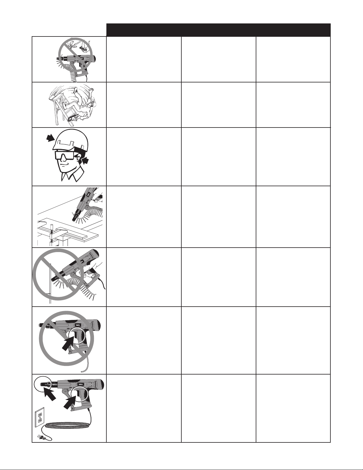
● Changing the bit:
Due to wear or damage, the bit will
need to be replaced periodically
or when changing from Phillips to
Square Drive fasteners.
● Remove fasteners from the tool. (1)
Pull bit release button to rear. (2) Tilt
tool downward and pulse motor. Bit
will fall out.
● (1) Hold tool upright. Insert the new
bit into the slide body. (2) Pull bit
release button to rear. (3) Pulse tool
and release button when bit drops
into place.
Adjusting Fastener
Length
● Unplug tool from electrical supply
before adjusting nosepiece for
fastener length.
● Cambio de la broca:
La broca se deberá reemplazar
periódicamente a causa del desgaste o daños o cuando se cambia
de tornillos Phillips a tornillos para
broca de punta cuadrada.
● Retire los tornillos de la herramienta.
(1) Tire de botón de liberación de la
broca hacia atrás. (2) Incline la herramienta hacia adelante y mueva el
motor a pulso. La broca caerá.
● (1) Sostenga la herramienta en
posición recta. Inserte la nueva
broca en el cuerpo seslizante. (2)
Tire de botón de liberación de la
broca hacia atrás. (3) Pulse el botón
y libérelo cuando la broca calce en
su posición.
Ajuste del largo del
tornillo
● Desenchufe la herramienta de la
fuente de alimentaciûn elèctrica
antes de ajustar la pieza de boca al
largo del tornillo.
● Changement de la broche :
La broche doit être remplacée péri-
odiquement en raison d’usure ou de
dommage ou de changement entre
vis à tête Phillips ou carrées.
● Retirez les vis de l’outil. (1) Tirez le
bouton de libération de la broche
vers l’arrière. (2) Inclinez l’outil
vers le bas et faites tourner le
moteur. La broche doit tomber.
● (1) Tenez l’outil vers le haut.
Insérez la nouvelle broche dans
son logement. (2) Appuyez sur la
gâchette et relâchez une fois la
broche en position.
Réglage de la longueur
de fixation
● Avant díajuster líextrèmitè rotative
en fonction de la longueur de la
fixation, níoubliez pas de dèbrancher líoutil.
● Remove screw using supplied allen
wrench.
● Align marks on the nosepiece with
edge of the feed housing for proper
fastener lengths.
● Nosepiece has settings;
DCF5000
1’’ 1st hole 25mm
1/4
1
’’ 2nd hole 32mm
1/2
1
’’ 3rd hole 38mm
5/8
1
’’ 4th hole 41mm
3/4
1
’’ 5th hole 44mm
2’’ 6th hole 50mm
● To tighten screw,depress the nose-
piece using slight pressure. Tighten
the screw, making sure it is snug
against the slidebody.
● Retire el tornillo usando la llave
allen provista
● Para ajustar los largos de tornillo
apropiados, alinee las marcas de
la boca de la herramienta con el
borde de la ranura de alimentación.
● La boca puede configurarse en seis
posibles;
DCF5000
1’’ 1˚orificio 25mm
1/4
1
’’ 2˚orificio 32mm
1/2
1
’’ 3˚orificio 38mm
5/8
1
’’ 4˚orificio 41mm
3/4
1
’’ 5˚orificio 44mm
2’’ 6˚orificio 50mm
● Para apretar el tornillo, presione
la pieza de la boca ejerciendo
ligera presión. Apriete el tornillo,
asegurándose de que calce bien
contra el cuerpo deslizable.
● Avec une clè Allen, enlevez la vis.
● Alignez les marques du nez avec
le bord du logement d’alimentation
pour un réglage correct des longueurs de fixation.
● Il y a possibles du nez ;
DCF5000
1’’ 1st trou 25mm
1/4
1
’’ 2nd trou 32mm
1/2
1
’’ 3rd trou 38mm
5/8
1
’’ 4th trou 41mm
3/4
1
’’ 5th trou 44mm
2’’ 6th trou 50mm
● Pour serrer la vis, imprimez une
légère pression sur le nez. Serrez
la vis en vous assurant qu’elle
est bien ajustée contre la partie
coulissante.
11
Page 12

M a i n t e n a n c e ● M a n t e n i m i e n t o ● E n t r e t i e n
R
English Espanol Francais
● Read section titled “Safety Warnings”
before maintaining tool.
● With tool unplugged from electrical
supply, make daily inspection to
assure free movement of nosepiece
and trigger. Do not use tool if nosepiece or trigger sticks or binds.
● Routine lubrication of the attach-
ment is not necessary. Do not oil.
● Follow manufacturers
recommendations for the screwdriver.
● Wipe tool clean daily and inspect for
wear.
● Lea la sección titulada “Avisos de
Seguridad” antes de darle mantenimiento a la herramienta.
● Desenchufe la herramienta de la
fuente de alimentaciûn elèctrica,
efecte la inspecciûn diaria para asegurar el movimiento libre de la pieza
de la boca y el accionador. No use la
herramienta si la pieza de la boca o
el accionador se quedan pegados o
unidos entre sí.
● La lubricación de rutina no es
necesaria. No aceite.
● Respete las recomendaciones de
los fabricantes para la herramienta
colocadora de tornillos.
● Limpié la herramienta frotán-
dola e inspeccione para ver si hay
desgaste.
● Lisez la section intitulée “Consignes
de Sécurité” avant d’effectuer
l’entretien de l’outil.
●Alors que líoutil est dèbranchè, faites
une inspection quotidienne pour vous
assurer que la dètente et líextrèmitè
rotative bougent librement.N’utilisez
pas l’outil s’il y a blocage ou grippage du nez ou de la gâchette.
● La lubrification de routine n'est pas
nécessaire. N'huilez pas.
● Suivez les recommandations du
fabricant du tournevis èlectrique.
● Nettoyez l’outil chaque jour à l’aide
d’un chiffon et inspectez-le pour
déceler une éventuelle usure.
12
Page 13

T r o u b l e s h o o t i n g ● I d e n t i f i c a c i ó n d e F a l l a s ● D é p a n n a g e
Problem or Symptom
Tool will not start or runs slowly.
Tool will not drive screw into desired substrate.
Tool does not fully drive fastener.
Tool does not advance fastener.
Screws fall out of collation during drive.
Bit will not install.
Bit slips off screw or screw is driven at an angle.
Fastener Jams
Slide Mechanism “sticks” or returns slowly.
Tool Overheats
Probable Cause
Trigger switch is defective.
Broken motor lead.
No electrical power.
Damaged cord.
Bit is worn.
Power capabilities of the tool have been exceeded.
Depth of drive not set properly.
Bit is worn or clogged.
Excessive spring debris.
Tool is in reverse.
Screw length is improperly set.
Return spring is weak.
Defective collation material.
Worn sprocket.
Screw riding high in collation.
Collation excessively hot.
Nose Piece loose.
Bit guide has worn.
Bit not properly inserted into drive shaft.
Not a TyRex bit.
Tool is slid forward during drive.
Tool is misaligned.
Bit guide has worn.
Screw length improperly set.
“Nosepiece” screw is loose.
Bit guide has worn.
Screw not seated properly in collation material.
Bit severely worn.
“Nosepiece” damaged or bent.
Debris build-up in mechanism.
Bent Nosepiece.
Weak return spring.
Tough drive application requires too much torque.
Clogged vents.
Corrective Action
Replace trigger switch.
Replace wiring harness.
Check power source. (fuse)
Replace cord.
Replace bit.
Refer to operators manual for appropriate applications.
Adjust depth of drive for deeper penetration.
Replace or clean bit.
Replace or clean spring.
Check for forward operation.
Refer to operators manual to adjust screw length.
Replace return spring.
Return to authorized TyRex service representative.
Replace slide body assembly.
Correct by hand or replace strip.
Keep strips in shade or cool location.
Hold tool firmly while driving.
Replace slide body assembly.
Drop bit straight into opening. Rotate. Push hard.
Return to authorized TyRex service repesentative.
Replace bit.
Try another strip of fasteners.
Replace slide body assembly.
Refer to manual for adjustment of screw length.
Tighten screw.
Replace slide body assembly.
Try another strip of fasteners.
Replace bit.
Replace “Nosepiece”.
Clean mechanism.
Replace Nosepiece.
Replace return spring.
Allow tool to cool and discontinue use in this application.
Be sure vents are open and free of debris.
Pushing force becomes excessive
Bit falls out.
Bit does not release.
Feed mechanism “locks up”.
Slide body has worn.
Improper installation.
Worn drive shaft assembly.
Clutch faces not aligned.
Mechanism jammed.
Latch lever bound up.
Latch spring broken.
ACCESORIES
TyRex offers a full line of
screws and accessories for
your TyRex tools, including:
● Bits
● Case
● Allen Wrenches
● Safety Glasses
For more information or a
complete illustrated catalogue
of TyRex accessories, ask your
representative for #MK336.
Replace slide body. Return to TyRex for service.
Consult manual for proper installation technique.
Replace drive shaft assembly.
Pulse motor while using release button.
Rap bit sharply on workpiece (wood).
Lube (2 drops light oil) latch lever.
Replace latch spring.
TECHNICAL SPECIFICATIONS
DCF5000
Voltage 120v
Current 4.3 amps
Frequency 60Hz
RPM 3300
Weight 4.8 lbs.
Height 8”
Length 15
Width 3”
Fastener 50 screws
Capacity (one strip)
Fastener 1-2”
Range #6-#8
thd.
3/4
”
13
Page 14

T r o u b l e s h o o t i n g ● I d e n t i f i c a c i ó n d e F a l l a s ● D é p a n n a g e
Problema o síntoma
La herranuebta bi arrabca i funciona lentamente.
La herramienta no embute el tornillo en el sustrato
deseado.
La herramienta no embute el tornillo completamente.
La herramienta no hace avanzar el tornillo.
El tornillo cae fuera del material de intercalación
durante el embutido.
El botón de liberación de la broca no libera la broca.
No se puede instalarla broca.
La broca deja caer el tornillo o el tornillo se embute
en ángulo.
Los tornillos se atascan.
El mecanismo de deslizamiento se “pega” o retorna
lentamente.
Recalentamiento de la herramienta.
Causa probable
La batería está descargada o la celda está agotadal.
No hay alimentaciûn elèctricaLa batería. tiene poca
carga.
La broca está gastada.
Se han excedido las capacidades de potencia de la
herramienta.
La profundidad de embutido no se ha ajustado
correctamente.
La broca está gastada o atorada.
El largo del tornillo se ha ajustado incorrectamente.
Material de intercalación defectuoso.
Corona dentada gastada.
El largo del tornillo se ha ajustado incorrectamente.
Las placas del embrague no están alineadas.
La broca no es TyRex.
La broca no está insertada correctamente en el eje
de embutido.
La broca no está alienada correctamente.
El tornillo de la ìpieza de la bocaî est flojo.
La herramienta se hace deslizar hacia abajo durante
el embutido.
La herramienta está desalineadd.
El largo del tornillo se ha ajustado incorrectamente.
El tornillo no está bien asentado en el material de
intercalación.
La broca está muy desgastada.
La pieza de la boca está dañada o doblada.
Acumulación de suciedad en el mecanismo.
Resorte de retorno débil.
Batería descargada.
La aplicación de un impulso muy arduo requiere
demasiado par torsor.
Acción correctiva
Reemplace o recargue la batería.
Verifique la alimentaciûn elèctrica (fusible)
Inserte una batería cargada.
Reemplace la broca.
Consulte en el manual de operaciones las aplicaciones
apropiadas.
Ajuste la profundidad de embutido para lograr una
penetración más profunda.
Reemplace o limpie la broca.
Consulte en el manual de operaciones el ajuste correcto
del largo del tornillo.
Lleve a un representante de servicio autorizado de
TyRex.
Consulte en el manual de operaciones el ajuste correcto
del largo del tornillo.
Sacuda ligeramente la herramienta mientras acciona el
botón de liberación.Use brocas TyRex.
Deje caer la broca en forma recta dentro de la abertura.
Sacuda ligeramente la herramienta mientras acciona el
botón de liberación. Apriete el tornillo
Sostenga la herramienta firmemente durante el embutido.
Lleve a un representante de servicio autorizado de
TyRex.
Consulte en el manual de operaciones el ajuste correcto
del largo del tornillo.
Pruebe con otra tira de tornillos.
Reemplace la broca.
Reemplace la pieza de la boca.
Limpie el mecanismo
Cambie el resorte de retorno.
Permita que la herramienta se enfrie e inserte una
batería cargada.
Permita también que se enfrie y discontinúe el uso en
esta aplicación.
ACCESORIOS
TyRex ofrece una línea
completa de Accesorios para
sus herramientas TyRex,
incluyendo:
● Brocas
● Estuche
● Llaves Allen
● Gafas de seguridad
Para mas informacion ó un
pour recevoir un catalogo
completo ilustrado de los Accesorios TyRex, pregunte pour
el numero MK336.
ESPECIFICACIONES TECNICAS
DCF5000
Voltaje 120v
Current 4.3 amps
Frequency 60Hz
RPM 3300
Peso (kg) 2.18
Alto (mm) 203
Largo (mm) 400.05
Profundidad 76.2 mm
Capacidad 50 tornillos
para tornillos (una faja)
Gama de largos de 25 a 50mm
tornillos (1a 2 pulg) cuerpo
de rosca #6 a#8
14
Page 15

T r o u b l e s h o o t i n g ● I d e n t i f i c a c i ó n d e F a l l a s ● D é p a n n a g e
Problème ou symptôme
L’outil ne démarre pas ou tourne lentement.
L’outil n’insère pas la vis dans le substrat désiré.
L’outil n’insère pas complètement la fixation.
L’outil ne fait pas pénétrer la fixation.
Les vis tombent du système collecteur pendant
l’entraînement.
La libération de la broche est inopérante.
La broche ne s’installe pas.
La broche n’accroche pas la vis ou la vis part en
biais.
Bourrage des fixations.
Le mécanisme de coulissement « colle » ou revient
lentement.
L’outil surchauffe.
Cause probable
La batterie est déchargée ou a des cellules hors
d’usage.
Il níy a aucune alimentation Èlectrique.
La batterie est faible.
La broche est usée.
L’outil a été utilisé au-delà de ses capacités.
La profondeur de l’entraînement n’est pas correctement ajustée.
La broche est usée ou encrassée.
La longueur de vis est mal réglée.
Système collecteur défectueux.
Pignon usé.
Longueur de vis mal réglée.
Plateaux d’embrayage non alignés.
Broche mal installée dans l’arbre d’entraînement.
Broche mal alignée.
Vous níavez pas une tige de vissage TyRex.
L’outil ripe en avant pendant l’entraînement.
L’outil est mal aligné.
Longueur de la vis mal réglée.
La vis est incorrectement placée dans le système
collecteur.
La vis de líextrÈmitÈ rotative est desserrÈe.
La broche est gravement usée.
Le nez est endommagé ou tordu.
Débris dans le mécanisme.
Ressort de rappel faible.
La batterie est faible.
L’application de vissage nécessite trop de force.
Action correctrice
Remplacez ou rechargez la batterie
Remplacez la gâchetteVÈrifiez la source díalimentation
(fusible).
Placez une nouvelle batterie.
Remplacez la broche.
Reportez-vous au manuel opérateur pour les applications appropriées.
Réglez la profondeur de l’entraînement pour une pénétration plus profonde.
Changez le sens et placez líoutil en mode avant.
Reportez-vous au manuel opérateur pour un réglage
correct de la longueur de vis.
Retournez l’outil chez un réparateur TyRex agréé.
Reportez-vous au manuel opérateur pour un réglage
correct de la longueur de vis.
Donnez de légers coups sur l’outil tout en actionnant le
bouton de libération.
Lâchez la broche bien droit dans l’ouverture.
Donnez de légers coups sur l’outil tout en actionnant le
bouton de libération.
Utilisez une tige TyRex.
Maintenez l’outil fermement pendant l’entraînement.
Retournez l’outil chez un réparateur TyRex agréé.
Reportez-vous au manuel opérateur pour un réglage
correct de la longueur de vis.
Essayez une autre bande de fixations.
Serrez-la.
Remplacez la broche.
Remplacez le nez.
Nettoyez le mécanisme.
Remplacez le ressort de rappel.
Laissez refroidir l’outil et insérez une pile neuve.
Laissez refroidir l’outil est cessez l’utilisation dans le
cadre de cette application.
ACCESSOIRES
TyRex offre une gamme compléte d’accessoires votre outil
TyRex incluant:
● Broches
● Valises
● Clés Allen
● Lunettes de sécurité
Pour plus d’informations ou
pour un catalogue illustré
complet des accessoires
TyRex, demander au détaillant
le catalogueMK336.
SPÉCIFICATIONS TECHNIQUES
DCF5000
Voltage 120v
Current 4.3 amps
Frequency 60Hz
TPM 3300
Poids (kg) 2.18
Hauteur(mm) 203
Longueur(mm) 400.05
Larguer 76.2 mm
Capacité 50 vis
fixarions (une bande)
Longueurs 25 - 50mm
des de longueur
fixations corps fileté
#6 - #8
15
Page 16

Repairs other than those described here should be performed only by trained, qualified personnel. Contact TyRex for information at 1-800-396-
3318.
Las reparaciones, fuera de aquellas descritas aquí, deben de ser llevadas a cabo solamente por personal entrenado y calificado. Póngase en
contacto con TyRex para información 1-800-396-3318.
WARNING
ALERTA
Les réparations autres que celles décrites ici doivent être réalisées uniquement par du personnel qualifié ayant reçu la formation appropriée. Pour
toute information, prenez contact avec TyRex par téléphone en appelant Le Distributeur agréé.
AVERTISSEMENT
TyRex TOOL & PARTS WARRANTY
This tool has been designed and constructed using
the highest standards of material and workmanship.
TOOL AND PARTS WARRANTY:
The length of this guarantee is one year from date of purchase by the original retail purchaser. During this period,
DuraSpin Products, LLC, will repair or replace at DuraSpin’s option, any original part or parts for the original retail purchaser.
This will be done free of charge, provided the parts are determined defective in materials or workmanship upon examination by
a DuraSpin Authorized Warranty Service Center
(exception: rubber o-rings, seals and bits). Any replacement part provided will carry a warranty for the balance of the period of
warranty applicable to the part it replaces.
This warranty will be honored, only if:
A) No evidence of abuse, or failure to follow recommended operational maintenance, or modification of the tool is present (read
Operator Manual for use and maintenance instructions);
B) When repair or replacement of parts or tools is necessary, the original retail purchaser returns the complete tool or part, with
transportation prepaid, to the nearest DuraSpin Products, LLC Authorized Warranty Service Center, with purchase receipt or
other positive proof that the part or tool is within the warranty period.
THIS WARRANTY IS THE ONLY WARRANTY ON THIS TOOL, AND ALL OTHER WARRANTIES, WHETHER ORAL, WRITTEN,
EXPRESS, OR IMPLIED, INCLUDING, BUT NOT LIMITED TO, THE IMPLIED WARRANTY OF MERCHANTABILITY OR FITNESS FOR A
PARTICULAR PURPOSE, ARE EXCLUDED. BUYER’S OR USER’S REMEDIES ARE SOLELY AND EXCLUSIVELY AS STATED ABOVE. DuraSpin Products, LLC SHALL IN NO EVENT BE LIABLE FOR INCIDENTAL, CONSEQUENTIAL, INDIRECT, OR SPECIAL DAMAGES. IN
NO EVENT, WHETHER AS A RESULT OF A BREACH OF CONTRACT, WARRANTY, TORT (INCLUDING NEGLIGENCE) OR OTHERWISE,
SHALL DURASPIN’S LIABILITY EXCEED THE PRICE OF THE TOOL WHICH HAS GIVEN RISE TO THE CLAIM
OR LIABILITY. ANY LIABILITY CONNECTED WITH THE USE OF THIS TOOL SHALL TERMINATE UPON THE EXPIRATION OF THE WARRANTY PERIOD SPECIFIED ABOVE.
Replacement of Tool Due to Natural Disaster
DuraSpin Products, LLC will also replace any tool destroyed by an Act of God such as flood,earthquake, hurricane or other
disaster resulting only from the forces of nature. Such a claim will be honored provided that such original retail purchaser had
previously submitted a completed warranty registration card, and then submits proof of ownership and an acceptable statement
describing such Act of God documented by an insurance carrier, police department, or other official governmental source. To
obtain instructions for filing a claim call 1-800-396-3318.
DuraSpin Products, LLC
CINCINNATI, OHIO 45245-1213 USA
 Loading...