


INDEX
Precautions..................................................................................3
The Main Purpose........................................................................4
The Feature of TD4100A-X .........................................................6
Installation................................................................................6
Management .............................................................................7
Reliability and Robust.................................................................7
Location of controls and outlook................................................8
Monitor description ....................................................................8
Sensor description......................................................................8
Graphic User Interface and Contents.........................................9
System map ............................................................................10
Installation...............................................................................10
The installation of LCD monitor............................................10
The installation of tire pressure sensors................................13
Anti –theft tool for sensor (optional).....................................15
Install monitor to the handle bar bracket ..............................19
Operation instructions..............................................................23
Monitor basic function..............................................................23
Basic function..........................................................................23
Power Switch......................................................................23
Display tire temperatur e figures ...........................................24
Backlight: on/ off ................................................................24
Advanced setting mode............................................................25
Pressure unit setting............................................................25
Temperature unit set t ing......................................................25
1
V1.01-FJ04 (1105068)

Pressure warning value setting.............................................25
Temperature war ning value..................................................25
Sensor learning mode..........................................................31
Operation instructions..............................................................32
1. Main screen...................................................................32
2. Automatically power off..................................................32
3. Abnormal status.............................................................33
A. Tire pressure below lower warning value.......................33
B. Tire pressure higher than upper warning value ..............33
C. Tire temperature higher than upper warning value.........33
D. LC D monitor runs out to power.....................................34
E. Tire pressure sensor runs out of power .........................34
The definition of warnings........................................................36
Troubleshooting........................................................................38
Additional Information .............................................................40
Package content........................................................................41
Product Specifications ..............................................................44
Tire pressure sensor specifications............................................44
LCD monitor specifications........................................................44
2
V1.01-FJ04 (1105068)

Precautions
1. Due to rubber valve stem aging under high temperature and expose
under the sun, which may cause crack on the rubber stem, therefore,
we recommended metal type of valve stem.
2. Please make sure the LCD display can receive signals from two tire
pressure sensors.
3. Tyredog TPMS has unique anti-theft tool to prevent sensor being
stolen. You can decide whether install or not.
4. Please double confirm if sensors are fitted tightly. If necessary,
please spreading soap water on the valve stem to check any air
leakage.
5. If tire pressure is getting down or dropping quickly, please stop
motorcycle immediately to find out if tire is deflated or another other
problem.
6. It is normal that some tire pressure figures might not be updated
immediately due to there is no change of tire pressure in those tires
at all.
7. Tyredog TPMS has mechanism to avoid interfering /being interfered
with other signals.
8. Many environmental factors cause tire temperature rise and down
as well. For example, hot weather or warm tire will lead rising tire
pressure.
9. It is natural that tire pressure will decrease by days but not caused
by the installation of tire pressure monitoring system. Tyredog
TPMS can response with its real figure of pressure.
3
V1.01-FJ04 (1105068)

10. If you have any questions or problems concerning your unit that are
not covered in this manual, please consult your nearest Tyredog
dealer.
The Main Purpose
The Tire Pressure Monitoring System (TPMS) is an efficient and effective
solution to many of current motorcycle safety problems. TPMS will help
prevent driving on deflated tires and reduce fuel consumption. Ther e are
benefits here:
Improves ride performance and handling
Tire pressure leads to driving condition a lot.
Eliminate tire blow out
It is very critical to keep tire pressure in a good condition when riding,
especially, when motorcycle is running over two – wheel to make
balance.
Reduces labor of tire pressure inspections
The system can give a very clear picture of tire pressure status
among two tires for rider.
Not adds much maintenance cost
Advanced designs to give the best convenience to all drivers by
wireless / cordless design, external sensors, etc.
Less downtime
Real time monitoring gives you highly control of your tire pressure
and temperature and av oid unexpected accidents caused from
abnormal tire pressure and temperature.
4
V1.01-FJ04 (1105068)

Reduces fuel expens e
Fuel efficiency is reduced by one percent f or every 3 PSI of under
inflation. It is for sure that tire pressure is also one of important
factors to save gas consumption.
Extends tire life
Research finds that running tires 20% under –inflation can reduce
tire life by up to 50%. It is crucial to keep tire pressure at a right level
(right tire pressure figures for each tire normally suggested by your
motorcycle manufacturer)
Increases return on investment
Concludes advantages mentioned above, by taking car e of tire
pressure with simple Tire Pressure Monitor System, gains are much
more than what you expect.
5
V1.01-FJ04 (1105068)

The Feature of TD4100A-X
TYREDOG TPMS (Tire Pressure Monitoring System) - Powerful tool for
maximizing uptime and improving safety- The New WTPMS StandardTYREDOG Tire Pressure/ Temperature Monitoring Solutions.
TYREDOG is a leading WTPMS solution for motorcycle industry. By
continuing to develop new and better TPMS designs and manufacturing
technologies, TYREDOG has helped motorcycle riders to improve safety
issues and reduce operational costs. The major milestone of TYREDOG
WTPMS is the introduction of lightweight valve stem cap sensor design.
The extremely lightweight, compact sensor has been specifically
designed to simplify and reduce the installation time. Now there is no
need to sacrifice tire maintenance efforts to gain safety. Through
wireless technology, tire pressure and temperature information is
displayed on the friendly Graphic User Interface (LCD monitor).
Installation
Do it yourself (D.I.Y.): it can be fully installed in a short time
without any technical knowledge.
Wireless and cordless: wireless sensors and LCD monitor ensure
a quick and easy installation.
Battery-powered: Battery powered LCD monitor and sensor and
battery low indicators on the monitor can remind rider of battery
power status in all tires.
Light and compact sensor: extremely lightweight and compact
6
V1.01-FJ04 (1105068)

with specially designed electronic sensors.
Management
Graphic user interface: P owerful gr aphical user interface for r apid
understandings of tire status.
Real-time: high accuracy, real-time monitoring tire pressure and
temperature and accuracy achieve 1 PSI difference.
Adjustable: fully adjustable pressure and temperature warning
range.
Warnings: you will be award of abnormal status of tire pressure
easily from the vibration of receiver or from beep sounds.
Reliability and Robust
Anti-theft tool for sensor: all electronic sensors can be locked in
place to prevent theft.
Sensors are changeable in the very unlikely event of defect or
damage, so down time is minimal.
Ensure signal accessibility by providing peripheral signal integrity
technology.
Strict environmental test has approved its reliability.
Corrosion protection: metal section completely immersed in rust
preventative coating for increased service life and reduced
downtime. Rust preventative coating is applied for durability.
TD4100 monitor to have water resistant, it can to av oid fail in the
rain.
7
V1.01-FJ04 (1105068)
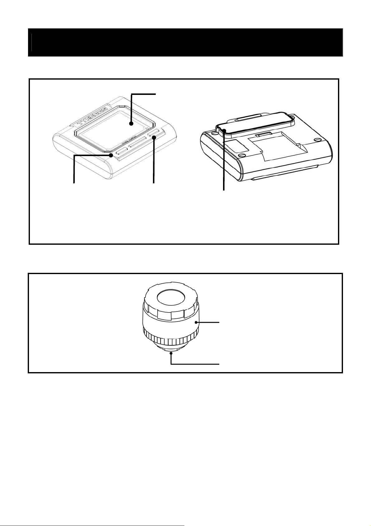
Location of controls and outlook
Monitor description
.LCD monitor
.Temperature.
.Power switch
Front of monitor Back of monitor
Sensor description
.Backlight
.SET
.Battery cover
Sensor battery cover
Valve stem connection
8
V1.01-FJ04 (1105068)
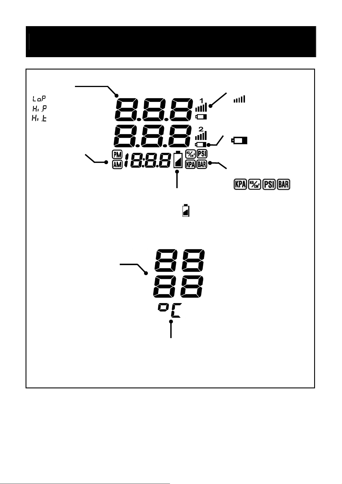
Graphic User Interface and Contents
(
T
y
Tire Pressure
Tire Status:
Low Pressure
High Pressure
High Temperature
Time Display
Connection Status:
: Data Received
No icon):Data Not Received
Sensor Power Status:
: Low Battery
(No icon): Normal
Pressure Measuring Unit:
Tire Temperature:°C / °F
Monitor Power Status:
: Low Batter
(No icon): Normal
emperature Measuring Unit:°C / °F
9
V1.01-FJ04 (1105068)
System map
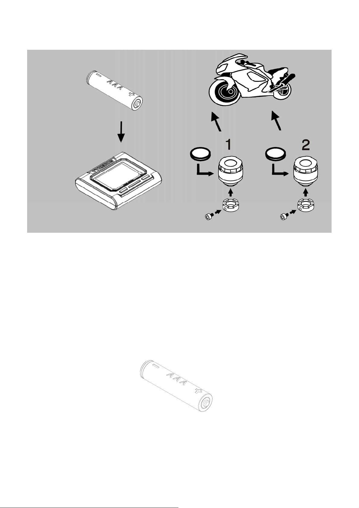
Installation
The installation of LCD monitor
Insert battery:
A. Prepare one AAA-type battery.
10
V1.01-FJ04 (1105068)
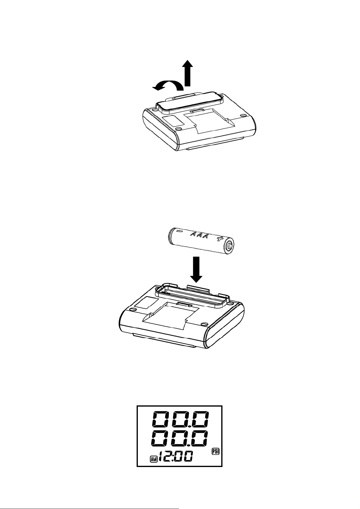
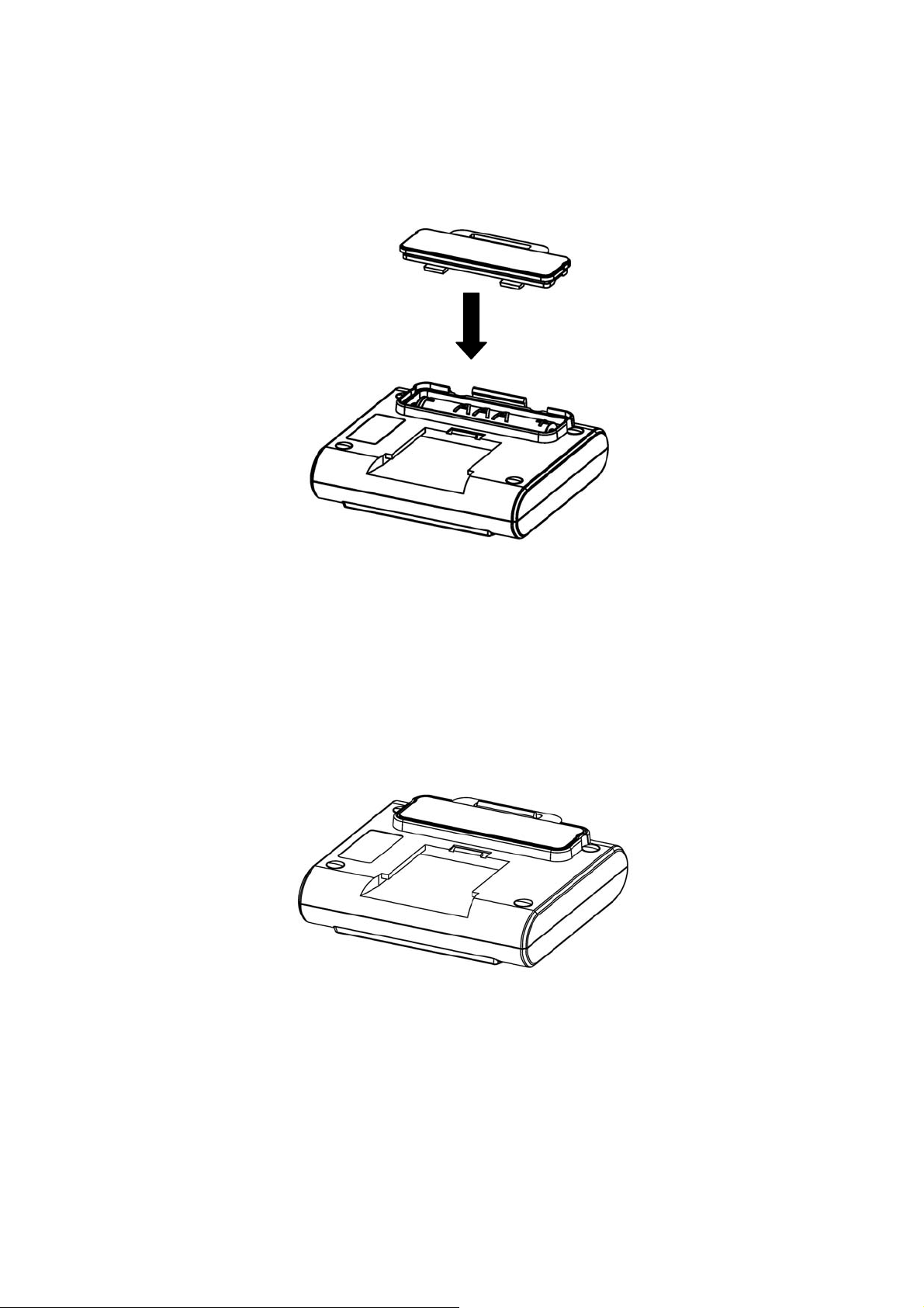
B. Place finger tips near convex bottom edge and open the
battery cover.
1
2
C. Install battery, please follow battery compartment battery
direction icon.
D. After battery inserted, the LCD monitor will automatically
power on and the display will show graphics as picture below.
11
V1.01-FJ04 (1105068)
E. Please be careful with the battery cover hook and a void
damage the hooking.
F. Please carefully aligned, and press the battery cover mak e
sure the hook is in the slot to avoid water leakage around the
battery compartment.
Caution:
Before installation, make sure the battery waterproof gasket is in
place prohibit to use any sharp object to pick the gasket hook to
avoid damage.
12
V1.01-FJ04 (1105068)
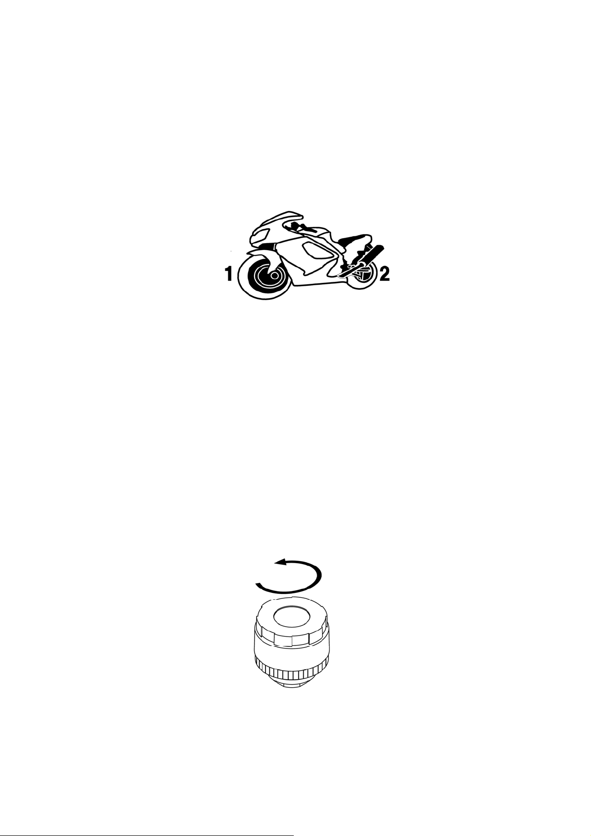
The installation of tire pressure sensors
As sensor has its own position, you have to make sur e its defined
position. When inserting batteries in every sensors please don’t
mix up sensor caps. Sensor map could give guidance for user to
install.
Sensor map
Number 1 means front tire.
Number 2 means rear tire.
Insert batteries in sensors:
Battery installation for tire pressure sensor
A. Take away sensor cap in anti-clockwise direction.
13
V1.01-FJ04 (1105068)
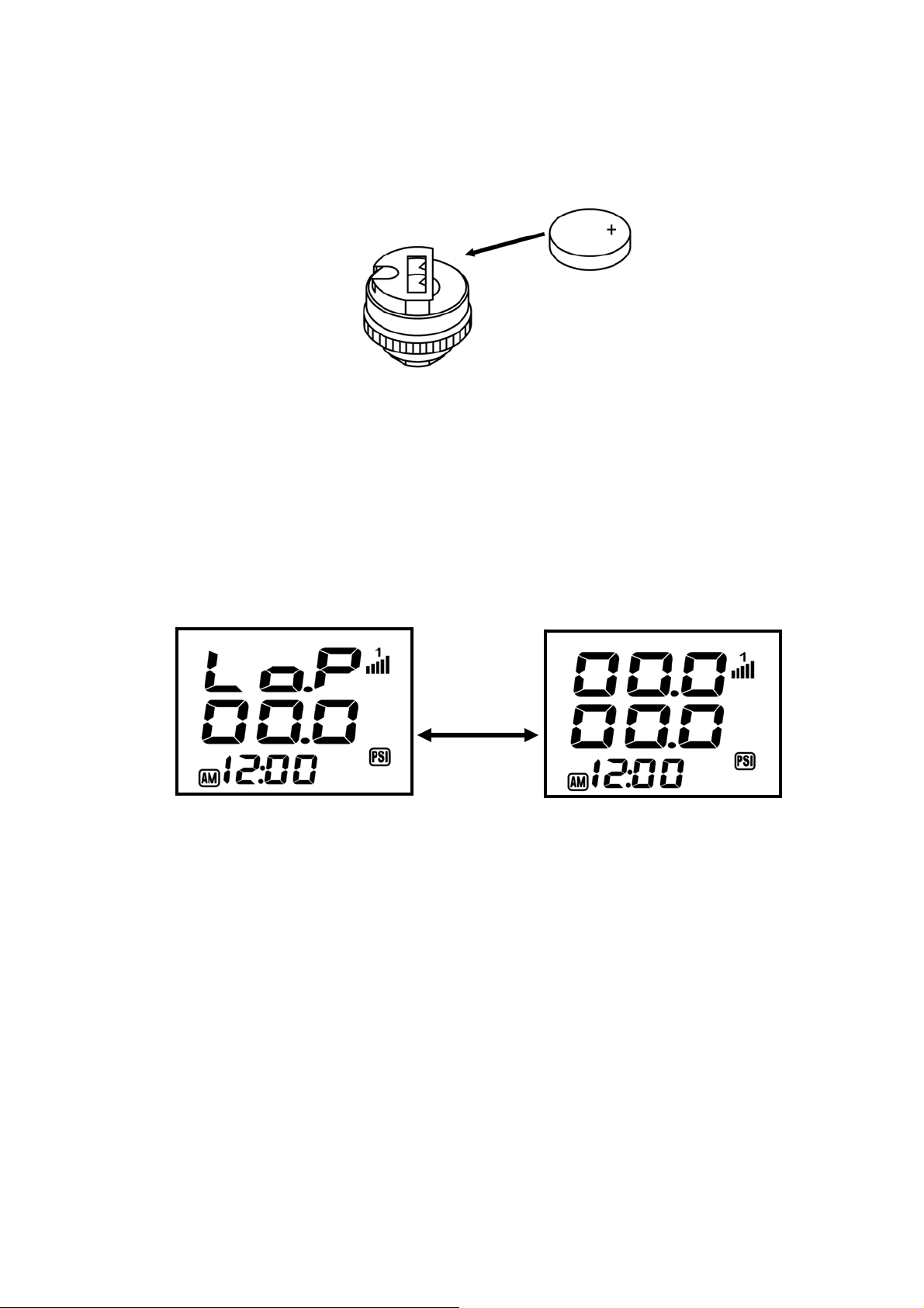
B. Insert lithium battery and make sure battery polarity correct
when insert it.
Right now, monitor will receive signals from corresponding
sensors and report pressure value on the screen. At first, you will
f ind that the value shows “00.0”. It is because sensors have not
been mounted yet. The screen could show as below.
Blinking
Take number 1 for example
Note:After take away battery , the status of being without battery
need to leave for 10 seconds and then insert battery again.
It is for resetting system.
14
V1.01-FJ04 (1105068)

C. Fit sensor cap in a clockwise direction.
Please refer to “sensor map” to make sure the right position of
each sensor and please don’t mix up sensor caps either. You will
find either sensor cap and sensor body have marks to remind
user of its position.
Take number 1 for example
Anti –theft tool for sensor (optional)
Anti –theft tool is designed to prevent the possibility of sensors
being taken away. Users can decide if it is needed or not.
15
V1.01-FJ04 (1105068)

Sensor
Anti-theft fixed ring
Hex socket Screw
Valve
A. Put anti-theft fixed ring onto valve stem.
(Before installed sensor, please make sure the valve stem is
properly clean, so there is no affect during tire pressure
measurements.)
B. Install sensors onto valve stem. Don’t install sensors by brute
force.
16
V1.01-FJ04 (1105068)

C. Now, the display will show you the latest valve of tire
pressure.
Take number 1 for example
D. Adjust the anti-theft fixed ring position to install it with sensor
in place firmly.
E. Put the hex socket screw onto the anti-theft fixed ring.
(Please don’t exert excessively to damage the valve.)
17
V1.01-FJ04 (1105068)

F. When two tire pressure sensors are installed, please check
with soap water if the tire pressure sensors and tire valve is
completely fitted without any air leakage.
(spread soap water on the valve stem)
G. The anti-theft tool can be decided to install or not. If not, step
A, C and D could be just skipped.
18
V1.01-FJ04 (1105068)

Install monitor to the handle bar bracket
Two combinations of a fixed bracket.
Method A:This method can directly assemble the bracke t on the
Brake Fluid Reservoir.
Step 1. Place the ball shape fastener into the Y shape clamping
until hear click sound.
Step 2. Install the adjustable holder screw and adjust with a
slotted screwdriver to appropriate screw tension.
Method A Figure
19
V1.01-FJ04 (1105068)

Remove the original screw from Brake Fluid Reservoir and align
bracket, then install the screw back Please use proper force
tighten the screw.
Method B:This method may be locking with method A on a
variety of handle bar dia meters.
Step 1. Make sure the handle bar diameter to be locking, and a
corresponding diameter of the anti slip holder mounting
plate placed in the handle bar.
Step 2. Install the bracket to the handler bar and properly tighten
the screw.
20
V1.01-FJ04 (1105068)

Method B Figure:
Upright to the handle Parallel
The anti slip pad can be fixed in three sizes
1. Handle bar diameter 1 1/8〞(28mm)
2. Handle bar diameter 1 〞(25mm)
3. Handle bar diameter 7/8〞(22mm)
Install monitor on the bracket
Parallel to the handle bar (front)
Parallel to the handle bar (rear)
Make sure the monitor is properly click with the holder.
21
V1.01-FJ04 (1105068)

Caution:
1. Recommend not to use other screw f or replacement of original
screw to prevent damage.
2. Do not over force tighten the holder screw to av oid damage on
the Y shape bracket.
3. Strongly suggest use the silicon cover for extra protection.
4. If the silicon cover is wet, please dry with nature air before
use.
22
V1.01-FJ04 (1105068)

Operation instructions
/
g
T
Monitor basic function
Locations and function buttons
Basic function
Power Switch
Backli
Set: pressure unit setting
Learning mode
emperature
Power switch: on
ht
temperature unit setting
pressure warning value setting
temperature warning value setting
off
Press once
Power on LCD monitor
Press for over 3 seconds
Power off LCD monitor
23
V1.01-FJ04 (1105068)

Display tire temperature figures
Push this button, the LCD monitor will display tire temper ature instead
of tire pressure.
Display tire temperature
Backlight: on/ off
When in darkness, you also can check out tire pressure and
temperature by pressing backlight button. The backlight will be off
after 15 seconds.
24
V1.01-FJ04 (1105068)

Advanced setting mode
Three
Seconds
Pressure unit setting
Temperature unit setting
Pressure warning value setting
Temperature warning value
Press “ Backlight button” for over 3 seconds to enter advanced
setting mode. Make choice by pressing “Backlight button” and can
adjust warning values.
25
V1.01-FJ04 (1105068)

A. Set pressure measuring unit:
Four types of pressure measuring units: PSI,KPA,BAR and ㎏/㎝
2
are provided here. Users can make their own choices by
“Temperature button”.
B. Set temperature measuring unit: ℃ and ℉
Two types of temperature measuring units: ℃ and ℉
are provided
here. Users can make their own choices by “Temperature
button”.
26
V1.01-FJ04 (1105068)

C. Setting front wheel lower pressure warning value:
Setting front wheel lower pressure warning value, adjust setting
with flush icon. Press temperature button and bac klight button f or
adjustment .The default value is 26 PSI.
Blinking
D. Setting front wheel upper pressure warning value
Setting front wheel upper pressure warning value,adjust setting
with flush icon。Press “Temperature button” for adjustment. The
default value is 45 PSI.
Blinking
27
V1.01-FJ04 (1105068)

E. Set front wheel temperature upper warning value
g
The default value is 70 ℃ and users can make their own choices by
“Temperature button”.
Blinkin
F. Setting rear wheel lower pressure warning value
Setting rear wheel lower pressure warning value, adjust setting
with flush icon. Press for “Temperature button” adjustment.
Blinking
28
V1.01-FJ04 (1105068)

G. Setting rear wheel upper pressure warning value
Setting rear wheel upper pressure warning value, adjust setting
with flush icon. Press “Temperature button” for adjustment.
Blinking
H. Set up rear high temperature when the icons flush. The factory
setting is 70 ℃, press “Temperature button” for adjustment.
Blinking
29
V1.01-FJ04 (1105068)

I. Set up monitor time value, adjust setting with flush icon. Press
“Temperature button” for adjustment.
Blinking
Blinking
Note:When battery inserted, time value will be resetting, so you can
adjust time again after battery inserting.
This mode will return to main screen as long as there is no
operation for more than 25 seconds.
30
V1.01-FJ04 (1105068)

Sensor learning mode
Five
Seconds
In a very unlike case, sensor could be broken or missed. Sensor
learning mode can provide an alternative way to replace sensors with
‘learnable sensors’. (‘Learnable sensor’ will need to purchase
separately.) LCD monitor can reload new identif ied number only from
‘learnable sensor.’ By obtaining new identified number from new
‘learnable sensor’, the system will integrate this sensor into its system
and replace old one.
Pressing “Backlight button” for around 5 seconds, the system will
enter ‘learning mode’, and system will start to recognize new sensors.
As long as enter this mode, insert battery into ‘learnable sensor’
immediately, the LCD monitor will beep once and finish learning
process.
Take number 1 for example
The ‘learning mode’ will continue for about 30 seconds and then back
to main screen.
31
V1.01-FJ04 (1105068)

Operation instructions
1. Main screen
Switch on LCD monitor to boot up, and LCD monitor will be
communicating with sensors and showing tire pressure values that
is kept from last time before system was off. In this mode, you will
find the time icon will be showing.
2. Automatically power off
For power saving purpose, very intelligent design in this system
could automatically enter sleeping mode as long as the monitor has
not been vibrated for more than 20 minutes. In this mode, monitor
will be turn off to save battery power.
When no vibration
for over 20 minutes
(No icon)
Restart the monitor from sleeping mode press any button, or vibration
can trigger the restart function, for example wheel movement, etc. At
the same time monitor will display all 2 tire data.
32
V1.01-FJ04 (1105068)

3. Abnormal status
A. Tire pressure below lower warning value
When tire pressure is below lower warning value (default value=
26 PSI), LCD will appear icon blinks. Push any button,
then the LED warnings will be disable.
Blinking
Take number 1 for example
B. Tire pressure higher than upper warning value
When tire pressure is higher than upper warning value, (default
value= 45 PSI), LCD will appear icon blinks. Push any
button, then the LED warnings will be disable.
Blinking
Take number 1 for example
C. Tire temperature higher than upper warning value
When tire temperature is higher than upper warning value,
33
V1.01-FJ04 (1105068)

(default value= 70℃), LCD will appear icon blinks. Push
any button, then the LED warnings will be disable.
Blinking
Take number 1 for example
D. LCD monitor runs out to power
Battery power in monitor will decrease by daily operation and
when power level is lower to some extent, the monitor battery
low indicator will appear to remind rider of time to replace
battery. The icon is shown as picture below.
E. Tire pressure sensor runs out of power
Battery power in sensor will decrease by daily operation and
when power level is lower to some extent, the sensor battery low
indicator will appear to remind driver of time to replace battery.
34
V1.01-FJ04 (1105068)

The icon is shown as picture below.
Take number 1 for example
35
V1.01-FJ04 (1105068)

The definition of warnings
Item Status Purpose Pattern
1. Tire pressure is below
lower warning range.
2. When tire pressure is
below lower warning
range, each 1 PSI
down, warnings will be
given as well.
3. Tire pressure is higher
than upper warning
range.
The warning of low
tire pressure.
The warning of tire
pressure getting
lower.
The warning of high
tire pressure.
LCD will appear
icon blinks.
Push any button, then the
LED warnings will be
disable.
LCD will appear
icon blinks.
Push any button, then the
LED warnings will be
disable.
LCD will appear
icon blinks.
Push any button, then the
4. When tire pressure is
higher than upper
warning range, each 1
PSI up, warnings will be
given as well.
5. Tire temperature is
higher than upper
warning value.
The warning of tire
pressure getting
high
The warning of high
tire temperature.
LED warnings will be
disable.
LCD will appear
icon blinks.
Push any button, then the
LED warnings will be
disable.
LCD will appear
icon blinks.
Push any button, then the
LED warnings will be
disable.
36
V1.01-FJ04 (1105068)

6. When ire temperature is
The warning of tire
LCD will appear
higher than upper
warning range, each 1
PSI up, warnings will be
given as well.
7. Learnable sensor is
integrated.
temperature getting
high.
Finish learning
mode.
icon blinks.
Push any button, then the
LED warnings will be
disable.
LED warnings alert
once.
37
V1.01-FJ04 (1105068)

Troubleshooting
The following checklist will help you remedy problems you may
encounter with your unit. Before going through the checklist below,
check the connection and operating procedures.
1. Indications disappear from / do not appear in the display.
A. Please make sure if power switch is on.
B. Please make sure if monitor has battery inserted.
C. Be sure the power of battery is enough.
D. Be sure to observe the correct polarity when installing the
batteries.
E. If these solutions do not help improve the situation, consult your
nearest Tyredog dealer.
2. No connection between sensors and monitor.
A. Please make sure if sensor has battery (CR1632) inserted.
B. Be sure to observe the correct polarity when installing sensor
batteries.
C. Bat t ery could run out of power and we suggest to replace with
new battery.
D. If these solutions do not help improve the situation, consult your
nearest Tyredog dealer.
3. Monitor display color is getting dark.
When monitor temperature is over 80 , it is natural that LCD panel ℃
will be getting dark. When monitor temperature is back to normal,
LCD panel will be normal again.
38
V1.01-FJ04 (1105068)

4. When temperature is below -20 , the response time℃ of CD
monitor could be slower.
5. ‘Learning mode’ can only accept ‘learnable sensor’ but not standard
sensor.
39
V1.01-FJ04 (1105068)

Additional Information
Under normal conditions, sensor batteries will last approximately 1~2
years. LCD monitor will last around 6 months. (The service life may be
shorter, depending on the conditions of use.) When the battery becomes
weak, the power low indicator will appear on the screen. Replace the
battery with a new CR1632 lithium battery for sensor or with AAA 1.5
battery for LCD monitor.
Notes on battery
Keep the battery out of the reach of children. Should the bat t ery be
swallowed, immediately consult a doctor.
Wipe the battery with dry cloth to assure a good contact.
Be sure to observe the correct polarity when inst alling the battery.
Do not hold the battery with metallic tweezers, otherwise a
short-circuit may occur.
Battery may explode if mistreated.
Don’t recharge, disassemble, or dispose of in fire.
40
V1.01-FJ04 (1105068)

Adj
Package content
Here are items in whole package.
Item Photo number
TD4100A-X
LCD monitor
Ball shape turning
fastener
Y shape clamping
1 pieces
1 pieces
1 pieces
ustable screw
for holder
1 pieces
Handle bar bracket
1 pair
41
V1.01-FJ04 (1105068)

1 1/8〞Handle bar
anti slip gasket
7/8〞Handle bar anti
slip gasket
1〞Handle bar anti
slip gasket
1 pair
1 pair
Screw for handle
bar bracket
Silicon cover
1 pair
2 pieces
1 pieces
42
V1.01-FJ04 (1105068)

TD4100A-X
tire pressure sensor
CR1632 battery
Anti-theft tool
User guide
2 pieces
Spanner 1 piece
2 pieces
Anti-theft
2 pieces
fixed ring
Hex socket
2 pieces
screw
1 piece
AAA 1.5V battery
1 piece
43
V1.01-FJ04 (1105068)

Product Specifications
Tire pressure sensor specifications
Frequency 433.92MHz
Tire pressure range 0 ~ 60PSI
Accuracy Tire pressure ±1 PSI / tire temperature ±2 ℃
Operating voltage 3V DC
Operating
-40℃~125℃
temperature
Battery life 1~2 years (depends on working hours per day)
Dimensions Diameter 20.5mm X height 20mm
Weight 10±1 g
LCD monitor specifications
Frequency 433.92MHz
Operating voltage 1.5V DC
Battery life 6 months (depends on working hours per day)
Operating
-20℃~80℃
temperature
Dimensions Length 68mm X width 62mm X height 16mm
Weight 58g
44
V1.01-FJ04 (1105068)
 Loading...