


- BLANK -

INDEX
IMPORTANT INFORMATION ................................................................3
TPMS ADVANTAGES .......................................................................4
FEATURES ........................................................................................5
ITEM DESCRIPTIONS ........................................................................8
MONITOR DESCRIPTION ...................................................................8
RELAY DESCRIPTION ........................................................................9
MONITOR BRACKET DESCRIPTION ...................................................9
3-WAY ADAPTER DESCRIPTION ........................................................9
SENSOR DESCRIPTION ...................................................................10
GRAPHIC USER INTERFACE (GUI) ....................................................10
GETTING STARTED ..........................................................................11
INSTALLATION .................................................................................11
INSTALLING THE RELAY ...............................................................11
INSTALLING THE MONITOR ..........................................................15
INSTALLING THE SENSORS ..........................................................18
MONITOR SWITCH & BUTTONS .......................................................21
POWER SWITCH .............................................................................21
MUTE BUTTON .............................................................................22
TEMPERATURE BUTTON ...............................................................22
BACKLIGHT BUTTON ......................................................................23
TPMS SETTINGS MENU .....................................................................24
UNIT SETTINGS ..............................................................................25
THRESHOLD SETTINGS ...................................................................26
1
TD-2300A Series V1.0

INDEX Continued..
TYPE OF VEHICLE (WHEEL LAYOUTS) .............................................28
ADD NEW RELAY (RESET) .............................................................31
ADD NEW SENSOR ........................................................................33
HOW TO USE YOUR TPMS SYSTEM ..................................................36
TROUBLE SHOOTING .......................................................................41
PACKAGE CONTENTS - MONITOR .....................................................46
PACKAGE CONTENTS - RELAY .........................................................47
SPECIFICATIONS ..............................................................................49
WARRANTY INFO .............................................................................51
2
TD-2300A Series V1.0

Important Information
This product is designed to indicate the conditions of the air inside your
vehicle’s tyres. It should not be considered as a device that will prevent
any traffic accident, injury or death.
Tyres and valve stems must be checked before installation. It is very
common for rubber valve stems to require replacement without showing
signs of wear. We recommend use on Metal type Valve Stems.
Never overload your vehicle. Overloading is extremely dangerous and
can cause failure of tyres, suspension and driveline components.A
vehicle should never be operated if the GVM is greater than the design
specification. Even a correctly inflated tyre can fail when overloaded.
It is the driver’s responsibility to ensure safe driving conditions are met
before setting off on any trip or journey.
3
TD-2300A Series V1.0

TPMS Advantages
:
A Tyre Pressure Monitoring System (TPMS) is an efficient and effective
solution to many current automotive safety issues. TPMS will help
minimise driving risks and reduce fuel consumption. Some benefits include
z
Ensures safe driving conditions.
Tyre pressures can alter ride comfort and handling response.
z
Minimises chances of tyre blowout.
Blowouts are a growing cause of road accidents. Even if a car can recover
from a blowout, the damaged tyre left behind is an even greater hazard.
z
Reduces time taken to inspect tyres.
It can be very time consuming to walk around large vehicles to inspect
each tyre. A TPMS will help pinpoint a faulty tyre to save time. Everybody
from driving enthusiasts, to small business owners, even nation-wide fleet
operators can benefit from the time saved by a TPMS.
z
Reduces running costs.
A properly inflated tyre ensures maximum fuel efficiency in all driving
conditions. When a tyre is underinflated, it causes more rolling resistance,
significantly increasing fuel consumption, engine and transmission wear.
z
Extends tyre life
Tyres can be an expensive necessity especially in trucks or sports cars. An
underinflated tyre wears quicker meaning it needs replacing sooner.
4
TD-2300A Series V1.0

Exclusive Features
T
T
A
T
T
YREDOG is a powerful tool for maximising uptime and improving safety.
YREDOG sets a new standard in wireless tyre pressure monitoring systems.
leading WTPMS solution for the light to heavy-duty car and trucking
industries, TYREDOG is continuously developing new and better TPMS designs
and manufacturing technologies. TYREDOG has helped major players in the
trucking industry improve safety and reduce operational costs. The major
feature of TYREDOG TPMS is the use of the world’s smallest valve cap sensor.
he extremely lightweight, compact sensor has been designed to simplify
installation and remove the need to have wheels balanced when fitted.
hrough wireless technology, tyre pressure and temperature information is
displayed on the friendly Graphic User Interface (LCD monitor).
Installation
z
D.I.Y: System can be fitted quickly without any technical knowledge.
z
Wireless: All signals are sent via radio frequency with no wires.
z
Battery powered: Sensors, monitor*and relay are battery powered.
Monitor and relay can be operated with supplied power cables.
z
Security: All kits include the SecureFit locking mechanism meaning
your sensors will not come loose unexpectedly.
z
Relay: Increases the signal transmission range, meaning tyres can be
monitored on the largest and most complex vehicles.
* Refer to page #8.
5
TD-2300A Series V1.0

Exclusive Features continued..
Operation
z
Real-time: Tyre pressures are updated automatically so there is no
need to push buttons to check up on your tyres (except temperature).
z
Graphical user interface (GUI): All information is displayed
together so unlike other systems, there is no need to scroll through
eachwheeltoviewstatus.
z
Adjustable: High and low warning alarms can be set ‘per axle.’
z
Audible: You can’t be expected to always keep watch of your tyres, so
a built in alarm will sound when there is a sudden change in pressure
or temperature, giving you peace of mind.
Design
z
All sensors can be securely locked onto tyre valves for added safety.
z
Learnable sensors are available so in the event of theft or damage,
sensors can be quickly and easily replaced.
z
Sensors have unique individual codes to ensure there is no interference
from other 433MHz devices, even other TYREDOG systems.
z
All TYREDOG kits undergo strict field testing to ensure quality.
z
The TD-23 00A-X can monitor tyres with pressures up to 180psi so all
applications are supported.
z
Sensors are treated for anti-corrosion during manufacture and use
rubber seals to prevent liquid and fine particles from coming in contact
with the circuitry.
6
TD-2300A Series V1.0

Tyre Pressure & Safety Information
x Please take the time to choose a suitable location so operation can be
performed quickly and safely.
o Be sure that the LCD monitor is firmly fixed to the windshield or
dashboard using the supplied mounting hardware.
o Please practice safe driving and only take the time necessary to
read the information displayed on the screen.
x Ensure the sensors communicate with the LCD monitor before initially
fitting them to your tyres to save time and hassle.
x Tyredog TPMS has a unique SecureFit mechanism to prevent sensors
from coming loose. You can decide whether to install it or not.
x Regularly check if sensors are fitted tightly. If necessary, spread water
with detergent on the valve stem to see if your valves are leaking.
x If a rapid deflation warning sounds, stop the car immediately to check
the tyre for damage. Remember to be safe when pulling over.
x The monitor will automatically make connections when it is powered on.
x Many factors can cause tyre pressure to rise and fall. For example, warm
weather or long distance trips will lead to a rise in tyre pressure.
x It is normal for tyre pressure to decrease over long periods of time.
Periodically re-inflate tyres especially if your car is not regularly driven.
x If you have any questions or problems concerning your unit that are not
covered in this manual, please consult your nearest Tyredog dealer.
7
TD-2300A Series V1.0
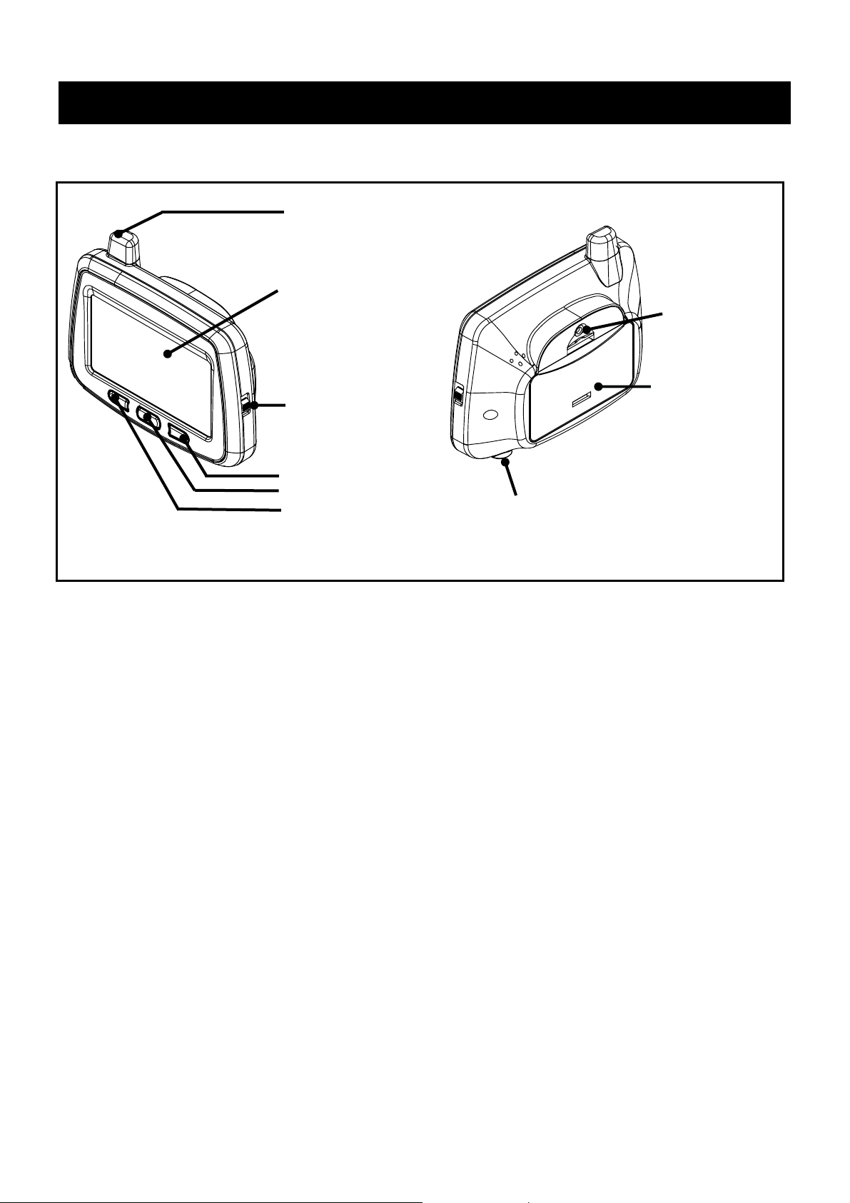
Item Descriptions
Monitor description
Antenna
LCD Monitor
Power Switch
Backlight
Temperature
Mute
Front of Monitor
12/24VDC Input
(Cigarette Lighter Adaptor)
Back of Monitor
Screw hole
for bracket
Battery Cover
Important Note: The TD-2300A monitor has not been designed to work
with Batteries and will only work using the cigarette lighter adaptor.
However for testing, programming and trouble shooting purposes you
can insert 2 x AA batteries.
8
TD-2300A Series V1.0
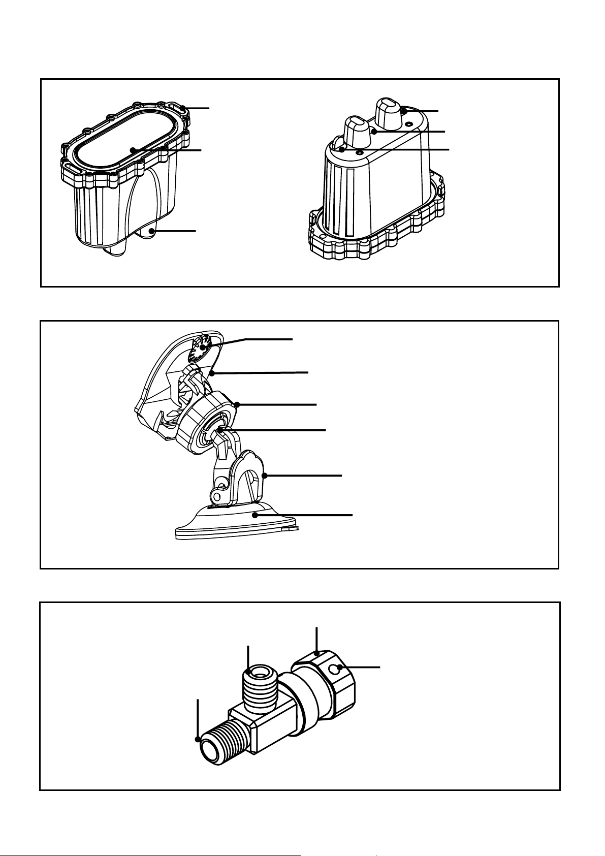
Relay description
y
A
Mounting holes
Batter
ntenna
Top
Monitor bracket description
cover
Sync Button
LED
DC Socket
Bottom
Set screw
Monitor holder
3-way adapter description
Connection to Sensor
Inflation valve
Fixed lock ring
Holder arm base
Suction cup control arm
Bracket stand
Monitor Bracket
Connection to valve
Hex socket set screw
(The 3-way adapter is not included. Please purchase it separately. )
9
TD-2300A Series V1.0
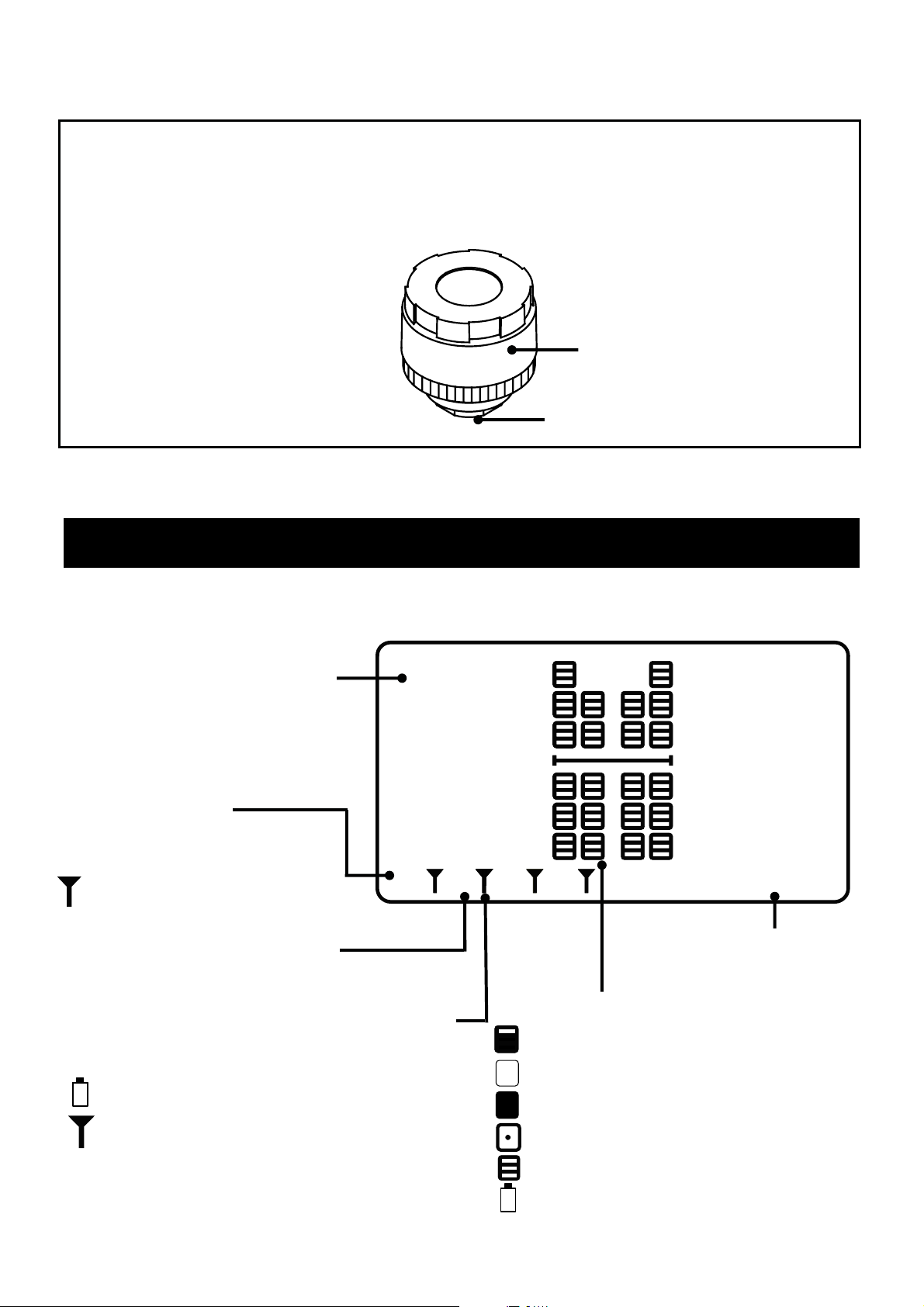
Sensor Description
T
he sensor has two sections: The sensor cap and sensor body. Its lightweight
design and external application is intended to aid D.I.Y. installation.
Battery Cover
Valve stem connection
GUI Layout / Icons
Tyre pressure or temperature
128
128
128
Monitor Status(When 3 x relays)
H:Head page
T:Trailer page
128
128
128
:Receiver working ok
Relay Position
A:Truck B:Trailer 1 C:Trailer 2
Relay battery power & Connection status
X : No connection to monitor
:Low Battery / Relay
:Relay connected to Montior
128
128
128
128
128
A
BH
Tyre status
Normal
Under Inflated
Over inflated
High Temperature
C
128
128
128
128
128
128
Tyre pressure or
Temperature measuring unit
128
128
128
128128
128
PSI
Sensors is Offline
Low Battery in Sensor
10
TD-2300A Series V1.0
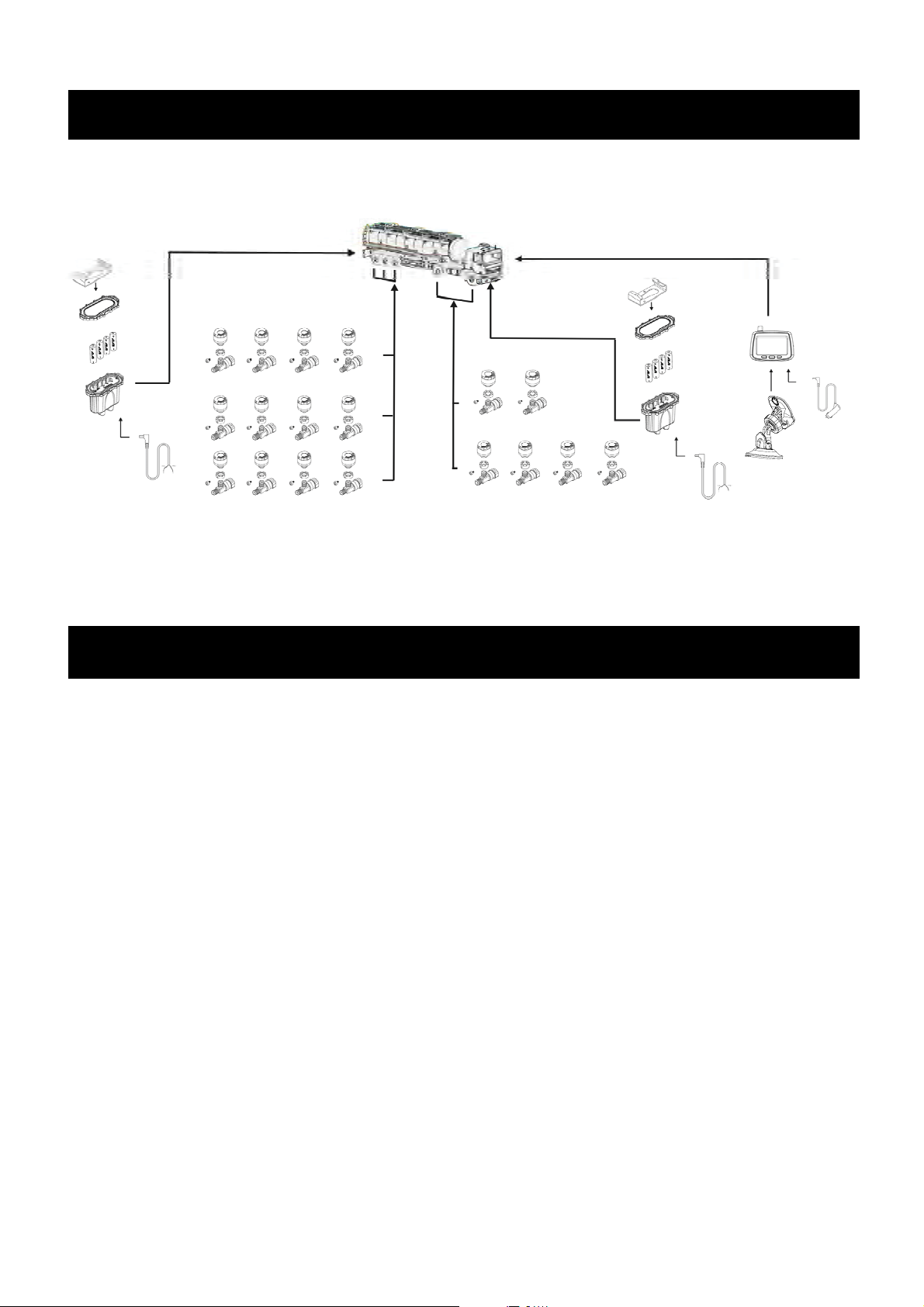
Getting Started
Example Diagram.
Note:The 3-way adapter is not included and is for illustrative purposes only.
Installation - RELAY
The relay is the main link between the sensors and the monitor. Without it,
the system will not function. It is recommended the relay be mounted in a
central location with considerably even distance between the furthest forward
and furthest rearward sensors.
It is important to remember that sensors connect to the relay they are
assigned to. If the relay is removed from the vehicle, the system will not
function. This is vital in Truck/Trailer (Car/Trailer) situations when the trailer is
often unhitched from the main vehicle. The relay should be mounted at the
rear of the vehicle in this case to ensure optimum performance.
11
TD-2300A Series V1.0
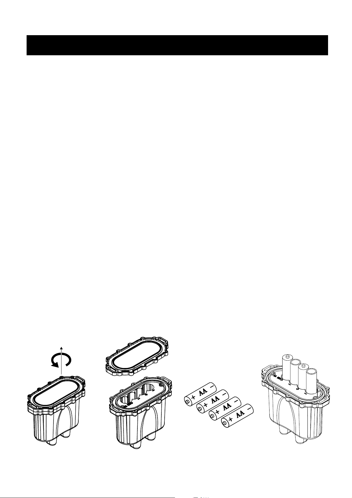
Installation - RELAY
The relay can either be powered by 4 x AA batteries or it can be hardwired
using the cable supplied.
TIP: If using the hardwired power cable, we recommend that you connect to a
permanent 12V/24V supply to ensure correct functionality of the relay.
Connecting to a switched power source such as accessories or ignition, may
cause synchronization issues with the monitor when powered up.
BATTERY POWER
To open the battery cover, undo the 12 Philips head screws. Insert the
supplied AA batteries into the battery slot observing the polarity markings.
When refitting the battery cover, be sure to line up the contact springs
correctly and ensure they are not bent upon contact.
Note: Inserting the battery incorrectly will cause damage to the relay.
Replace the 12 screws removed previously and ensure the rubber o-ring is
properly seated prior to tightening.
12
TD-2300A Series V1.0
(
)
(
)
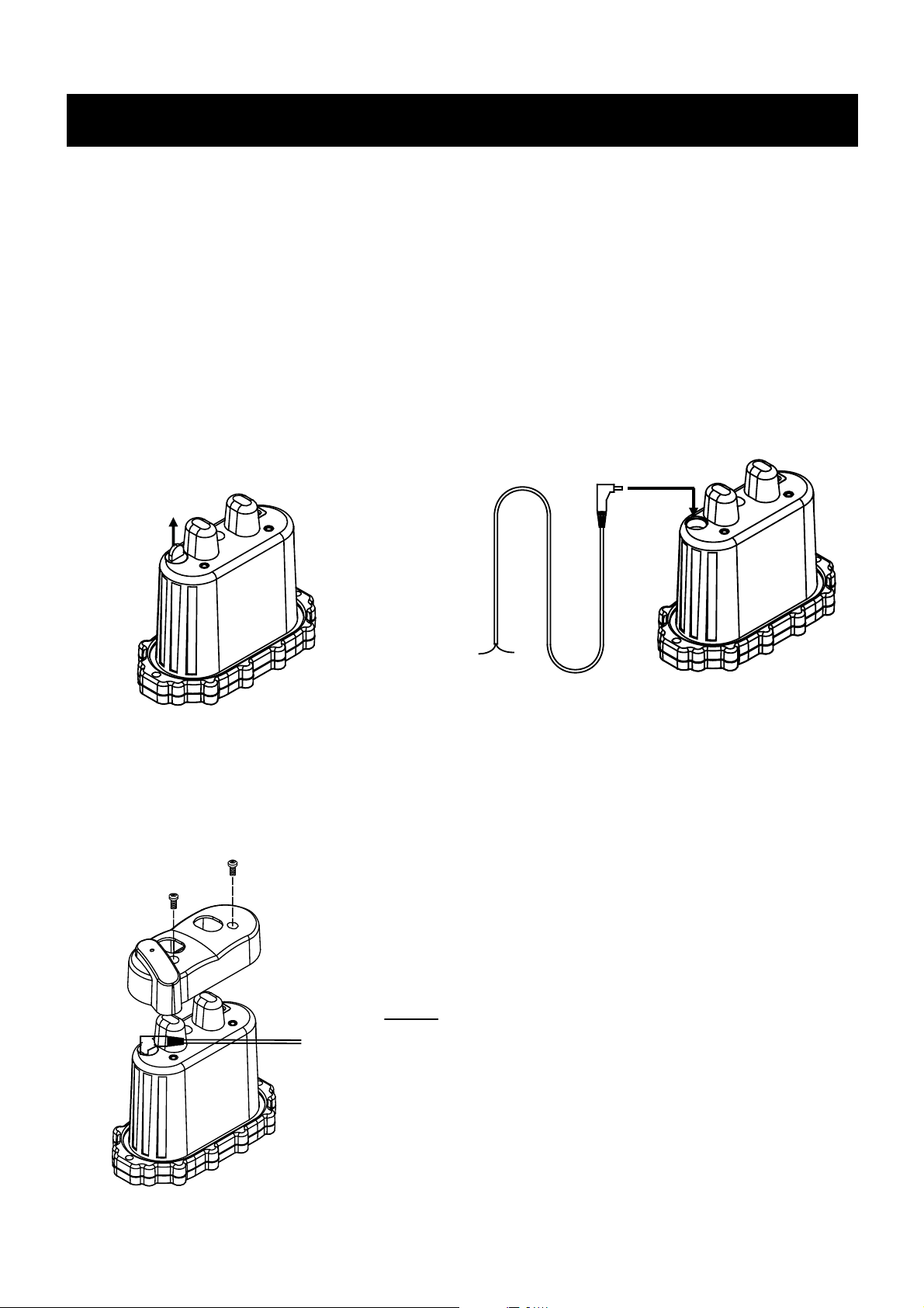
Installation - RELAY Continued..
HARDWIRED (12V/24V)
If using the included power cord, remove the DC socket plug at the bottom of
the relay. (If not using the power cord, ensure this socket plug remains fitted
as it seals the Relay from water etc.) When plugging in the DC plug, ensure it
is plugged in firmly so it will not come loose. When inserted correctly, it will be
sealed from water and other elements.
Remove Plug
-
+
White
To esnure the relay is protected, we strongly recommend that the Red (+) wire is fused
protected. We Recommend adding an inline 3A fuse.
Red
If the relay is hardwired, please ensure there are no batteries fitted to the Relay.
When using the power cord, the supplied bottom
cover must be fitted to ensure the D.C. plug does
not come loose.
13
TD-2300A Series V1.0

Installation - Mounting the Relay
A
,
T
When fitting the Relay, time and care must be taken to properly decide on a
mounting location. Some key factors that must be considered are:
x The Relay must be mounted outside the vehicle. (not under bonnet)
x Total distance between first and last sensors.
x Total distance of car, truck, car + trailer etc.
x Vehicle/trailer structure (chassis/body density etc)
Please remember that any metal between the sensors/relay/monitor may play
a part in limiting the signal transmission between Tyredog components.
lthough a metal object may not be in the direct line of sight between the
components, it may still hinder signal transfer if the object is nearby or offside
to the signal transmission path.
When mounting the Relay, be sure that it is mounted away from moving parts
(tail shaft, axle, etc.) sources of heat (exhaust) and is fitted in such a place
that would keep it protected from potentially damaging terrain.
he Relay should be mounted using the supplied heavy duty bracket and an
existing bolt like shown in the diagram below.
Drilling holes into a vehicle’s body/chassis is not recommended as this may
affect the structure and your vehicles Warranty.
Car/Truck body
B
A
Car/Truck body
Once the bracket is firmly mounted to the Car/Truck body, the relay can be
mounted to the bracket with the supplied screws and washers.
14
TD-2300A Series V1.0
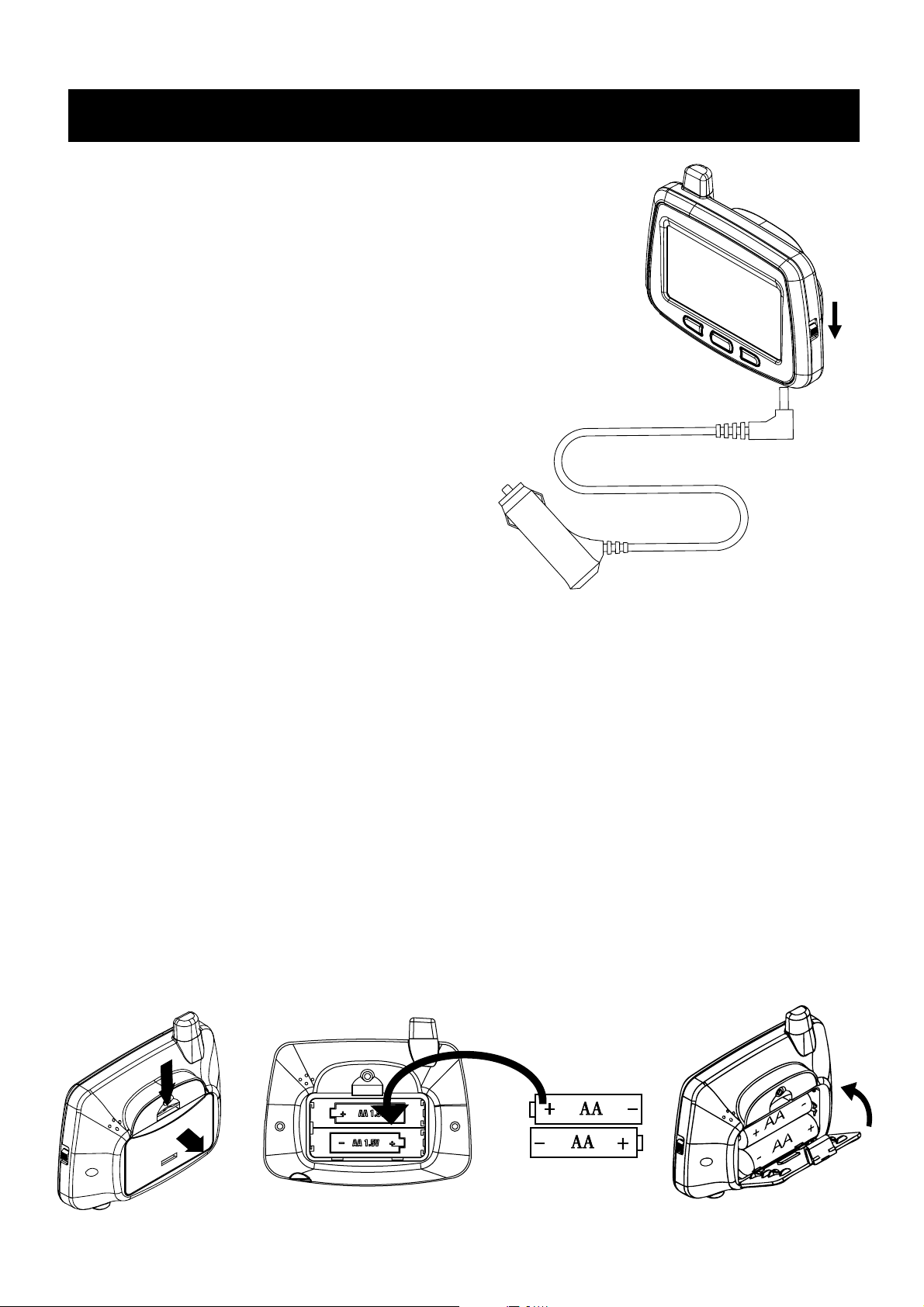
Installation - Monitor / Receiver
The TD-2300A Monitor must be powered up
using the cigarette lighter adaptor supplied.
Simply plug the power cord into the monitor like
shown then connect the cigarette lighter plug to
a D.C. Outlet Socket in the vehicle.
12V / 24V DC
BATTERY POWER
The TD-2300A Monitor has a provision for 2 x AA Batteries which can be
inserted for Trouble Shooting and Testing Purposes Only. When the Moni-
tor is using Battery Power, the Monitor will automatically turn off after 60
seconds. Once the monitor turns off, you can press any button and it will
turn back on for a further 60 Seconds.
Battery Power can be used for setting the warning thresholds, program-
ming new relays, sensors etc..
Before reconnecting the monitor to hardwire (Cigarette Lighter Plug), we
recommend removing the AA Batteries from the Monitor.
A
B
15
TD-2300A Series V1.0

Installation - Monitor / Receiver Bracket
Monitor
Bracket Screw
Bracket Adaptor
Ball Joint Ring
Ball Joint
Suction Cup Lock
Suction Cup
Monitor Bracket
1. Slide the Ball joint ring over the Ball Joint.
2. Insert the Ball Joint into the Bracket Adaptor. Your will here it ‘Pop In’.
3. Screw the Ball Joint Ring onto the Bracket Adaptor until had tight.
16
TD-2300A Series V1.0

Installation - Monitor / Receiver Bracket
4. Place the Monitor Bracket into the Bracket Adaptor clips.
5. Gently push the Monitor Bracket against the adaptor clips and slide
down until the Monitor Bracket locks in place.
6. Now connect the Monitor Bracket to the Monitor and screw it into place.
7. Position the Bracket Suction Cup to a suitable location on the
windscreen ensuring it doesn’t obstruct the view of the driver.
8. Once in position, push down on the base and lower the Suction Cup
Lock to apply suction.
9. You can then adjust the monitor angle and tighten the Ball Joint Ring.
17
TD-2300A Series V1.0

Installation - Sensors
1. Remove the Sensor Cap by rotating the cap anti-clockwise then insert
the 3V Lithium Battery (CR1632) like shown below.
Note: Positive (+) of battery should be facing up.
CR1632
Lithium 3V
+
1
(1)
If the Monitor and Relay are both powered up, as soon as the battery is
inserted into the sensor, you will hear the monitor beep and you’ll see the
sensor come online. It will also be flashing ‘P.L’ and ‘0’. This indicates the
Pressure is Low and it’s reading ‘0’ PSI as the sensor has not been fitted to
a Tyre.
P.L
0
0
0
0
0
2. Once the Sensor comes onlline, re-fit the sensor cap ensuring it’s nice
A
0
0
0
0
0
BH
C
0
0
0
0
0
0
0
0
0
0
0
PSI
and tight so no water will get in. (Don’t use extreme force though as you
don’t want to break or crack the cap)
3. Repeat Steps 1 & 2 with the rest of the sensors ensuring you don’t mix
the sensors and caps up. These are identified with a marking ‘1 to 12’.
18
TD-2300A Series V1.0

Installation - Sensors Continued..
Before fitting the sensors to the wheels, it’s important that you know
where each sensor should go.
The Diagram below shows the layout and sensor positions for the maxi-
mum 34 Wheel setup.
For all other configuarations, start from the top (Front) and go from left to
right.
Example 4 Wheel: Front Left Wheel (1), Front Right Wheel (2), Rear Left
Wheel (3), Rear Right Wheel (4).
Example 6 Wheel: Front Left Wheel (1), Front Right Wheel (2), Rear Left
Outer Wheel (3), Rear Left Inner Wheel (4), Rear Right Inner Wheel (5),
Rear Right Outer Wheel (6).
The Truck (A) Unit can
support up to 10 Wheels
The First Trailer (B) can
support up to 12 Wheels
The Second Trailer (C) can
A1
A3
A7
B1
B5
B9
C1
A4
A8
B2
B6
B10
A BH
C2 C3
A5
A9
B3
B7
B11
C
A2
A6
A10
B4
B8
B12
PSI
C4
support up to 12 Wheels
C6C5
C9
C10
A BT C
19
C7 C8
C
2C1
1
1
PSI
TD-2300A Series V1.0

Installation - Sensors Continued..
Visually inspect your tyre’s valves for any damage or defects before fitting
the sensors to ensure that further damage doesn’t occur. If you do notice
that something is not right with your valves, have them checked by a tyre
professional.
INSTALLATION
1. After removing the original valve caps, slide the SecureFit fixing ring
over the valve stem with the flat surface towards the wheel.
2. Screw the Tyredog sensor on in a clockwise direction until you feel the
valve stem come under pressure.
3. Slide the SecureFit fixing ring back up to the base of the sensor and
line up the grooves. Once locked into place, tighten the hex screw with
the supplied Allen key. (Don’t over tighten otherwise you might damage
your valve stem)
If you do not wish to use the SecureFit fixing ring, only follow step 2.
1.
2.
3.
20
TD-2300A Series V1.0

Monitor Switch & Buttons
p
Button Location and Features
Mute
Tem
erature
Backlight
OFF
Power
ON
Power switch
When the unit is first switched on, the Monitor will show all sensors
offline until it connects to and receives an update from the relay.
128
128
128
128
128
128
128
128
128
128
128
A
BH
C
Display showing all sensors
and relays offline.
128
128
128
128
128
128
128
128
128
128128
128
PSI
128
128
128
128
128
128
128
128
128
128
128
A
BH
C
Display showing all sensors
and relays online.
128
128
128
128
128
128
128
128
128
128128
128
PSI
21
TD-2300A Series V1.0

Monitor Switch & Buttons Continued..
Mute
When the alarm is sounding for low pressure, high pressure or high
temperature, simply press this button once and this will silence /
mute the sound until another warning alarm occurs.
You can also press and hold this button for 3 seconds to get into the
settings menu.(Refer Page 24)
Temperature
Press the Temperature button once and this will display the tem-
perature of each tyre for 10 seconds. (Or push the button again and
it will go back to displaying the Pressure)
25
25
25
25
25
25
25
25
25
25
25
25
25
25
25
25
25
25
25
25
25
25
o
C
Temperature
measuring unit
( / )
o
CoF
22
TD-2300A Series V1.0

Monitor Switch & Buttons Continued..
z Backlight
z Switch between screen views
Press and hold the Backlight button for 3 seconds to turn the Back-
light OFF. Press and hold for 3 seconds to turn it back ON.
128
128
128
128
128
128
Due to the size of the display, the monitor can only display the first 2
Relays on the home screen. (Truck (A) and Trailer 1(B))
If you have a 3 Relay setup, to view the 3rd Relay simply press the
Backlight button once and it will display the Pressure readings.
(Press the Temperature button to view the Temperature while view-
ing the 3rd Relay (Trailer 2(C)) if you want to see the Temperature
128
128
128
128
128
A
BH
C
128
128
128
128
128
128
128
128
128
128128
128
PSI
readings). Press the Temperature Button once again to go back to
the main screen.
Note: If there is a warning alarm, it will automatically display the
affected wheel position / screen view.
128
128
128
128
128
128
128
128
128
128
128
A
BH
C
128
128
128
128
128
128
128
128128
128
128
128
PSI
23
128
128
128
128
128
128
A BT C
128
128
128
TD-2300A Series V1.0
128
128
128
PSI

TPMS Settings Menu
To access the Main Settings Menu, press and hold the Mute Button for 3
seconds or until the Menu Screen appears.
From this Menu you can access the following settings:
MAIN MENU OPTIONS
A) Unit Setting - Pressure (PSI/KPA/BAR/KgCm) - Temperature (°C / °F).
B) Threshold of Alarm - Set Low & High Pressure / High Temperature.
C) Type of Vehicle - Set Wheel Layout for each Relay.
D) Add new Relay (Reset/Synch Relay) - Program New or Reset Relay/s.
E) Add new Sensor - Program replacement LEARNABLE Sensors.
Settings
Settings Menu
A) Unit Setting
B) Threshold of
Alarm
C) Type of
Vehicle
D) Add new
Relay
Mute Temperature Backlight
>>
(Next)
ESC
(Escape) (Select)
>>
(Enter/Save)(Next Option)
(Next Option)
+
(Increase)
(Change)
-
(Decrease)
(Next) (Previous) (Enter/Save)
(Select Relay)
N/A
(Escape)
ESC
E) Add new
Sensor
24
N/AN/A
ESC
(Escape)
TD-2300A Series V1.0

Unit Settings
The Tyredog TD-2300A can be set up to display the following Pressure
and Temperature units.
Pressure - PSI / KPA / BAR / KgCm
Temperature - °C / °F
The unit is defaulted to display Pressure in PSI and Temperature in °C.
If you wish to change this, please follow these steps below.
1) Press and hold the Mute Button for 3 seconds or until the Menu Screen
appears like shown below then Press the Backlight Button to enter Unit
Settings.
Pressure Unit
Unit Sett ing
Temperature Unit
ESC
2) Use the Mute Button to select between Pressure and Temperature then
press the Temperature Button to select your desired unit of
measurement. Once you have made a selection press the Backlight
Button to Save/Exit the Unit Setting Menu and return to the Main Menu
Screen. From here you can either change more settings or press the
Temperature (ESC) Button to exit the Main Menu and return to normal
operation.
A) Unit Setting
Mute Temperature Backlight
>>
(Change)
25
(Enter/Save)(Next Option)
TD-2300A Series V1.0

Threshold Settings
A
In the Threshold of Alarm settings menu, you can set the following values.
Low Pressure Alarm - Set value for Low Pressure Alarm Warning
High Pressure Alarm - Set value for High Pressure Alarm Warning
High Temperature Alarm - Set value for High Temperature Alarm Warning
These settings can either be applied per axle or for all tyres at once.
If you wish to change any Threshold settings, please refer below.
1) Press and hold the Mute Button for 3 seconds or until the Menu Screen
appears. Use the Mute Button to select Threshold of Alarm Menu then
press the Backlight Button to enter Threshold of Alarm Settings.
Threshold of
Alarm
B
100 PSI
C
ESC
2) Low Pressure value - Simply use the Mute Button to Increase and the
Temperature Button to Decrease the Low Pressure value.
Press the Backlight Button to go to High Pressure setting.
High Pressure value - Simply use the Mute Button to Increase and the
Temperature Button to Decrease the High Pressure value.
Press the Backlight Button to go to High Temperature setting.
High Pressure value - Simply use the Mute Button to Increase and the
Temperature Button to Decrease the High Pressure value.
Press the Backlight Button to go the Low Pressure setting for the next
axle or to save the new values to the Relay.
26
TD-2300A Series V1.0

Threshold Setting Continued..
To set the same Low Pressure, High Pressure and High Temperature
values for all Tyres at once, while you’re in Threshold of Alarm menu,
press and hold the Backlight Button for 3 Seconds or until the display
shows ALL TIRES like below then refer to step #2 on page #26.
100 PSI
Once you have finished setting all the values for each axle or for all Tyres
at once, you will then be prompted to save these values to the Relay.
Press the Mute (YES) Button to save these values or if you don’t wish to
save any changes, press the Backlight (NO) Button.
Note: The Relay must have power and the Monitor must be within range
of the Relay otherwise the changes will not be saved.
Mute Temperature Backlight
B) Threshold of
Alarm
+
(Increase)
(Decrease) (Next Option)
-
27
TD-2300A Series V1.0

Type of Vehicle (Wheel Layouts)
The Type of Vehicle settings menu allows you to choose your Vehicle Type
/ Wheel Layout configuration according to your application.
The TD-2300A-X Series supports up to 34 Wheels and 3 x Relays.
Refer to Page #30 for all available Wheel Layout Configurations.
To change your Type of Vehicle / Wheel Layout, please refer below.
1) Press and hold the Mute Button for 3 seconds or until the Menu Screen
appears. Use the Mute Button to select Type of Vehicle Menu then
press the Backlight Button to enter Type of Vehicle Settings.
Type of Vehicle
ESC
Mute Temperature Backlight
C) Type of
Vehicle
2) Truck Head Relay (A) - Use the Mute and Temperature Buttons to
change the Wheel Layout for this main Relay so it suits your application.
Press the Backlight Button to continue.
(Next) (Previous) (Enter/Save)
Trailer 1 Relay (B) - Use the Mute and Temperature Buttons to
change the Wheel Layout for Trailer 1 Relay (B). Note: If you only have
a 1 Relay system, make sure Trailer 1 Relay (B) is set to NO. 1 NONE.
28
TD-2300A Series V1.0

Type of Vehicle (Wheel Layouts) Continued..
Press the Backlight Button to continue. (If Trailer 1 Relay (B) is set to
NO. 1 NONE, pressing the Backlight button will take you back to Main
menu. (Now refer to step #3 below)
If you do select a Wheel Layout for Trailer 1 Relay (B), once you
Press the Backlight button, it will give you the option to configure Trailer
2 Relay (C).
Trailer 2 Relay (C) - Use the Mute and Temperature Buttons to
change the Wheel Layout for Trailer 2 Relay (C). Note: If you only have
a 2 Relay system, make sure Trailer 2 Relay (B) is set to NO. 1 NONE.
Once you have selected the Wheel Layout for Trailer 2 Relay (C), press
the Backlight Button and it will ask you want DISABLE or ENABLE the
Switchable Trailer Feature. Use the Mute Button to select between
DISBALE and ENABLE and press the backlight Button to Save and
return to the Main Menu. (For further information regarding Switchable
Trailer feature, please speak to your Authorised Tyredog Dealer)
Select ENABLE if you
Select DISABLE if
you only have a
Tyredog unit fitted
to 1 Trailer.
ESC
have multiple Trailers
which are fitted with
Tyredog Relay Kits.
This allows the monitor to
auto detect and connect to
your other trailers when
you change over Trailers.
3) Once you have returned to the Main Menu, you now must save these
new Wheel Layout settings to the Relay (Reset Relay) otherwise the
unit will default back to the old / original Wheel Layouts. To save the
new Layouts, please refer to Add new Relay Section on page #31.
29
TD-2300A Series V1.0

Type of Vehicle (Wheel Layouts) Continued..
TD-2300A-X Series Car/Truck & Trailer Wheel Layout Options
No.1 No.2 No.3 No.4 No.5 No.6
Truck
Head
Relay
(A)
No.1 No.2 No.3 No.4 No.5 No.6
Trailer 1
NONE
Relay
(B)
No.7 No.8 No.9 No.10 No.11 No.12
AND
Trailer 2
No.13 No.14 No.15
Relay
(C)
TIPS: If you ever change the Type of Vehicle (Wheel Layout), you may
have re-enter all your Threshold settings. (Especially if there are more or
less axles in the new layout)
Also when changing any Wheel Layouts, please remember to save them
to the Relay (Reset). This is explained on the next page.
30
TD-2300A Series V1.0

Add new Relay (Reset Relay)
The Add new Relay function can be used for the following situations:
1) Adding new Relays to your system.
2) Resetting / Re-programming your existing Relay.
3) Save new Wheel Layout settings to each Relay.
Before you proceed any further please make sure your Type of Vehi-
cle (Wheel Layout) is set up correctly (refer pages #28 - #30) as the
procedure shown below will save these Wheel Layouts to the Relay/s.
To Add a New Relay, Reset a Relay or Save new Type of Vehicle (Wheel
Layouts) please refer below.
Note: The Relay must have power and the Monitor must be within range
of the Relay otherwise this procedure will not work.
1) Press and hold the Mute Button for 3 seconds or until the Menu Screen
appears. Use the Mute Button to select Add new Relay Menu then
press the Backlight Button to enter Add new Relay Settings.
Add new Relay
ESC
D) Add new
Relay
Mute Temperature Backlight
(Select Relay)
N/A
31
(Escape)
ESC
TD-2300A Series V1.0

Add new Relay (Reset Relay) Continued..
2) To program a New Relay, Reset a Relay or Save new Wheel Layouts to
a Relay, firstly make sure the Display shows the correct Relay Location.
Use the Mute Button to select between Truck Head Relay (A), Trailer 1
Relay (B) or Trailer 2 Relay (C).
If your Type of Vehicle (Wheel Layout) only consists of 1 Relay then you
will only have the option to Program / Reset / Save new settings to the
Truck Head Relay (A). If your Type of vehicle (Wheel Layout) consists of
multiple Relays then you will have the option to Program / Reset / Save
new settings to the Trailer Relay/s too.
3) Once the correct Relay/Location is selected, press the Reset Button on
the corresponding Relay. The LED will light up and the Monitor will beep
to confirm that the Relay has been added, reset or new settings were
saved. Repeat this step for all other relays in your system if required.
(Remember to make sure the Relay Location on the Display matches
the Relay you’re programming before pressing the Reset Button.
If you do program the wrong relay to the wrong location, don’t worry
as you can always go back and re-program it correctly.
LED
Displays
Relay
Location
Push
Reset
Button
and your
chosen
Wheel
Layout
ESC
4) Once you’ve finished, press the Backlight (ESC) Button to exit menu.
32
TD-2300A Series V1.0

Add new Sensor (LEARNABLE)
In the Add new Sensor menu, you can program new / replacement
LEARNABLE sensors.
You cannot re-program old sensors back in or sensors from another TD-
2300A-X Series Kit. They must be LEARNABLE type sensors only.
Replacement LEARNABLE sensors can be purchased through your au-
thorised Tyredog Dealer or online at www.tyredog.com.au.
When ordering replacement LEARNABLE sensors, you must order the
correct wheel position. (Which is marked on your sensor Cap)
Please refer below for the LEARNABLE sensor Part Numbers:
P/N POSITION
TD-SN-2300A-X1 Wheel 1 (433Mhz)
TD-SN-2300A-X2 Wheel 2 (433Mhz)
TD-SN-2300A-X3 Wheel 3 (433Mhz)
TD-SN-2300A-X4 Wheel 4 (433Mhz)
TD-SN-2300A-X5 Wheel 5 (433Mhz)
TD-SN-2300A-X6 Wheel 6 (433Mhz)
TD-SN-2300A-X7 Wheel 7 (433Mhz)
TD-SN-2300A-X8 Wheel 8 (433Mhz)
TD-SN-2300A-X9 Wheel 9 (433Mhz)
TD-SN-2300A-X10 Wheel 10 (433Mhz)
TD-SN-2300A-X11 Wheel 11 (433Mhz)
TD-SN-2300A-X12 Wheel 12 (433Mhz)
33
TD-2300A Series V1.0

Add new Sensor (LEARNABLE) Continued..
Once you have your new LEARNABLE replacement sensor, please follow
the steps below.
Note: The Relay must have power and the Monitor must be within range
of the Relay otherwise the procedure below will not work.
1) Press and hold the Mute Button for 3 seconds or until the Menu Screen
appears. Use the Mute Button to select Add new Sensor Menu then
press the Backlight Button to enter Add new Sensor Settings.
Add new Sensor
ESC
Mute Temperature Backlight
E) Add new
Sensor
N/AN/A
ESC
(Escape)
2) Now Press the Reset Button on the Relay which requires the new
LEARNABLE sensor. Monitor will Beep and LED on Relay will illuminate
Red.
LED
Push
Reset
Button
Press the reset
button on the relay
ESC
34
TD-2300A Series V1.0

Add new Sensor (LEARNABLE) Continued..
3) While the Red LED on the Relay is still illuminated, insert a Battery
into the LEARNABLE sensor like shown below. Once you insert the
Battery, the monitor will Beep once. Now Press the Reset Button
again on the relay and make sure the Red LED turns OFF and this
will complete the Learning Process.
Note: If the LED on the Relay turns off before you have a chance to
insert the Battery into the Sensor, simply press the Reset button on the
Relay again. (The LED stays Illuminated for 50 Seconds)
Push
Reset
LED
Button
Again
+
While in Sensor Learn mode, the
Display will look like this. It will either
say Truck Head, Trailer 1 or Trailer 2.
Depending on which relay you are
programming the sensor into.
CLR
ESC
3) Once the LEARNABLE sensor has been programmed, simply press
the Backlight (ESC) Button to exit.
35
TD-2300A Series V1.0

How to use your TPMS system
When you first switch on your TPMS system, the screen will look similiar
to the example shown below. (Depending on your Type of Vehicle (Wheel
Layout)).
Typical Start-up screen when first switched on
‘H’ Means the
display is
showing the
Truck Head &
Trailer 1 Relay
Layout.
128
128
128
128
128
128
128
128
128
128
128
A
BH
128
128
128
128
128
C
128
128
128
128
128128
128
PSI
This Tyre
Symbol means
the Sensor is
Offline. (Due
to Relay not
connected)
‘X’ Means Relay not Connected
‘A’ Indicates Truck Head Relay
‘ ’ Symbol shows Monitor
Receiver is working.
This symbol will Flash.
Note: The Display will show the last PSI readings while Relay/Sensors
are offline.
Typical screen after Relay Connects and Sensors are Online
128
128
128
128
128
128
128
128
128
128
128
A
BH
C
‘B’ Indicates Trailer 1 Relay
‘C’ Indicates Trailer 2 Relay
128
128
128
128
128
128
128
128
128
128128
128
This Tyre
Symbol means
the Sensor is
Online and
readings have
been updated.
PSI
‘ ’ Means Relay is Connected
36
TD-2300A Series V1.0

How to use your TPMS system Continued..
Now you know what the screen should look like when the Relay/s are con-
nected and Sensors are Online, please refer below so you can understand
how all the warnings work.
1) Low Pressure Warning / Indication
(Example when Low Pressure Threshold is set to 100 PSI)
If the Tyre Pressure drops below your Low Pressure Threshold setting,
the Monitor will start Beeping and the affected wheel position will Flash
between the actual Tyre pressure reading and P.L. (P.L. meaning
Pressure Low). The Tyre symbol on the Monitor will also change to
indicate the Tyre Pressure is Low. So this means you have both an
Audible and Visual warning that there is something wrong with your
Tyre. Check out the Screen shots below.
99
128
128
128
128
128
128
128
128
128
128
A
BH
C
To stop the Monitor from Beeping, simply press the Mute Button. The
Monitor will still show the visual indication.
If the Pressure continues to drop below the Low Pressure Threshold set-
128
128
128
128
128
128
128
128
128128
128
128
PSI
Wheel 1
Position
Flashing
99 / P.L
P.L
128
128
128
128
128
128
128
128
128
128
A
BH
C
128
128
128
128
128
128
128
128
128128
128
128
PSI
ting, it will continue to Alarm and Warn you. (Warning Signs!!)
The only way to stop it from Alarming / Warning you is to bring your Tyre
Pressure back up above the Low Pressure Threshold setting. This could
mean that you have to inflate your Tyre or get it replaced or repaired if the
Tyre has blown out or is damaged.
37
TD-2300A Series V1.0

How to use your TPMS system Continued..
2) High Pressure Warning / Indication
(Example when High Pressure Threshold is set to 140 PSI)
If the Tyre Pressure raises above your High Pressure Threshold setting,
the Monitor will start Beeping and the affected wheel position will Flash
between the actual Tyre pressure reading and P.H. (P.H. meaning
Pressure High). The Tyre symbol on the Monitor will also change to
indicate the Tyre Pressure is to High. So this means you have both an
Audible and Visual warning that there is something wrong with your
Tyre. Check out the Screen shots below.
141
128
128
128
128
128
128
128
128
128
128
A
BH
C
To stop the Monitor from Beeping, simply press the Mute Button. The
Monitor will still show the visual indication.
If the Pressure continues to raise above the High Pressure Threshold set-
ting, it will continue to Alarm and Warn you. (Warning Signs!!)
The only way to stop it from Alarming / Warning you is to bring your Tyre
Pressure back below the High Pressure Threshold setting. This could
128
128
128
128
128
128
128
128
128128
128
128
PSI
Wheel 1
Position
Flashing
141 / P.H
P.H
128
128
128
128
128
128
128
128
128
128
A
BH
C
128
128
128
128
128
128
128
128
128128
128
128
PSI
mean that you might have to deflate your Tyre or allow them to cool down.
Also check your Threshold settings and make sure your High Pressure
Threshold setting is set correctly as it’s normal for Tyre Pressure to
increase slightly while driving and in higher temperatures.
38
TD-2300A Series V1.0

How to use your TPMS system Continued..
3) High Temperature Warning / Indication
(Example when High Temperature Threshold is set to 70 deg C)
If the Tyre Temperature raises above your High Temperature Threshold
setting, the Monitor will start Beeping and the affected wheel position
will Flash between the actual Tyre pressure reading and T.H. (T.H.
meaning Temperature High). The Tyre symbol on the Monitor will also
change to indicate the Tyre Temperature is to High. So this means you
have both an Audible and Visual warning that there is something wrong
with your Tyre. Check out the Screen shots below.
128
128
128
128
128
128
128
128
128
128
A
H
To see the actual Temperature reading of the affected wheel, you will need
to press the Temperature button.
To stop the Monitor from Beeping, simply press the Mute Button. The
Monitor will still show the visual indication.
If the Temperature continues to raise above the High Temperature Thresh-
old setting, it will continue to Alarm and Warn you. (Warning Signs!!)
The only way to stop it from Alarming / Warning you is to bring your Tyre
B
C
128
128
128
128
128
128
128
128
128
128128
128
PSI
Wheel 1
Position
Flashing
128 / T.H
T.H
128
128
128
128
128
A
H
128
128
128
128
B
C
128
128
128
128
128
128
128
128
128
128128
128
PSI
Temperature back below the High Temperature Threshold setting.
This could mean that you might have to pull over (When safe to do so)
and check for any signs of damage or allow them to cool down.
High Tyre Temperature could be an early sign for a potential blowout.
39
TD-2300A Series V1.0

How to use your TPMS system Continued..
4) Low Battery Warning / Indication
The TD-23000A Monitor will warn you when the Batteries in the
Sensors, Relay and Monitor are getting low. Refer to Examples below.
128
128
128
128
128
128
Example Truck Head Relay (A) Low Battery Warning.
Will Flash Between ‘ ’ and ‘ ’.
128
128
128
128
128
A
BH
C
128
128
128
128
128
128
128
128
128
128
128
A
BH
C
128
128
128
128
128
128
128
128128
128
128
128
PSI
128
128
128
128
128
128
128
128
128
128128
128
PSI
Example Wheel Sensor 1 Low Battery Warning.
Will Flash Between ‘ ’ and ‘ ’.
128
128
128
128
128
128
Example Monitor Low Battery Warning.
Will Flash Between ‘ ’ and ‘ ’.
128
128
128
128
128
A
BH
C
128
128
128
128
128
40
128
128
128
128
128128
128
PSI
TD-2300A Series V1.0

TroubleShooting
Here we have listed some possible questions or scenarios you may en-
counter with your TPMS system.
1) One or More Sensors will not come online.
128
128
128
128
128
128
Example Shows Sensor 1 is Offline
What can I do?
Most of the time if a sensor doesn’t come online it’s usually due to a Low
Battery problem. To check this you can try a new Battery (CR1632 3V).
If you don’t have a new battery simply remove a Battery from a known
working Sensor and try this.
128
128
128
128
128
A
BH
C
128
128
128
128
128
128
128
128
128
128128
128
PSI
If replacing the Battery doesn’t fix the problem then please contact your
authorised Tyredog dealer.
TIP: Flat Batteries in Sensors may cause erratic readings or connection
issues to the monitor. So if you notice the Low Battery Symbol appear on
the monitor we recommend that you replace the sensor battery as soon as
you can.
41
TD-2300A Series V1.0

TroubleShooting Continued..
2) All Sensors from 1 of the Relays are Offline / Relay Offline.
128
128
128
128
128
128
Example Shows all Sensors from 1 Relay are Offline
What can I do?
If All of your sensors from 1 Relay are Offline, this generally means that
the Relay hasn’t connected to the Monitor. (Relay has no Power)
This can be determined by checking the Relay status Symbol. If a ‘X’ is
128
128
128
128
128
ABH C
128
128
128
128
128
128
128
128
128
128128
128
PSI
shown, this means there is definitely no connection.
Please check the following:
If the Relay is powered by 4 x AA Batteries, please replace with new Bat-
teries and test again. (Also check Batteries are inserted the correct way)
If the Relay is hardwired, please check that the Relay is getting power.
You can do this by making sure the D.C. plug is still plugged in properly
and if a fuse was installed, check that the fuse hasn’t blown.
Once you are sure that the Relay is getting power and if it still won’t con-
nect to the Monitor, try resetting/programming the Relay. Refer Page #31.
If none of these recommendations fix the problem then please contact
your authorised Tyredog dealer.
42
TD-2300A Series V1.0

TroubleShooting Continued..
3) Sensor is Online but is not Reading Pressure
What can I do?
Firstly make sure the Sensor is screwed on properly. If it’s not screwed on
enough to open the valve then it cannot read pressure.
You can then try fitting the sensor to another Tyre to see whether it’s a
Sensor problem or Valve problem.
If the sensor still doesn’t read pressure on another Tyre, please try a new
Battery (CR1632 3V). If you don’t have a new battery simply remove a
Battery from a known working Sensor and try this.
If you tried the Sensor on another Tyre and it read pressure ok, then it’s
possible that the Sensor can’t release the valve on that particular Tyre.
A Tyre fitter / Repair shop should be able to resolve this issue.
4) Erratic / Inaccurate Pressure Readings.
What can I do?
Firstly make sure the Sensor is screwed on properly. If it’s not screwed on
enough, this will cause Erratic pressure readings.
If the sensor still causes Erratic readings, please try a new Battery
(CR1632 3V). If you don’t have a new battery simply remove a Battery
from a known working Sensor and try this.
You can also check Relay Connection Status and Power. (Especially if
you’re using AA Batteries to power the Relay)
If none of these recommendations fix the problem then please contact
your authorised Tyredog dealer.
43
TD-2300A Series V1.0

TroubleShooting Continued..
5) Wheel Layout keeps defaulting back to the old Wheel Layout
What can I do?
If you ever change the Wheel Layout configuration in the Type of vehicle
menu, you must reset /save these new layouts to the Relay/s. Refer Page
#31.
6) I can’t Program / Add a new Sensor
What can I do?
To program new Sensors, they must be a LEARNABLE TD-SN-2300A-X
type Sensor only. Please refer to Pages #33 - #35 and make sure the full
procedure was followed.
7) I can’t Program / Add a new Relay
What can I do?
To program new Relay/s, they must be a TD-RLY-2300A type Relay only.
Make sure Relay/s have power and Batteries are not flat.
Please refer to Pages #31 - #32 and make sure the full procedure was
followed.
8) What happens if I lose or damage a Sensor
What can I do?
If a Sensor is lost or Damaged you can order a replacement LEARNABLE
sensor. Please refer to page #33 for further information.
44
TD-2300A Series V1.0

TroubleShooting Continued..
9) Can I upgrade my TD-2300A-X system?
What can I do?
Yes you can. Example: If you have a 6 Wheel TD-2300A-X system you
can convert it to a 10 Wheel system by ordering LEARNABLE sensors
7,8,9,10 and programming them in using the Add new Sensor Menu.
You can also add up to 2 additional Relay Kits (Trailer Kits).
The TD-2300A-X can support up to 3 Relays and can monitor 4 to 34
Wheels.
10) The Monitor keeps turning OFF after 50 Seconds
What can I do?
The TD-2300A Monitor is designed to run off 12V/24V DC hardwired
power (Using Cigarette Lighter Adaptor).
If you use Batteries in the Monitor it will turn OFF 50 Seconds after the
last Press of any Button.
If none of these recommendations or answers fix the problem then please
contact your authorised local Tyredog Dealer / Distributor.
45
TD-2300A Series V1.0

Product package content
Monitor
Items Content Quantity
TD-2300A-X
LCD Monitor
AA 1.5V battery
Suction cup bracket
holder
Fixed lock ring
1 piece
2 pieces
eceip1ediugresU
1 set
1 piece
Holder arm base
Monitor holder
1 piece
1 piece
Cigarette power cord 1 piece
46
TD-2300A Series V1.0

Relay kit
Item Item photo
Type
X04 X06 X08 X10 X12 Unit
Relay
TD-SN2300A-X
Sensors
CR 1632 battery
for sensors
Hex socket screw
1 1111set
4681012
+
4681012
4681012
piece
piece
piece
SecureFit Ring
Allen Key
AA 1.5V battery
for relay
4681012
1 1111
4 4444
47
TD-2300A Series V1.0
piece
piece
piece

Relay hardwire
harness
Relay Mounting
Bracket
1 1111
1 1111
piece
piece
4mm screw
Relay Cover
Optional Accessories
3 way adaptor
2 2222
1 1111
piece
piece
4 6 8 10 12 Set
48
TD-2300A Series V1.0

Product specification
Sensor Specifications
Frequency 433.92MHz
Pressure range 0-180 PSI
Accuracy Pressure:±3 PSI, Te mp :±2 Degrees Celsius
Operating voltage
3 Volts DC (Lithium CR1632 3V)
Operating temperature -40~125 Degrees Celsius
Operating humidity 100%
Battery life 6 or up to 12 Months
(Depending on operation time)
Dimensions 20.5mm Diameter X 20mm Height
Weight 10 g (±1)
Relay Specifications
Frequency 433.92MHz
Operating Voltage 12V DC / 24V DC
Battery life 6 or up to 12 Months
(Depending on operation time)
Operating temperature -40~85 Degrees Celsius
Operating humidity 100%
Dimensions 105mm (L) X 50mm (W) X 85mm (H)
Weight 200g
Specifications are correct at time of publication. Subject to change without notice.
49
TD-2300A Series V1.0

Monitor Specifications
Frequency 433.92MHz
Operating voltage 12 / 24V DC Only (External)
Operating temperature -20~70 Degrees Celsius
Dimensions 102mm (L) X 72mm (W) X 29mm (H)
Weight 143 g
Specifications are correct at time of publication. Subject to change without notice.
50
TD-2300A Series V1.0

1 Year Warranty
Zylux Distribution Pty. Ltd. warrants to the Customer that this product is substantially
free from defects in materials and workmanship under normal use for a period of 1
Year from the Date of Purchase (Excl. Batteries) when Purchased through an Aus-
tralian / New Zealand Authorised Dealer / Retailer.
Please ensure you keep a copy of your receipt on file as this will be required for
proof of purchase and to validate your warranty.
Obtaining Warranty Service
Within the warranty period, the Customer must contact the authorised Dealer / Re-
tailer where the product was purchased or alternatively you can contact the Zylux
(Tyredog) service centre through one of the following methods:
Hotline: (03) 9482 2203
Website: www.tyredog.com.au
If the Authorised Supplier and / or Zylux (Tyredog) service centre concludes that
while under normal use, a product failure or malfunction occurred during the war-
ranty period and was caused by a defect in material or workmanship (see Exclu-
sions), the Customer will be asked to ship to the nearest service point. The product
must be packaged appropriately for safe shipment. To prove that the product is
under warranty, the customer should enclose a copy of their receipt for proof of pur-
chase. It is recommended that returned products be sent by registered mail as Zylux
Distribution Pty Ltd. accepts no responsibility / liability for goods lost or damaged in
transit. Return Shipping costs to be incurred by the Customer.
51
TD-2300A Series V1.0

1 Year Warranty Continued..
Repairing / Replacing Faulty Products under Warranty
Products presented for repair may be replaced by refurbished products of the same
type rather than being repaired. Refurbished parts may be used to repair the
products.
Replacement of the product or a part does not extend or restart the Warranty Term.
Warranty Exclusions
If upon receiving a product for repair and if testing and examining the product has
disclosed that the alleged defect or malfunction in the product does not exist or was
caused by the Customer or any third persons misuse, physical abuse, water
damage, unauthorised attempts to open, repair or modify the product or improper
installation, this will not be covered under this warranty.
This Warranty is void if:
1. The product has been tampered or repaired by unauthorised personnel.
2. The warranty seal is broken or altered.
3. The warranty period has expired.
4. If Purchased via Ebay, Overseas or a non approved Dealer / Supplier.
5. Reverse Polarity power or Battery connection.
For further information regarding Warranty Obligations and Rights, you can check
with your local Government Authority.
52
TD-2300A Series V1.0

- BLANK -

 Loading...