

Page 1

GUARDIAN 3
WARDEN CALL SYSTEM
OPERATORS MANUAL
1. The Intercom Unit
2. The Portable Master Unit
3. To Answer an Alarm Call
4. To Call a Resident
5. Second Call Waiting
6. Special Function Keys
7. Public Address Facility
8. Fire Alarm Tone Facility
9. Operating Mode
10. To Park an Alarm Call
11. To View Fault Memory
12. Index Facility
13. Clock Facility
14. Special Codes & Information
Tynetec operate a policy of continual product improvement. If any variation
to the details contained in this manual are suspected please contact
Tynetec's Customer Support Department on Blyth 01670 352371
Tynetec
L I M I T E D
ELECTRONIC ENGINEERING
(c) Tynetec Limited 2001 FM0313e.PDF issue A Page 1
Page 2
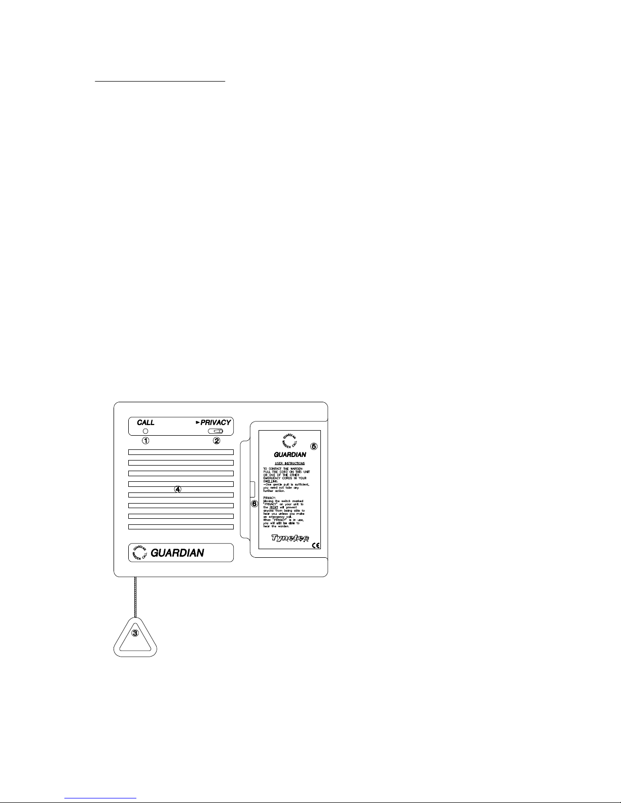
1. THE INTERCOM UNIT
Each dwelling on your scheme will be fitted with an Intercom Unit, there may also be others in
communal areas, corridors, toilets, etc.
Any Intercom Unit or associated pullcords in the bedrooms, bathrooms, etc, can be used to place an
emergency alarm call on the system.
Basic operating instructions are printed on each Intercom Unit.
The standard Intercom Unit has only two external controls, one is a front panel switch and the other an
orange alarm pullcord.
The front panel switch controls a PRIVACY facility in the Intercom Unit. Switching the privacy function
ON disables the microphone function of the Intercom, thereby preventing eavesdropping.
Operation of the alarm pullcord places an emergency call on the system which is then reported to the
Portable Master Unit or Central Control.
Operation of the alarm pullcord or any associated pullcords in the dwelling automatically overrides the
privacy facility for approx 15 minutes.
The red call LED indicator on the Intercom Unit will illuminate when an alarm call is initiated.
The LED will remain illuminated until the alarm call is answered in the onsite mode of operation. If the
system is operating in the offsite mode the LED will illuminate momentarily then a reassurance tone is
sounded from the Intercom Unit until the call is answered by Central Control.
1. CALL LED INDICATOR
2. PRIVACY ON/OFF SWITCH
3. ALARM PULLCORD
4. LOUDSPEAKER
5. OPERATING INSTRUCTIONS
6. CONNECTOR FOR PLUG-IN
PORTABLE MASTER UNIT
(c) Tynetec Limited 2001 FM0313e.PDF issue A Page 2
Page 3
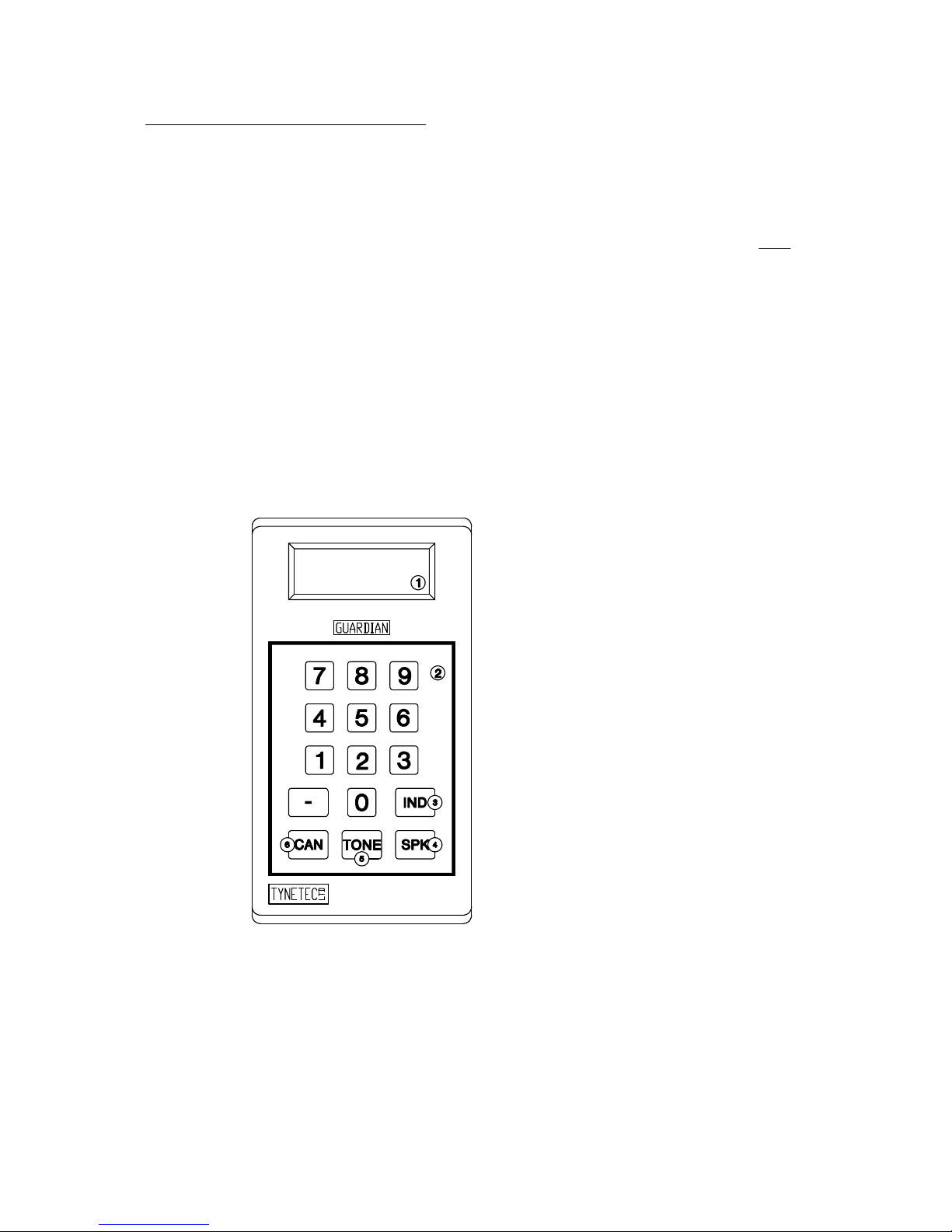
2. THE PORTABLE MASTER UNIT
The Portable Master Unit should be plugged into an Intercom Unit on the system at all times.
The Portable Master Unit will automatically alert you of any alarm calls and will also allow you full
control of the system in onsite mode.
If you have been supplied with two or more Portable Master Units it is important that only ONE is
plugged into the system at any one time.
When the Portable Master Unit is first plugged into an Intercom Unit the following will be displayed :
GUARDIAN 2/3
SYSTEM READY
Always press the 'CAN' key once, either of the following will be displayed :
SYSTEM READY SYSTEM READY
NO CALLS - - - - or FAULTS EXIST
Both displays are normal and will be explained later.
1. LCD DISPLAY
2. MEMBRANE KEYPAD
3. INDEX KEY
4. SPEAK KEY
5. TONE KEY
6. CANCEL KEY
(c) Tynetec Limited 2001 FM0313e.PDF issue A Page 3
Page 4

3. TO ANSWER AN ALARM CALL
Provided the system is operating in the ONSITE mode, all alarm calls will be signalled to the Portable
Master Unit.
AN ALARM WILL BE SIGNALLED :
1. An AUDIBLE alarm tone will sound.
2. The DISPLAY will show the alarm identity and type.
TO ANSWER ANY ALARM CALL :
1. Press the SPK key to answer an alarm call.
2. Press and HOLD the SPK key to speak to the resident.
3. RELEASE the SPK key to listen to the resident.
4. Press the CAN key once to cancel the call.
Two basic types of alarm calls can be detected by the system, those initiated by a resident and those
triggered automatically.
ALARM CALL FROM A RESIDENT :
An alarm call placed on the system by a resident will normally be from the Intercom Unit or a remote
pullcord within the dwelling. Answer the call as described above. The following displays may occur :
FLAT - - 23 a call has been made from the Intercom Unit in flat 23.
INTERCOM ALARM
FLAT - - 23 a call has been made from a remote Pullcord in flat 23.
PULLCORD ALARM
FLAT - - 23 a call has been made from the Pendant of the resident of flat 23.
PENDANT ALARM
SYSTEM READY will be displayed when the call is cancelled.
NO CALLS - - - -
(c) Tynetec Limited 2001 FM0313e.PDF issue A Page 4
Page 5

ALARM CALLS DETECTED AUTOMATICALLY :
An alarm call triggered automatically may be from a smoke detector or a system fault. Answer and deal
with the call as described above. The following displays may occur :
FLAT - - 23 will be displayed if a smoke alarm has detected a fire in flat 23.
SMOKE ALARM
FLAT - - 23 will be displayed if an intruder has been detected in flat 23.
INTRUDER ALARM
FLAT - - 23 will be displayed if there is an open circuit wiring fault in flat 23.
OPEN CCT FAULT
SYSTEM FAULT will be displayed if the system mains supply has failed.
MAINS FAIL
SYSTEM FAULT will be displayed if the system battery standby is running low.
LOW BATTERY
MAINS RESTORED will be displayed when the mains supply is restored.
SYSTEM FAULT will be displayed if the system telephone line has failed.
BT LINE FAILURE
BT LINE RESTORED will be displayed when the system telephone line is restored.
SYSTEM FAULT will be displayed on a PAGING Portable Master Unit only.
12V FUSE BLOWN
SYSTEM READY will be displayed when a SYSTEM FAULT call is cancelled.
FAULTS EXIST
The system will operate as normal when FAULTS EXIST is displayed but you are reminded that a
problem requires attention.
It is possible to view the contents of the system fault memory by entering a special code via the
Portable Master Unit, see section 11 of this manual.
The power supply for all the Intercom Units on your scheme is monitored by the system. Should this
supply fuse blow, a PERMANENT alarm tone will be sounded at the Portable Master Unit. This call
cannot be cancelled - call your Service Engineer immediately.
(c) Tynetec Limited 2001 FM0313e.PDF issue A Page 5
Page 6

4. TO CALL A RESIDENT
To call a resident via their Intercom Unit simply enter their flat number using the Portable Master Unit
keyboard.
The flat number is entered one digit at a time, each time you enter a new digit a tone will be heard and
the display will show the new digit and any previously entered digits.
1. Enter the flat number of the resident you wish to contact.
2. Press the TONE key to sound a call tone or
Press and HOLD the SPK key to speak directly to the resident.
3. RELEASE the SPK key to listen to the resident.
4. Press the CAN key to cancel the call.
5. The display will return to the status prior to the call being made :
SYSTEM READY SYSTEM READY
NO CALLS - - - - or FAULTS EXIST
To call any other intercom unit on the system eg. common room, corridor, etc, use the same procedure
as above but enter the actual channel number of the intercom unit.
5. SECOND CALL WAITING
When the system is being used to speak to a resident all other Intercom Units are continuously
monitored for alarm calls.
If another alarm call is detected you will be notified by a short BLEEP every 5 seconds.
1. On hearing the intermittent bleep you should conclude your conversation as quickly as possible and
press the CAN key once.
2. The display will change to show the channel number of the second call.
3. Press the SPK key to answer the call in the normal way or
Press the CAN key a second time (in the gap between the alarm tone audible signal) this will check the
system memory to determine if more than one new alarm call exists. The display will change with each
press of the CAN key to show all alarm calls detected.
4. Stored alarm calls can be answered in any order by pressing the SPK key when the required channel
number is displayed.
5. Press the CAN key to cancel the call.
(c) Tynetec Limited 2001 FM0313e.PDF issue A Page 6
Page 7

6. SPECIAL FUNCTION KEYS (OPTIONAL)
The Guardian 3 Warden Call system may be fitted with an optional facility to allow operation of the front
door lock, electric keysafe, etc.
The output can be operated during speech to any Intercom Unit by pressing the relevant digit key on the
Portable Master Unit. See the list at the back of this manual for the digit key functions available.
1. Answer (or call) any Intercom Unit in the normal way.
2. When in the LISTEN mode, press the required digit key once.
3. The output will operate for a preset time, typically 10 seconds.
4. Press the CAN key to cancel the call in the normal way.
7. PUBLIC ADDRESS FACILITY (OPTIONAL)
The Guardian 3 Warden Call system may be fitted with an optional facility to allow general
announcements to be made to all residents.
This facility can only be used from ONE of FOUR specified Intercom Units. See the back page of this
manual for there locations.
The system may be configured so you can speak to all or one of two separate groups within the
scheme.
To use the Public Address Speech facility you must enter ONE of three special codes using the
Portable Master Unit keyboard.
1. Enter 1000 on the Portable Master Unit to call ALL Intercoms.
Enter 1001 on the Portable Master Unit to call GROUP 1 Intercoms.
Enter 1002 on the Portable Master Unit to call GROUP 2 Intercoms.
2. Press the SPK key once to sound an all call announcement tone.
3. Press and HOLD the SPK key whilst an announcement is being made.
4. Press the CAN key to return the system to normal operation.
(c) Tynetec Limited 2001 FM0313e.PDF issue A Page 7
Page 8

8. FIRE ALARM TONE FACILITY (OPTIONAL)
The Guardian 3 Warden Call system may be fitted with an optional fire alarm tone facility which is linked
to the main building fire alarm system.
If the main fire alarm system detects a fire, the alarm bells or sirens will sound and an auxiliary fire
alarm tone will also be sounded through all the Intercom Units on the system.
The fire alarm tone is an intermittent WARBLE TONE and is different to all other tones the system
normally uses.
The fire alarm tone can also be started manually by entering a special code using the Portable Master
Unit keyboard.
1. Enter 1003 using the Portable Master Unit keyboard.
2. Press the SPK key once, the fire tone is now sounded through ALL Intercoms.
3. Press the CAN key to return the system to normal operation.
9. OPERATING MODE
The Guardian 3 Warden Call system may have the facility for connection to a remote Central Control
answering station to ensure 24 hour alarm coverage.
The system can be switched to Central Control operation (offsite mode) via the keyswitch or the
Portable Master Unit keyboard. The keyswitch module indicates onsite mode with a green LED and
offsite mode with a red LED.
If the system is operating in the ONSITE mode and an alarm call remains un-answered for a preset time
period (typically 6 minutes) the system will automatically select the OFFSITE mode and divert the call
to Central Control.
The system monitors the telephone line and should a fault develop this will inhibit calls from being
transferred to Central Control. A telephone line fault will be reported on the Portable Master Unit and
may also flash a BT Line Fault beacon.
1. GREEN 'ONSITE MODE' LED INDICATOR
2. RED 'OFFSITE MODE' LED INDICATOR
3. MODE SELECTION KEYSWITCH
4. YELLOW 'CALL IN PROGRESS' LED INDICATOR
5. RED 'FAULTS EXIST' LED INDICATOR
(c) Tynetec Limited 2001 FM0313e.PDF issue A Page 8
Page 9

ONSITE / OFFSITE USING THE KEYSWITCH MODULE
For long term Central Control operation ie. over-night, use the keyswitch module usually located in the
wardens office.
TO SELECT OFFSITE MODE : 1. Turn the keyswitch to the OFFSITE position.
2. Check the red LED illuminates.
3. Remove the key from the keyswitch.
4. Remove the Portable Master Unit from the Intercom Unit.
TO RETURN TO ONSITE MODE : 1. Check the Call in Progress LED is NOT illuminated.
2. Turn the keyswitch to the ONSITE position.
3. Check the green LED illuminates.
4. Remove the key from the keyswitch.
5. Replace the Portable Master Unit in an Intercom Unit.
ONSITE / OFFSITE USING THE PORTABLE MASTER UNIT
The Portable Master Unit can be used to confirm the current operating mode or change the operating
mode by entering one of three special codes :
CURRENT OPERATING MODE : 1. Enter the code 1004 via the Portable Master Unit.
2. Press the SPK key followed by the CAN key.
3. The display will show :
SYSTEM READY
NO CALLS 1005 The system is currently operating in the ONSITE mode.
SYSTEM READY
NO CALLS 1007 The system is currently operating in the OFFSITE mode.
TO SELECT ONSITE MODE : 1. Enter the code 1005 via the Portable Master Unit.
2. Press the SPK key followed by the CAN key.
3. The display will show :
SYSTEM READY
NO CALLS 1005 The system is now operating in the ONSITE mode.
TO SELECT OFFSITE MODE : 1. Enter the code 1007 via the Portable Master Unit.
2. Press the SPK key followed by the CAN key.
3. The display will show :
SYSTEM READY
NO CALLS 1007 The system is now operating in the OFFSITE mode.
SYSTEM READY
NO CALLS 1005 The system is still operating in the ONSITE mode.
Note : it is not possible to select offsite mode if a telephone line fault exists. If the system is operating
in offsite mode and a telephone line fault develops then the system will switch back onsite mode.
(c) Tynetec Limited 2001 FM0313e.PDF issue A Page 9
Page 10

10. TO PARK AN ALARM CALL
If the system is permanently re-reporting an Intercom, Pullcord, Pendant or Smoke alarm call due to a
fault condition, this call can be taken out of service or PARKED using the Portable Master Unit:
1. Press the SPK key once to answer the alarm call.
2. Press the 5 key once to PARK the Intercom Unit.
3. Press the CAN key to cancel the call.
SYSTEM READY will be displayed when the Intercom Unit is parked.
FAULTS EXIST
FLAT - - 23 will be displayed if the system fault memory is viewed
INTERCOM PARKED
If you are unable to clear any fault conditions contact your Supervisor or Service Engineer immediately.
11. TO VIEW FAULT MEMORY
The Guardian 3 warden call system can store a number of faults in memory to allow the remainder of the
system to operate as normal until the faults are cleared.
If after the CAN key is pressed the display shows :
SYSTEM READY
FAULTS EXIST
This means the system memory has stored one or more fault conditions. If a Guardian 3 Status Module
is fitted the red fault LED will also be illuminated.
It is possible that you may forget the identity and type of faults which are stored in the system memory,
see below.
TO VIEW THE FAULT MEMORY :
To inspect the system fault memory a special code is entered using the Portable Master Unit keyboard
1. Enter the code 1008 via the Portable Master Unit.
2. Press the SPK key followed by the CAN key.
3. The display will automatically sequence through all the faults stored in the system memory.
4. After the last fault has been presented FAULTS EXIST will be displayed again.
(c) Tynetec Limited 2001 FM0313e.PDF issue A Page 10
Page 11

TO REMOVE FAULTS FROM MEMORY :
To clear a fault from the system memory the problem causing the fault must be rectified, then the
associated Intercom Unit must be called back.
Any SYSTEM FAULTS stored in memory ie. MAINS FAIL, BT LINE FAULT, etc, will automatically be
removed when the fault is rectified.
Follow the procedure described above and make a note of all the channel numbers with fault conditions.
1. Enter the faulty channel number using the Portable Master Unit keyboard.
2. Press the SPK key once.
3. Press the CAN key to cancel the call.
4. If the fault has been rectified it will be cleared from the memory, if it still exists it will be re-reported to
the Portable Master Unit.
5. If the fault re-reports, press the SPK key followed by the 5 key and the fault will be PARKED in the
system memory again.
6. Repeat for all faulty channel numbers stored in the memory.
12. INDEX FACILITY
Daily calls to all residents can be greatly simplified by using the INDEX facility. You can start sequential
calls at any flat number.
1. Call the first resident in the normal way.
2. When you wish to call the next resident, rather than pressing the CAN key to end the call, press the
IND key once. The current call will be cancelled and the display will change to show the next channel
number.
3. Press the SPK key and you will engage the channel displayed.
4. If you wish to skip a resident, press the IND key again and the display will change to the next
channel number. This procedure can be repeated at will.
5. Press the CAN key to terminate sequential calls.
(c) Tynetec Limited 2001 FM0313e.PDF issue A Page 11
Page 12

13. CLOCK FACILITY
The Guardian 3 Warden Call System has a real time clock and calendar which is used to record all
system activity with the time and date of each event if a printer is connected.
TO CHECK THE SYSTEM TIME : 1. Enter the code 2000 via the Portable Master Unit.
2. Press the SPK key followed by the CAN key.
3. The display will show :
SYSTEM READY
NO CALLS 1630 The time is 16:30 (24 hour format)
To correct the time enter the new time via the Portable Master Unit keypad and press the SPK key
followed by the CAN key.
TO CHECK THE SYSTEM DATE : 1. Enter the code 2001 via the Portable Master Unit.
2. Press the SPK key followed by the CAN key.
3. The display will show :
SYSTEM READY
NO CALLS 0411 The date is the 04 of November (Date / Month)
To correct the date enter the new date via the Portable Master Unit keypad and press the SPK key
followed by the CAN key.
(c) Tynetec Limited 2001 FM0313e.PDF issue A Page 12
Page 13

14. SPECIAL CODES AND INFORMATION
Notes Function Key
SPECIAL FUNCTION KEYS :
Notes Location Chan
PUBLIC ADDRESS INTERCOM LOCATIONS :
System Reset 4000
Activity Monitor Reset 3004
Set Date (DDMM) 2001
Set Time (HHMM) 24 Hr Clock 2000
Not Applicable 1009
View Fault Memory 1008
Select Offsite Operating Mode 1007
Not Applicable 1006
Select Onsite Operating Mode 1005
Operating Mode Enquire 1004
All Call Fire Alarm Tone Mode 1003
Group 2 Public Address Mode 1002
Group 1 Public Address Mode 1001
All Call Public Address Mode 1000
Notes Function Code
(c) Tynetec Limited 2001 FM0313e.PDF issue A Page 13
 Loading...