

Tymetal Corp. TYM 1000, TYM 2000 Installation Manual
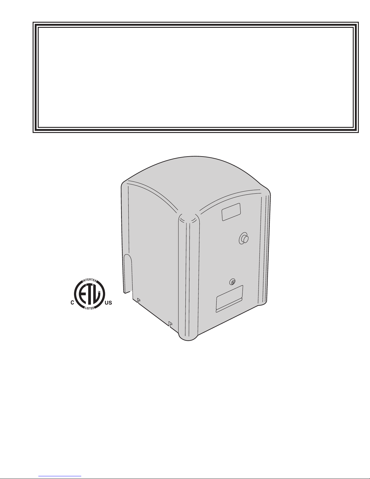
TYM 1000/2000
Slide Gate Operator
Installation Guide
Operator models contained in this manual
conform to UL325 standard for use in
Class I, II, III, and IV applications
Toll Free (800)328-GATE (4283) • Fax (518)692-9404
Tymetal Corp.
Greenwich, NY • Pearland, TX
www.tymetal.com
Rev 9 02/14
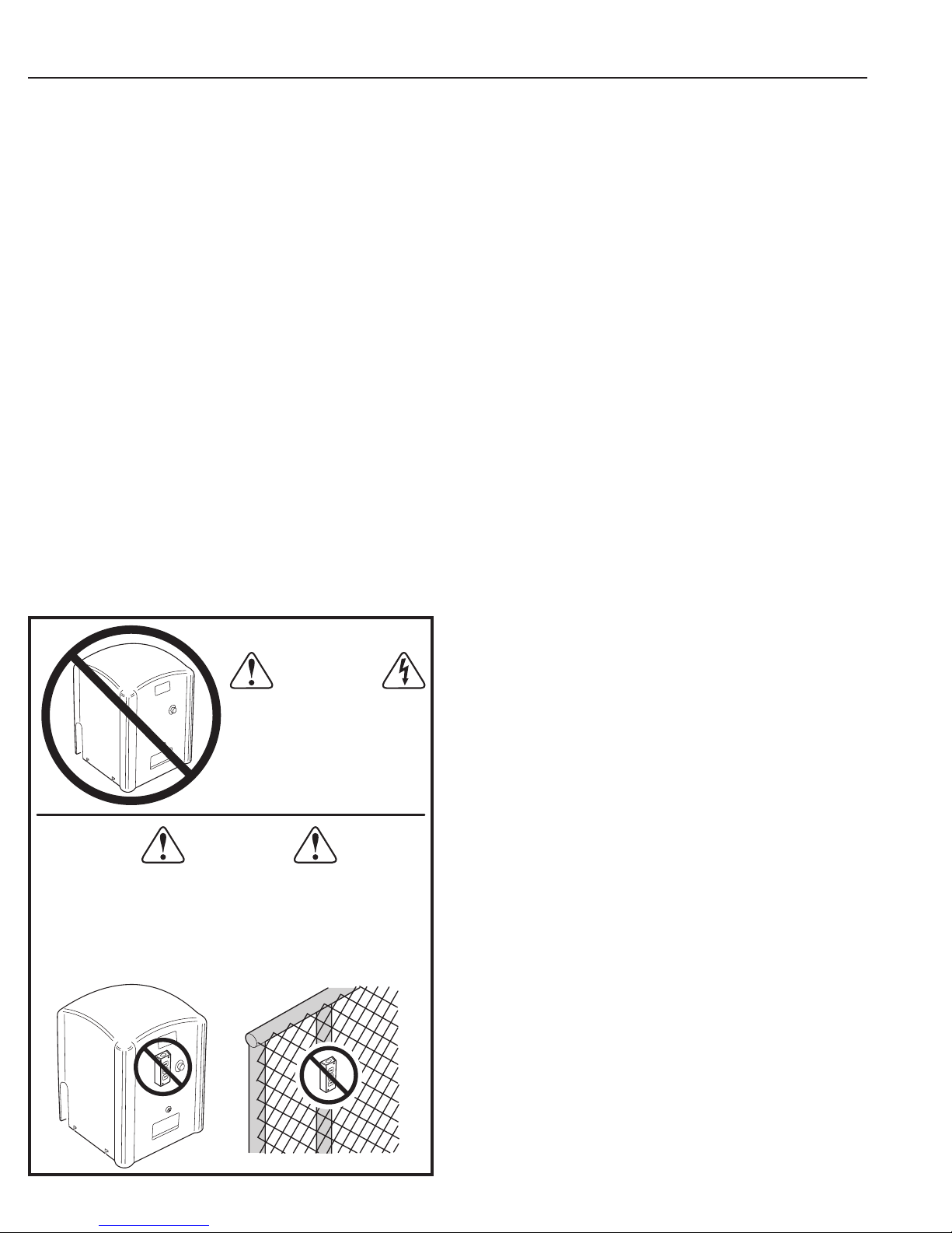
Table of Contents
Pre-installation Information ..................................1
Before You Begin... ......................................1
Always Check the Gate’s Action ............................1
Gate Operator Classications ..............................1
Approved Obstruction Detection Devices .....................1
Safety Information and Warnings .............................1
Regulatory Warnings .....................................1
Wiring Specications .......................................2
AC Power Wiring ........................................2
DC Control and Accessory Wiring ...........................2
Mounting Pad Installation ....................................3
Gate Preparation ........................................3
Gate Bracket and Chain Assembly ............................5
Operator Preparation .......................................6
Vent Plug Installation .....................................6
Operator Setup ............................................6
Controller Access .......................................6
AC Power Connection ....................................6
Earth Ground ...........................................6
Limit Nuts Rough Adjustment ..............................7
Limit Nuts Fine Adjustment ................................7
Controller Features .........................................8
Indicator Descriptions. . . . . . . . . . . . . . . . . . . . . . . . . . . . . . . . . . . . . . .9
Terminal Descriptions ......................................10
Operator Accessory Connections ............................11
Basic Controller Programming ..............................12
Programming Overview ..................................12
Entering Programming Mode .............................12
Exiting Programming Mode ...............................12
Programming Keystrokes ................................12
Left or Right Hand Operation .............................12
Dual Gate Enable ......................................12
Auto Close Timer .......................................12
Run Alarm and Pre-start Alarm ............................13
Maximum Open Direction Current Setting ....................13
Maximum Close Direction Current Setting ...................13
WARNING
ONLY QUALIFIED TECHNICIANS
SHOULD WORK ON
TYMETAL
LINEAR SLIDE GATE
OPERATORS
WARNING
CONTROLS INTENDED FOR USER ACTIVATION MUST BE
LOCATED AT LEAST SIX FEET (6') AWAY FROM ANY MOVING
PART OF THE GATE AND WHERE THE USER IS PREVENTED
FROM REACHING OVER, UNDER, AROUND OR THROUGH THE
GATE TO OPERATE THE CONTROLS. OUTDOOR OR EASILY
ACCESSIBLE CONTROLS SHALL HAVE A SECURITY FEATURE
TO PREVENT UNAUTHORIZED USE.
Advanced Controller Programming ...........................14
Entering Advanced Programming Mode .....................14
Maximum Run Time ....................................14
Single Button Input Setup ................................14
Stagger Mode (Rarely used in slide gate installations) ..........14
Stagger Delay Time (Rarely used in slide gate installations) .....15
Auxiliary Relay Mode ....................................15
Reverse Delay Time ....................................15
Reset Cycle Count .....................................16
Maintenance Alert Trigger ................................16
Mid-travel Stop Position .................................16
Motor Type Selection ....................................16
Radio Enable ..........................................17
Antenna Installation .....................................17
Radio Transmitter Learn .................................17
Radio Transmitter Delete .................................17
MGT Obstacle Transmitter Learn ..........................17
MGT Obstacle Transmitter Delete ..........................17
Reset Controller to Factory Defaults ........................17
APeX v 1.4 Quick Programming Guide ........................18
Loop Layout Illustration ....................................20
Loop Detector Operating Instructions .........................21
Using Gate Reversing Edge Transmitters ......................23
Reversing Edge Layout Illustration ...........................24
Photoeye Installation Illustration .............................25
Picket Gate Installation .....................................26
Dual Gate Installations .....................................27
Gate Operation. . . . . . . . . . . . . . . . . . . . . . . . . . . . . . . . . . . . . . . . . . . .28
Open Button ..........................................28
Close Button ..........................................28
Stop Button ...........................................28
Single Input ...........................................28
Fire Department Input ...................................28
Fire Department Access .................................28
Open Input ............................................28
Open Obstruction ......................................28
Close Obstruction ......................................28
Reverse Input .........................................28
Open Loop ............................................28
Reverse Loop .........................................28
Shadow/reset Loop .....................................28
Operation Indications ......................................29
Power-up Display ......................................29
Idle Condition .........................................29
Last Gate Position/Condition ..............................29
Pre-start Delay ........................................29
Reverse Delay .........................................29
Run Timer ............................................29
Error Indications ..........................................29
Entrapment ...........................................29
COMM LINK Connection Failure ...........................29
MGT Obstacle Transmitter Trouble .........................29
Maximum Run Time Exceeded ............................29
Troubleshooting ..........................................30
Contacting Technical Support ............................ .30
Operator fails to start ....................................30
Motor operates, but gate does not move .....................30
Motor sounds like it is working harder than normal .............30
Limit switch getting out of time ............................30
Gate stopping part way open or closed
(but no visible obstruction) ...............................30
Gate staying open with automatic system ....................30
How to Order Replacement Parts ..........................30
Safety Information .........................................31
Manual Disconnect ........................................32
Gate Obstruction Sensing Information ........................32
TYM 1000/2000 Exploded View and Parts List ..................33
Preventative Maintenance ..................................35
General ..............................................35
Lubrication ............................................35
6-Month Preventative Maintenance .........................35
FCC Notice ...............................................35
Gate Operator Installation Checklist ..........................36

Pre-installation Information
Before You Begin...
Before unpacking, inspect the carton for exterior damage. If you nd
damage, advise the delivery carrier of a potential claim. Inspect your
package carefully. You can check your accessory box parts with the
enclosed packing slip for your convenience. Claims for shortages will be
honored for only 30 days from the date of shipment.
Before installing the operator, read this manual completely to ensure all
requirements for proper installation are present. Verify that the voltage to be
used matches the voltage of the operator.
If you have any questions about the requirements for proper installation
of this gate operator contact technical support at 800-328-4283
Safety Information and Warnings
THE FOLLOWING FORMATS ARE USED FOR SAFETY NOTES
IN THESE INSTRUCTIONS.
CAUTION
This type of warning note is used to
indicate the possibility of damage to the
gate or gate operator.
WARNING
This type of warning note is used to
indicate possible mechanical hazards
that may cause serious injuries or death.
Always Check the Gate’s Action
It’s very important before installing the gate operator to
make sure the gate’s slides free and level throughout
the entire opening distance. If the gate does not
seem to operate properly, it may affect the operator
performance or greatly shorten the life of the unit. The
gate should also be designed so that airow is ample to
prevent wind resistance and drag.
Gate Operator Classications
All gate operators can be divided into one of four different classications,
depending on their design and usage. Install this gate operator only
when the operator is appropriate for the construction and usage class
as dened below:
• Class I Residential Vehicular Gate Operator
A vehicular gate operator intended for use in a home or for one to
four single family dwellings with a common garage or parking area
associated with these dwellings.
• Class II Commercial / General Access Vehicular Gate
Operator
A vehicular gate operator intended for use in a commercial location or
building such as a multi-family housing unit of ve or more single family
units, hotel, retail store or other building servicing the general public.
• Class III Industrial / Limited Access Vehicular Gate
Operator
A vehicular gate operator intended for use in an industrial location or
building such as a factory or loading dock area or other location not
intended to service the general public.
• Class IV Restricted Access Vehicular Gate Operator
A vehicular gate operator intended for use in a guarded industrial
location or building such as an airport security area or other restricted
access locations not servicing the general public, in which unauthorized
access is prevented via supervision by security personnel.
Regulatory Warnings
Read the following before beginning to install this slide gate
operator:
IMPORTANT INSTALLATION
REVIEW THESE INSTALLATION SAFETY
1. READ AND FOLLOW ALL INSTALLATION INSTRUCTIONS.
2. Read the yellow “Safety Instructions” brochure enclosed with the packet
3. ALL ELECTRICAL CONNECTIONS TO THE POWER SUPPLY MUST
4. A separate power-disconnect switch should be located near the operator
5. Install the enclosed warning signs on both sides of the gate. A minimum
6. Never reach between, through or around the fence to operate the gate.
7. Never connect a button station within reach of the gate or on the side of
8. Do not adjust the operator controller’s current sensing feature too high. It
Approved Obstruction Detection Devices
The following contact or non-contact obstruction detection
devices have been approved for use with this slide gate
operator as part of a UL325 compliant installation:
• Contact Edges
Miller Edge Models MGO20, MGR20, MGS20, ME120
• Photoeyes
MMTC Model IR-55 (165’ range)
MMTC Model E3K (28’ range)
TYM 1000/2000 Slide Gate Operator Installation Guide - 1 - Rev 9 02/14
9. You must install all required safety equipment.
10. UL325 Compliance requires the use of contact edges or photoelectric
11. The operator is intended for installation only on gates used for vehicles.
This type of warning note is used to
indicate possible electrical shock hazards
that may cause serious injuries or death.
SAFETY INSTRUCTIONS
TO REDUCE THE RISK OF SEVERE
INJURY OR DEATH TO PERSONS,
STEPS BEFORE PROCEEDING
of information. If any pages are missing or are unreadable, or you do not
have the safety instructions, please call Tymetal Corp. at 1-800-328-4283
to request additional copies.
BE MADE BY A LICENSED ELECTRICIAN AND MUST OBSERVE ALL
NATIONAL AND LOCAL ELECTRICAL CODES.
so that primary power can be turned off when necessary.
of two (2) WARNING SIGNS shall be installed, one on each side of the
gate where easily visible.
the gate operator.
should be adjusted high enough to keep the gate from falsely triggering
the sensing, but no higher than necessary for the gate to operate. DO
NOT DEFEAT THE PURPOSE OF THIS FUNCTION!
controls on all automatic or remotely-controlled gate operators.
Pedestrians must be supplied with a separate access opening. The
pedestrian access opening shall be designed to promote pedestrian
usage. Locate the gate such that persons will not come into contact with
the vehicular gate during the entire path of travel of the vehicular gate.
WARNING
WARNING

Wiring Specications
Refer to the following steps for details on power and
accessory wiring for the operator.
WARNING
ALL AC ELECTRICAL CONNECTIONS TO THE POWER
SOURCE AND THE OPERATOR MUST BE MADE BY A
LICENSED ELECTRICIAN AND MUST OBSERVE ALL
NATIONAL AND LOCAL ELECTRICAL CODES.
USE COPPER WIRE ONLY!
AC Power Wiring
1. Find the listing on this page corresponding to the model,
voltage and horsepower rating of your operator.
2. The distance shown in the table is measured in feet from
the operator to the power source. DO NOT EXCEED
THE MAXIMUM DISTANCE. These calculations have
been based on standard 115 V and 230 V supplies
with a 10% drop allowable. If your supply is under the
standard rating, the runs listed may be longer than what
your application will handle, and you should not run wire
too near the maximum distance for the gauge of wire
you are using.
3. When large-gauge wire is used, a separate junction box
(not supplied) may be needed for the operator power
connection.
4. Wire length calculations are based on the National
Electrical Code, Article 430 and have been carefully
determined based on motor inrush, brake solenoids, and
operator requirements.
5. Connect power in accordance with local codes. The
green ground wire must be properly connected.
6. Wire insulation must be suitable to the application.
7. TYM 1000 Only: Electrical outlets are supplied in all
115VAC models for convenience with occasional use
or low power consumption devices only. If you choose
to run dedicated equipment from these devices, it will
decrease the distance for maximum length and the
charts will no longer be accurate.
8. TYM 1000 is 115v 1ph 6.0 amp draw. TYM 2000 is
208/230v 1ph 4.7amp draw.
9. TYM 2000 operator is dual (208/230) voltage single
phase. No transformer tap change or motor rewiring is
required for either voltage.
10. EARTH GROUND REQUIRED see pg. 6
DC Control and Accessory Wiring
1. Open, Close, Stop control functions are 5 VDC. Use
20 ga stranded up to 2000’. Use 18 ga stranded from
2000’ to 5000’.
2. Control wiring must be run in a separate conduit from
power wiring and conduits must be separated my
minimum 12”. Running them together may cause
interference and faulty signals in some accessories.
3. A three-wire shielded conductor cable is required to
connect two operators together for dual operation. You
must use Belden 8760 Twisted Pair Shielded Cable (or
equivalent) only – P/N 2500-1982, per foot). See Page
25 for details of this connection. Note: The shield wire
should be connected in both the operators.
MODEL TYM 1000/2000 POWER WIRING
VOLTS & HP
115 VOLTS
1/2-HP
208 VOLTS
1-HP
230 VOLTS
1-HP
MAXIMUM DISTANCE (FEET)
SINGLE DUAL
222 111 12
354 177 10
566 283 8
900 450 6
1430 715 4
544 272 12
864 432 10
1374 686 8
2184 1092 6
3476 1738 4
640 320 12
1016 508 10
1616 808 8
2570 1285 6
4090 2045 4
WIRE GAUGE
TYM 1000/2000 Slide Gate Operator Installation Guide - 2 - Rev 9 02/14
Mounting Pad Installation
The gate operator mounts bolted to a custom poured
concrete mounting pad. The pad supports the operator and
prevents it from moving during operation.
An optional post mount kit is also available (P/N 2120-483)
which allows installation without a concrete mounting pad.
Gate Preparation
Before installing the pad, make sure the gate rolls or slides
freely, and that all exposed rollers are properly covered. The
gate must be covered with fabric with openings no larger
than 2-1/4” in size, to a minimum height of 72” above ground
level. On picket-style gates, if pickets are spaced less than
2-1/4” apart, mesh is optional.
Mounting Pad Specications
Recommended pad size is 21” x 21” minimum. Pad depth
should be set according to local codes and at least as deep
as frost line. 5/8” J-bolts may be set into the concrete before
it sets following the dimensions shown, or drilled after the
concrete sets.
WARNING
The operator is intended for installation only on gates used
for vehicles. Pedestrians must be supplied with a separate
access opening. The pedestrian access opening shall be
designed to promote pedestrian usage. Locate the gate such
that persons will not come into contact with the vehicular
gate during the entire path of travel of the vehicular gate.
WARNING
The gate must be installed in a location so that enough
clearance is supplied between the gate and adjacent
structures when opening and closing to reduce the risk of
entrapment. Swing gates shall not open into public areas.
TYM 1000/2000 Slide Gate Operator Installation Guide - 3 - Rev 9 02/14
Figure 1. Mounting Pad Specications
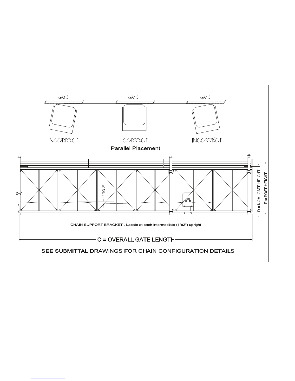
Figure 2: Operator Positioning - Parallel Placement
TYM 1000/2000 Slide Gate Operator Installation Guide - 4 - Rev 9 02/14
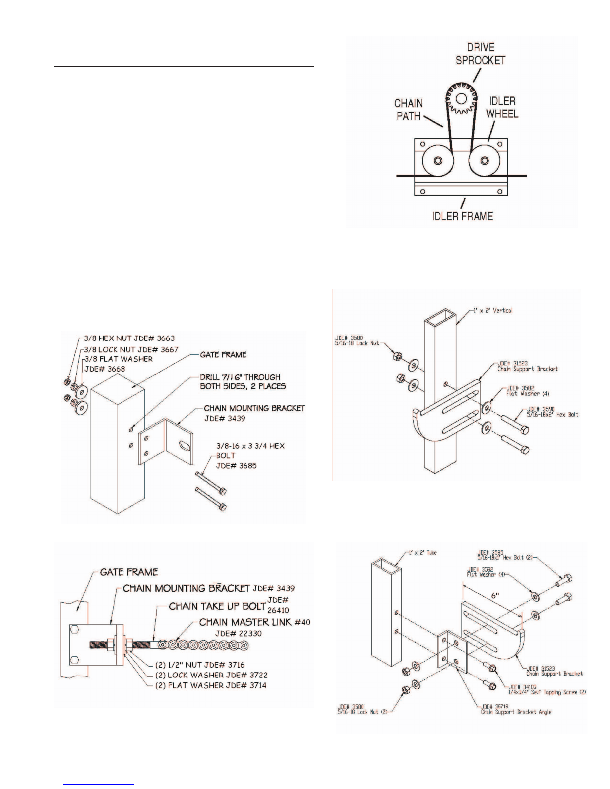
Gate Mounting Bracket and Chain
Assembly
Your gate should be hung level and move freely by hand in
both directions before attaching the operator drive chain.
Slide the gate to the fully open position. Line up the slot
in the chain mounting bracket with the bottom of the idler
wheel on the operator. Mark the leading edge of the gate
frame using the chain mounting bracket as a template. Drill
and mount the chain mounting bracket as shown in Figure
3.
Slide the gate to the folly closed position and mount the
other chain mounting bracket to the rear edge of the gate
frame the same way.
Attach the chain to both chain mounting brackets as shown
in Figure 4, route the chain through the operator as shown
in Figure 5.
Install chain support brackets as shown in Figure 6A or 6B
as applicable to gate style. Brackets should support the
chain but must not hit the operator. See Figure 1.
Adjust the chain to have 1-2” of sag between the chain
supports as shown in Figure 2.
Figure 5: Chain Path
Figure 6A: Standard
Figure 3: Mounting Gate Bracket to Gate
Figure 4: Chain to Bracket Assembly
TYM 1000/2000 Slide Gate Operator Installation Guide - 5 - Rev 9 02/14
Figure 6B: Ornamental
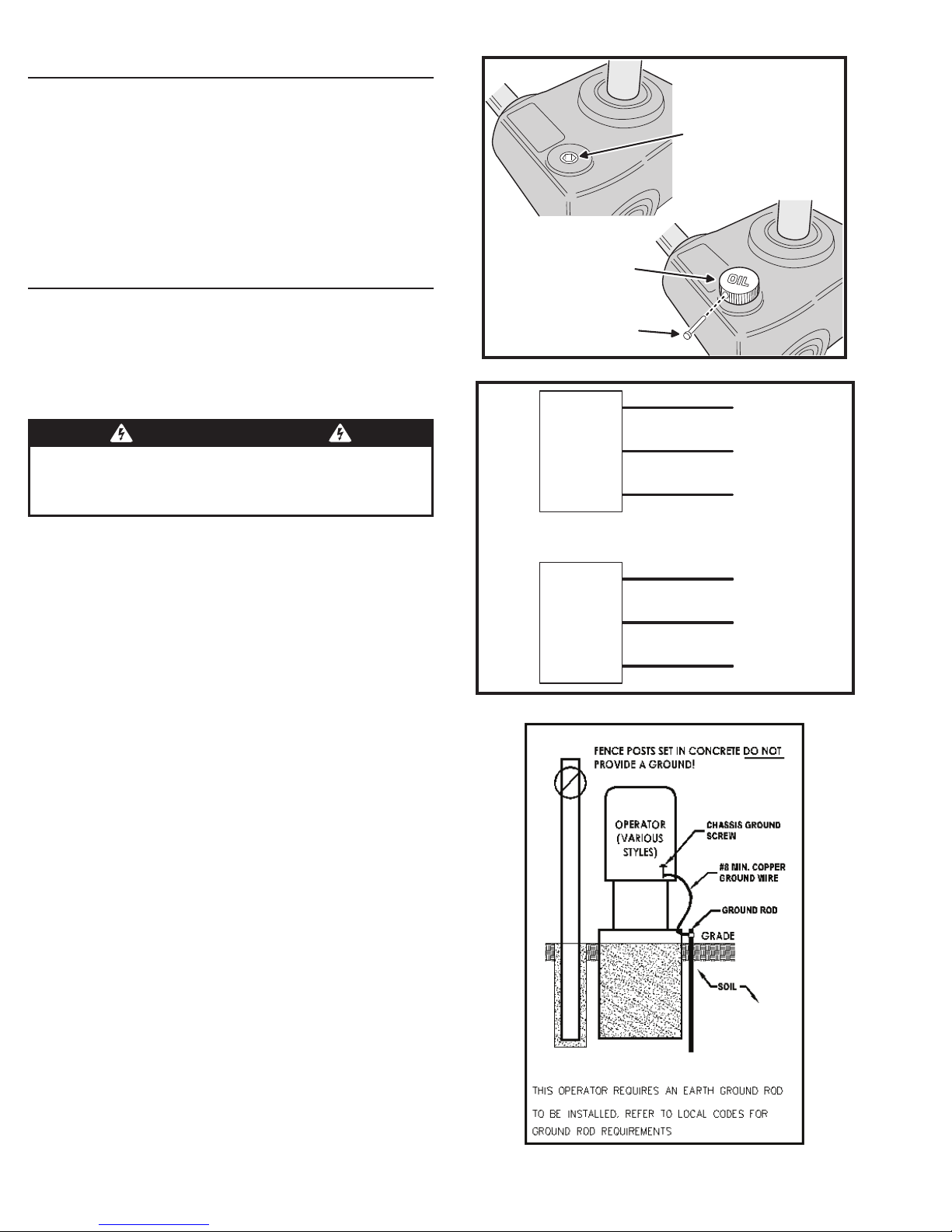
Operator Preparation
Vent Plug Installation
In order to keep gear oil from spilling out during shipping,
gear reducers used in this gate operator have either a solid
plug, or a sealed vent plug, installed at the factory.
For operators with a solid plug, replace the solid plug with
the vent plug provided (see Figure 7).
With the vent plug installed, remove the vent plug’s breather
pin to allow the gear box to vent (see Figure 7).
Operator Setup
GEAR
REDUCER
REMOVE THE
SOLID PLUG
WITH AN ALLEN
WRENCH
INSTALL THE VENT PLUG
(IF NOT ALREADY INSTALLED)
Controller Access
The Controller is protected by a plastic dust cover. To
remove the dust cover, loosen the cover’s wing-screw and
lift the cover off.
AC Power Connection
WARNING
ALL AC ELECTRICAL CONNECTIONS TO THE POWER
SOURCE AND THE OPERATOR MUST BE MADE BY A
LICENSED ELECTRICIAN AND MUST OBSERVE ALL
NATIONAL AND LOCAL ELECTRICAL CODES
All Tymetal Corp. gate operators are supplied with a power
disconnect switch to turn on and off the power available to
the operator (see Figure 8). Following wiring specications
on Page 2, incoming power should be brought into the
operator and connected to the labeled pigtails from the
disconnect box. A wiring connections print can also be
found on the label inside the cover of the operator.
Proper thermal protection is supplied with the operator. The
motor contains a thermal overload protector to guard from
overheating the motor due to overload or high-frequency
operation. This overload protector will reset automatically
after the motor cools down.
REMOVE THE
BREATHER PIN
Figure 7. Vent Plug Installation
110 VOLT
OPERATOR
POWER
DISCONNECT
BOX
220 VOLT
OPERATOR
POWER
DISCONNECT
BOX
BLACK
WHITE
GREEN
BLACK
BLACK
GREEN
HOT
NEUTRAL
GROUND
LINE 1
LINE 2
GROUND
Figure 8. Power Disconnect Box Wiring
Earth Ground
Install a ground rod and connect it to the operator’s frame
in every gate operator installation. A good earth ground
is necessary to allow the Controller’s built-in surge and
lightning protection circuitry to work effectively. The physical
bolting of the operator to the mounting pad is not sufcient
for a good earth ground.
3 NOTE: Do not splice the ground wire. Use a single piece
of solid copper 12 AWG wire between the ground rod
and the operator.
1. Install an 8-foot long copper ground rod next to the
operator mounting pad within three feet of the operator.
2. Use a clamp to connect a solid copper 12 AWG ground
wire to the ground rod.
3. Route the ground wire to the operator.
4. Connect the ground wire to the operator’s frame.
Figure 9. Earth Ground
TYM 1000/2000 Slide Gate Operator Installation Guide - 6 - Rev 9 02/14

Operator Setup (Continued)
Limit Nuts Rough Adjustment
The limit nuts are not preset at the factory and must be
adjusted for the length of the gate in each installation. The
limit switches are activated by two threaded nylon rotary
limit nuts which are attached to a threaded limit shaft
driven by a chain and sprockets from the main drive shaft
(see Figure 10). REMOVE THE CARDBOARD FILLER
BEFORE ADJUSTING THE LIMIT NUTS.
The Controller is factory set for right hand installations. The
left limit nut is for OPEN and the right limit nut is for CLOSE.
The limit nuts ip their denition in left hand installations.
(see left-right hand programming on Page 12).
1. With the gate connected to the gate operator in a midtravel position, the power disconnect switch turned OFF,
disconnect the operator by using the manual disconnect
lever. Once the operator has been disconnected,
manually move the gate by hand to within a foot of its
fully open position (the foot of distance is necessary to
allow for coasting of the operator after the limit switch is
tripped).
2. Once the gate is in this position, adjust the OPEN limit
nut until it activates the limit switch for open. Press down
the detent plate and rotate the nut along the threaded
shaft (see Figure 10).
3. After setting the open limit, move the gate to one foot
from fully closed and repeat the process for the CLOSE
limit nut (see Figure 10).
Left-Hand To Open Right-Hand To Open
CLOSE LIMIT OPEN LIMIT OPEN LIMIT CLOSE LIMIT
Limit Shaft
Limit Nuts
Auxiliary Limit Switches
Figure 10. Limit Box Assembly
NOTE: Auxiliary limit switches are located below limit shaft
and can be used for gate status.
PRESS DETENT
PLATE DOWN
CAUTION
If the operator is installed in a left-hand installation. Set
the Controller to left-hand operation BEFORE running the
operator for the ne setting of the limit nuts. Failure to do so
will result in over-shooting the limit switches, and can cause
damage to the operator and/or gate. Refer to programming
on Page 12.
Limit Nuts Fine Adjustment
After nishing the rough limit nut adjustments, reposition the
gate to approximately the center of travel.
1. Re-engage the operator using the disconnect handle.
2. Turn the power disconnect switch ON.
3. Stand clear of any moving parts and press the OPEN
button.
4. After the gate opens, press the CLOSE button.
5. Observe the gate in both directions as it runs through
each complete cycle. Adjust the open or close limit
nuts again if necessary. Fine levels of adjustment can
be made by adjusting a few teeth on the nut at a time.
If the gate stops during travel, you may need to adjust
the Open or Close Current Setting or the Maximum Run
Timer (see Pages 13-14).
ROTATE
LIMIT NUT
Figure 11. Setting the Limits
TYM 1000/2000 Slide Gate Operator Installation Guide - 7 - Rev 9 02/14
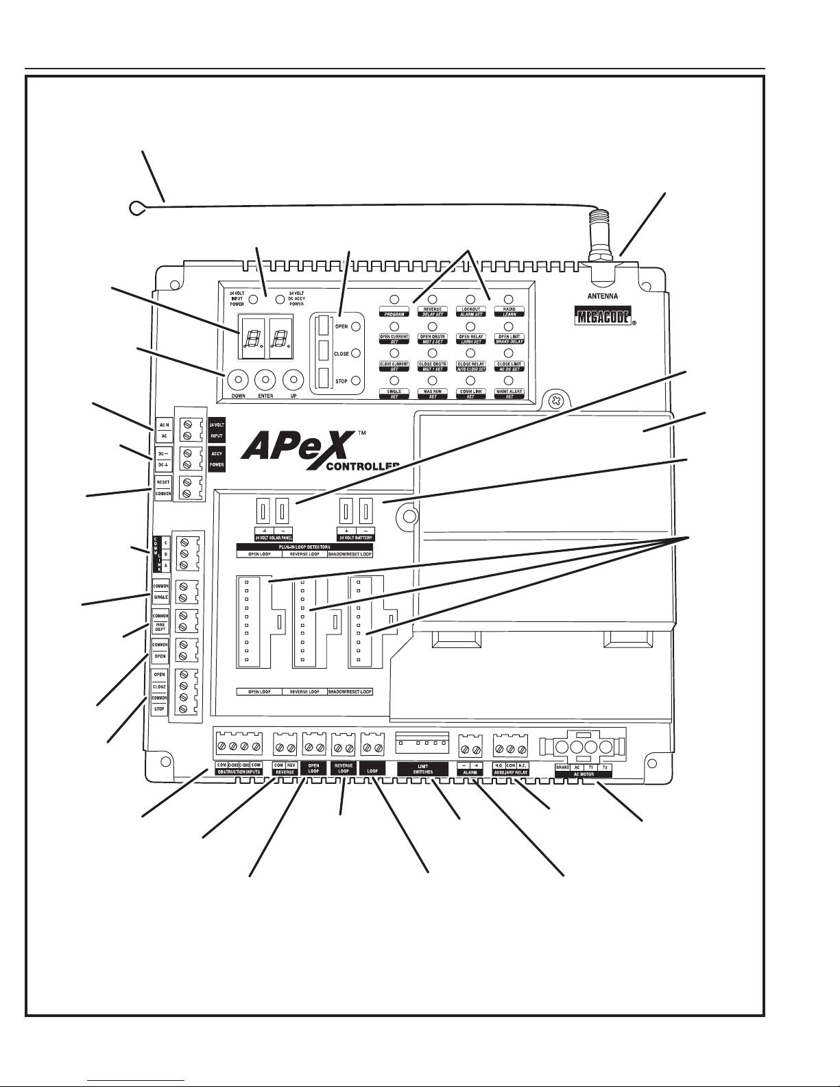
Controller Features
WHIP
ANTENNA
ANTENNA
CONNECTOR
DISPLAY
PROGRAMMING
INPUT
POWER
TERMINALS
ACCESSORY
TERMINALS
RESET
BUTTON
TERMINALS
PRIMARY/
SECONDARY
COMM LINK
TERMINALS
SINGLE
INPUT
TERMINALS
BUTTONS
POWER
POWER
INDICATORS
OPERATION
BUTTONS
OPERATION AND
PROGRAMMING
INDICATORS
SOLAR
PANEL
TERMINALS
MOTOR
BOARD
COVER
BATTERY
TERMINALS
PLUG-IN
LOOP
DETECTOR
CONNECTORS
FIRE DEPT
INPUT
TERMINALS
OPEN INPUT
TERMINALS
3-BUTTON
STATION
SHADOW/RESET
TERMINALS
OPEN AND CLOSE
OBSTRUCTION
INPUT TERMINALS
REVERSE
INPUT
REVERSE LOOP
INPUT TERMINALS
LIMIT SWITCH
INPUT TERMINALS
AUXILIARY
RELAY
TERMINALS
AC MOTOR
OUTPUT
TERMINALS
TERMINALS
OPEN LOOP
INPUT TERMINALS
SHADOW/RESET LOOP
INPUT TERMINALS
ALARM
OUTPUT
TERMINALS
Figure 12. Controller Features
TYM 1000/2000 Slide Gate Operator Installation Guide - 8 - Rev 9 02/14

Indicator Descriptions
INDICATOR DEFINITION
OPERATION PROGRAMMING
24 VOLT INPUT
POWER
24 VOLT DC
ACCY POWER
LOW VOLTAGE AC POWER IS PRESENT
LOW VOLTAGE DC POWER IS PRESENT
INDICATION WHEN LIT
DURING NORMAL OPERATION
INDICATION WHEN LIT
DURING PROGRAMMING
OPEN SIGNAL PRESENT FROM THE INTERNAL
OPEN
RECEIVER OR AN EXTERNAL DEVICE
CONNECTED TO THE OPEN INPUT TERMINAL
CLOSE
STOP
CLOSE SIGNAL IS PRESENT FROM A DEVICE
CONNECTED TO THE CLOSE INPUT TERMINAL
STOP INPUT TERMINAL IS OPEN AND
NOT CONNECTED TO COMMON
PROGRAM CONTROLLER IS IN PROGRAMMING MODE
REVERSE DELAY SET SIGNAL FROM REVERSING DEVICE IS PRESENT SET REVERSE DELAY TIME
LOCKOUT ALARM SET
RADIO LEARN
OPEN CURRENT SET
CONTROLS AND OPERATOR ARE LOCKED OUT
BECAUSE OF EXISTING TROUBLE CONDITION
BUILT-IN RECEIVER IS DETECTING A RADIO
SIGNAL FROM A REMOTE CONTROL
MOTOR CURRENT HAS EXCEEDED THE
OPEN CURRENT SETTING WHILE OPENING
SET RUN ALARM AND PRE-START ALARM
TRANSMITTERS CAN BE ENTERED INTO
MEMORY (UP TO 40 TRANSMITTERS)
SET MAXIMUM OPEN CURRENT
OPEN OBSTRUCTION TERMINAL
OPEN OBSTR MGT 2 SET
CONNECTED TO COMMON BY BEAM OR
REVERSING EDGE, OR SIGNAL FROM
SET MGT #2 FUNCTION
MGT OBSTACLE TRANSMITTER
OPEN RELAY LH/RH SET OPEN RELAY IS ACTIVATED SET LEFT-HAND RIGHT-HAND OPERATION
OPEN LIMIT BRAKE DELAY OPEN LIMIT SWITCH IS ACTIVATED
CLOSE CURRENT SET
MOTOR CURRENT HAS EXCEEDED THE
CLOSE CURRENT SETTING WHILE CLOSING
SET MAXIMUM CLOSE CURRENT
CLOSE OBSTRUCTION TERMINAL
CLOSE OBSTR MGT 1 SET
CONNECTED TO COMMON BY BEAM OR
REVERSING EDGE, OR SIGNAL FROM
SET MGT #1 FUNCTION
MGT OBSTACLE TRANSMITTER
CLOSE RELAY AUTO CLOSE SET CLOSE RELAY IS ACTIVATED SET AUTO-CLOSE TIME
CLOSE LIMIT AC DC SET CLOSE LIMIT SWITCH IS ACTIVATED SET MOTOR TYPE
SINGLE SET
SINGLE TERMINAL CONNECTED TO COMMON
BY AN EXTERNAL PUSH BUTTON OR RADIO
SET SINGLE BUTTON INPUT FUNCTION
MAX RUN SET MAXIMUM RUN TIMER HAS BEEN EXCEEDED SET MAXIMUM RUN TIME
COMM LINK SET
DUAL OPERATOR CONNECTION DETECTED,
BLINKS IF CONNECTION HAS FAILED
MAINT ALERT SET MAINTENANCE IS REQUIRED ON OPERATOR SET MAINTENANCE ALERT CYCLE COUNT
LEFT OR RIGHT
"RL"
HAND OPERATION
SINGLE OR
"PM"
DUAL GATE
AUTO CLOSE
"AC"
TIMER
RUN ALARM
"RP"
PRE-START ALARM
MAXIMUM OPEN
"OC"
CURRENT
MAXIMUM CLOSE
"CC"
CURRENT
ADVANCED
"AD"
PROGRAMMING
MAXIMUM
"RT"
RUN TIMER
TYM 1000/2000 Slide Gate Operator Installation Guide - 9 - Rev 9 02/14
APEX FUNCTION DISPLAY INDICATIONS
"SB"
"SM"
"ST"
"AR"
"RD"
"CP"
"SP"
SINGLE BUTTON
INPUT SETUP
STAGGER
MODE
STAGGER
TIME
AUXILIARY
RELAY MODE
REVERSE
DELAY TIME
CONSTANT
PRESSURE MODE
SHADOW LOOP
OPEN INHIBIT
LOW POWER
"LP"
MODE
POWER
"FS"
FAILURE MODE
SOFT START/STOP
"SS"
DURATION
RESET CYCLE
"CT"
COUNT
MAINTENANCE ALERT
"MA"
TRIGGER
MID-TRAVEL
"MT"
STOP POSITION
ANTI-TAILGATE
"AT"
ENABLE
"MO"
"RA"
"TL"
"TD"
"ML"
"MD"
"CL"
MOTOR TYPE
SELECTION
RADIO
ENABLE
LEARN
TRANSMITTERS
DELETE
TRANSMITTERS
LEARN MGT
TRANSMITTERS
ERASE MGT
TRANSMITTERS
RESET TO
FACTORY DEFAULTS

Terminal Descriptions
TERMINAL GROUP FUNCTION
AC N
AC
DC DC +
RESET
COMMON
C
A
COMMON
SINGLE
COMMON
FIRE DEPT
COMMON
OPEN
OPEN
CLOSE
COMMON
STOP
COM
O-OBS
24 VOLT INPUT
ACCESSORY POWER PROVIDES 24 VOLT DC POWER FOR ACCESSORIES. (.5A MAX)
RESET BUTTON FACTORY CONNECTED TO THE CONTROLLER’S RESET BUTTON.
COMM LINK FOR 3-WIRE NETWORK CONNECTION TO SECOND OPERATOR IN DUAL GATE INSTALLATIONS.B
SINGLE BUTTON INPUT
FIRE BOX INPUT CONNECT TO NORMALLY CLOSED SWITCH IN FIRE BOX FOR FIRE DEPARTMENT ACCESS.
OPEN INPUT
3-BUTTON
STATION INPUT
OPEN
OBSTRUCTION
INPUT
FACTORY CONNECTED TO 24 VAC FROM TRANSFORMER OR
24 VDC FROM CONTINUOUS DUTY DC SUPPLY.
CONNECT TO NORMALLY OPEN SWITCH FOR SINGLE BUTTON OPERATION. ALTERNATES
BETWEEN OPEN-CLOSE OR OPEN-STOP-CLOSE DEPENDING ON PROGRAMMING.
CONNECT TO NORMALLY OPEN DEVICES (KEYPAD, CARD READER, KEY SWITCH,
TELEPHONE ENTRY SYSTEM) TO OPEN THE GATE. A CONSTANT OPEN INPUT WILL
OVERRIDE THE MID-TRAVEL STOP AND HALT THE AUTO CLOSE TIMER UNTIL RELEASED.
CONNECT TO 3-BUTTON STATION FOR OPEN-CLOSE-STOP CONTROL. A CONSTANT OPEN INPUT
WILL OVERRIDE THE MID-TRAVEL STOP AND HALT THE AUTO CLOSE TIMER UNTIL RELEASED.
CONNECT TO NORMALLY OPEN DEVICES (GATE EDGE, PHOTO BEAM) TO DETECT AN
OBSTRUCTION DURING OPENING. WHILE GATE IS MOVING, ANY OPEN OBSTRUCTION
SIGNAL WILL CAUSE THE GATE TO STOP, REVERSE A SHORT DISTANCE, AND THEN STOP
AGAIN. AT THIS TIME THE AUTO CLOSE TIMER IS DISABLED, AND A RENEWED INPUT
WILL BE REQUIRED TO START THE GATE AGAIN. SHOULD THE GATE BE RESTARTED
AND THE OBSTACLE SIGNAL OCCUR AGAIN PRIOR TO REACHING A LIMIT, THE GATE
WILL STOP AGAIN, LOCKOUT, AND SOUND THE CONTINUOUS TONE ALARM.
C-OBS
COM
COM
REV
OPEN LOOP
OPEN LOOP
REVERSE LOOP
REVERSE LOOP
SHADOW/RESET LOOP
SHADOW/RESET LOOP
+
N.O.
COM
N.C.
+
+
-
CONNECT TO NORMALLY OPEN DEVICES (GATE EDGE, PHOTO BEAM) TO DETECT AN
OBSTRUCTION DURING CLOSING. WHILE GATE IS MOVING, ANY CLOSE OBSTRUCTION
CLOSE
OBSTRUCTION
INPUT
REVERSE
OPEN LOOP
REVERSE LOOP
SHADOW/RESET LOOP
ALARM FACTORY CONNECTED TO THE ALARM BEEPER.
AUX RELAY
24 VOLT SOLAR PANEL FOR CONNECTION TO 24 VOLT SOLAR PANEL FOR BATTERY CHARGING.
24 VOLT BATTERY FACTORY CONNECTED TO BATTERIES IN DC MODEL OPERATORS.
SIGNAL WILL CAUSE THE GATE TO STOP, THEN REVERSE AND TRAVEL TO THE FULL
OPEN POSITION. SHOULD A OPEN OBSTRUCTION INPUT OR AN OPEN DIRECTION
INHERENT ENTRAPMENT CONDITION OCCUR PRIOR TO THE GATE REACHING THE
OPEN LIMIT, THE OPERATOR WILL LOCKOUT AND SOUND THE CONTINUOUS TONE
ALARM. IF THE AUTO CLOSE TIMER IS SET, WHEN THE CLOSE OBSTRUCTION INPUT
IS CLEARED, THE GATE WILL CLOSE WHEN THE AUTO CLOSE TIMER EXPIRES.
CONNECT TO NORMALLY OPEN DEVICES TO CAUSE A REVERSAL WHEN THE GATE IS
TRAVELING CLOSED. THE GATE WILL REVERSE TO THE FULL OPEN POSITION.
CONNECT TO OPEN LOOP/FREE EXIT LOOP. THE GATE WILL OPEN
WHEN THE LOOP IS TRIGGERED, AND REMAIN OPEN AS LONG AS
THE LOOP IS TRIGGERED. REQUIRES LOOP DETECTOR.
CONNECT TO REVERSE LOOP. TRIGGERING THE LOOP WILL CAUSE A
REVERSAL WHEN THE GATE IS TRAVELING CLOSED. THE GATE WILL REVERSE
TO THE FULL OPEN POSITION. REQUIRES LOOP DETECTOR.
CONNECT TO SHADOW/RESET LOOP TO KEEP THE GATE IN ITS FULLY OPEN
POSITION AS LONG AS THE SIGNAL IS PRESENT. USED TO KEEP GATE OPEN
WHILE VEHICLE IS PASSING THROUGH. REQUIRES LOOP DETECTOR.
FOR CONNECTION TO AUXILIARY DEVICES (MAGNETIC LOCK, SOLENOID LOCK,
STROBE LIGHT) FOR ACTIVATION (OR DEACTIVATION) DURING GATE OPERATION.
TYM 1000/2000 Slide Gate Operator Installation Guide - 10 - Rev 9 02/14
 Loading...