

Page 1
TYLARIUM
2017-12-07
2900 5310
SVENSKA
INSTALLATION-/BRUKSANVISNING
ENGLISH
INSTALLATION/USER GUIDE
DEUTSCH
INSTALLATIONS-/BEDIENUNGSANLEITUNG
FRANÇAIS
INSTALLATION/MODE D’EMPLOI
РУССКИЙ
РУКОВОДСТВО ПО УСТАНОВКЕ/ЭКСПЛУАТАЦИИ
POLSKI
INSTRUKCJA INSTALACJI/OBSŁUGI
NEDERLANDS
INSTALLATIE-/GEBRUIKERSHANDLEIDING
Page 2

Page 3
1
INSTALLATION TYLARIUM
Denna anvisning läses tillsammans med monteringsanvisning
som medföljer bastuaggregat resp. ånggenerator.
Bild A, M – TYLARIUM.
(Bastuaggregat typ Sense Commercial 10-16-20 och ånggenerator typ Commercial).
1 = bastuaggregat. 2 = fukt och temperatursensor. 3 = manöverpanel Elite. 4 = eventuell extern on/off -brytare. 5 = el-central. 6 =
reläbox Commercial. 7 = ånggenerator.
Bild B, N – TYLARIUM.
(Bastuaggregat typ Sense Commercial 6-8 och ånggenerator typ
Home).
1 = bastuaggregat. 2 = fukt och temperatursensor. 3 = manöverpanel Elite. 4 = eventuell extern on/off -brytare. 5 = el-central. 6 =
reläbox Commercial Lite. 7 = ånggenerator.
Bild C, O – TYLARIUM.
(Bastuaggregat typ Sense Expression 10 och ånggenerator typ
Commercial).
1 = bastuaggregat. 2 = fukt och temperatursensor. 3 = manöverpanel Elite. 4 = eventuell extern on/off -brytare. 5 = el-central. 6 =
reläbox Commercial. 7 = ånggenerator.
Bild D, P – TYLARIUM.
(Bastuaggregat typ Sense Elite 6-8 och ånggenerator typ Home).
1 = bastuaggregat. 2 = fukt och temperatursensor. 3 = manöverpanel Elite. 4 = eventuell extern on/off -brytare. 5 = el-central.
7 = ånggenerator.
3
2
145
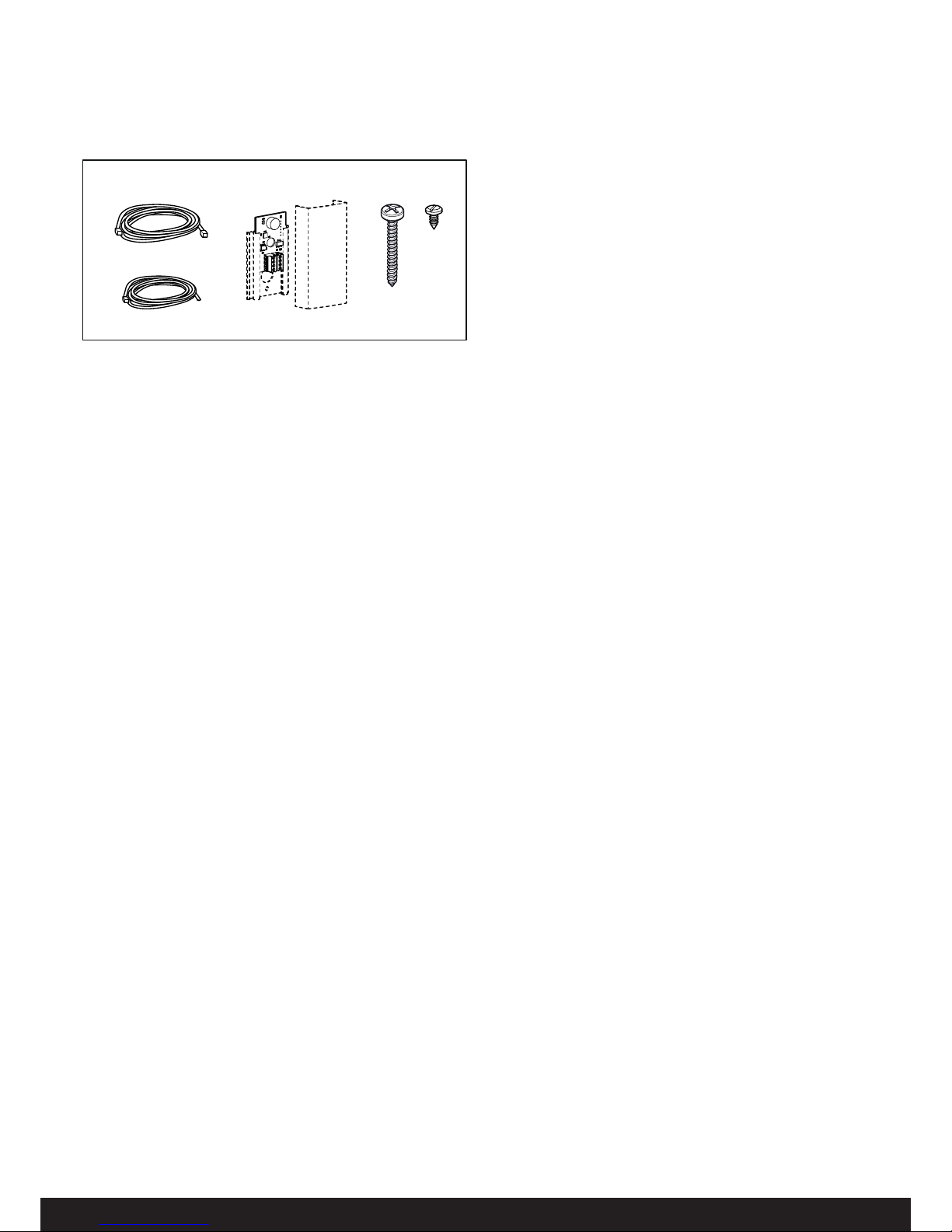
Fig 1: Delar som medföljer Tylarium Elite
1. Synkkabel, RJ10 2P4C, kabellängd 3m x 1 st
2. Kabel mellan aggregat och fukt- och tempsensor, RJ10
4P4C, kabellängd 4 m x 1 st (värmebeständig)
3. Fukt- och tempsensor (Sensorkåpa - medföljer bastuaggregat / reläbox)
4. Skruv B6x32 x 2 st
5. Skruv B4x6,5 x2 st
Kontakta återförsäljare om någon del saknas.
Bild E, G, H, I, K – kopplingsschema (se även tabell 1).
(Bastuaggregat typ Sense Commercial/Expression och ånggenerator typ Steam Commercial/Steam Home med manöverpanel typ
Elite).
1 = bastuaggregat. 2 = fukt och temperatursensor. 3 = manöverpanel Elite. 4 = eventuell extern on/off -brytare. 6 = reläbox
Commercial/Commercial Lite. 7 = ånggenerator.
Kontrollera på bastuaggregatets och på ånggeneratorns dataskylt
att anslutning sker till rätt spänning.
Glöm inte att jorda!
Bild F, J – kopplingsschema (se även tabell 1).
(Bastuaggregat typ Sense Elite och ånggenerator typ Steam
Commercial/Steam Home med manöverpanel typ Elite).
1 = bastuaggregat. 2 = fukt och temperatursensor.3 = manöverpanel Elite. 4 = eventuell extern on/off -brytare. 7 = ånggenerator.
Kontrollera på bastuaggregatets och på ånggeneratorns dataskylt
att anslutning sker till rätt spänning.
Glöm inte att jorda!
Reläbox (RB Commercial och RB Commercial Lite)
(Reläbox används ej till Sense Elite aggregat).
Monteras utanför och på obegränsat avstånd från tylariet i ett
svalt och ventilerat utrymme. Reläboxen får inte placeras närmare
än 1 meter från Elite-panelen.
Placering av termistor, fukt och temperatursensor.
Montera sensorn på väggen se Bild A, B, C, D (ej ovanför bastuaggregatet).
Placera sensorn så, att den varken direkt eller indirekt kan träff as
av ångstrålen. Termistorledningen kan förlängas utanför rummet
med skärmad svagströmsledning (4-ledare).
Montera sensorn på väggen se Fig 5. Termistorledningen kan
även dras igenom väggen, se Fig 6. OBS! Täta eventuella hål i
väggen bakom sensorn.
Belysning.
Anslut belysningen enligt kopplingschema.
Extern
ON/OFF-brytare (tillval, artikelnummer 9090 8047,
dörrkontakt krävs för funktion)
Den externa ON/OFF-brytaren placeras på valfri plats utanför
bastun, dock inte för långt ifrån bastuaggregatet så att det orsakar
spänningsfall i kabel. Spänningsfall påverkar indikationsled för
aggregatets status.
För mer information, se instruktioner som medföljer manöverpanelen och externbrytaren.
Dörrkontakt (tillval)
Dörrkontakt är ett krav (endast region EU) för att kunna använda
Elite-panelens kalenderfunktion samt fjärrstyra bastun via externbrytare, mobilapplikation eller PC-applikation.
Se instruktioner som medföljer manöverpanelen.
Anslutning till dator eller mobilapp (dörrkontakt krävs för
funktion).
Anslutning till dator sker via Elite panelens Wifi funktion och Tylö
PC app som fi nns för nedladdning (www.tylo.com\Elite). Mobilapp
fi nns att ladda ner via Google play och Appstore. För instruktion
se manöverpanelens och PC appens manualer.
Bild L - DIP-switch inställningar.
När fl era enheter skall kopplas samman skall en av dem ställas
in till att vara ”Primär” och vara den som styr de andra enheterna.
De andra enheterna ställs då in till att vara ”Sekundär”. Används
bastuaggregatet Sense Elite skall det ställas till ”Primär” och
används en reläbox skall den ställas till ”Primär”. Ånggeneratorn
sätts alltid som sekundär.
INSTALLATION TYLARIUM
Denna anvisning läses tillsammans med monteringsanvisning
som medföljer bastuaggregat resp. ånggenerator.
Delar
Kontrollera att följande delar fi nns med i emballaget:
Page 4
2
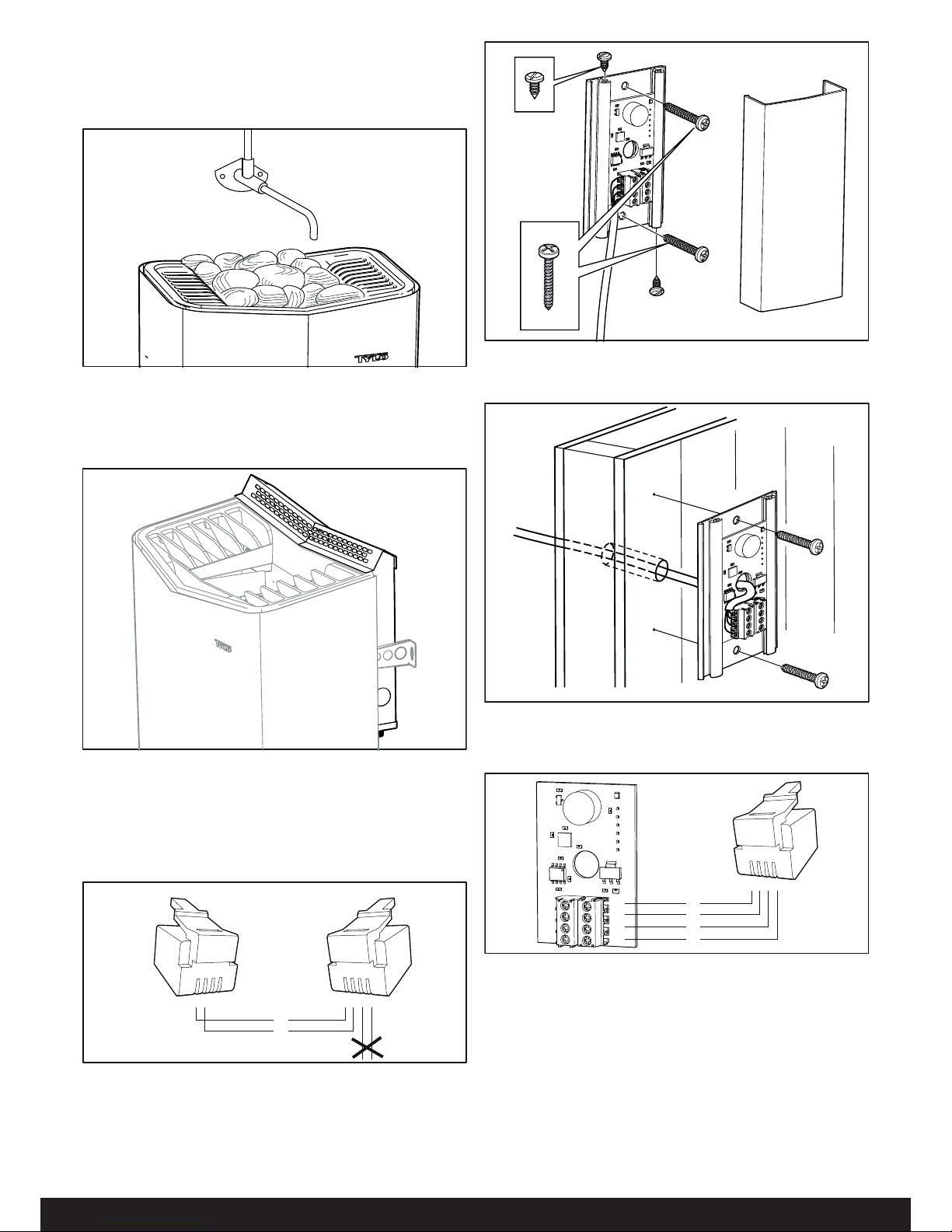
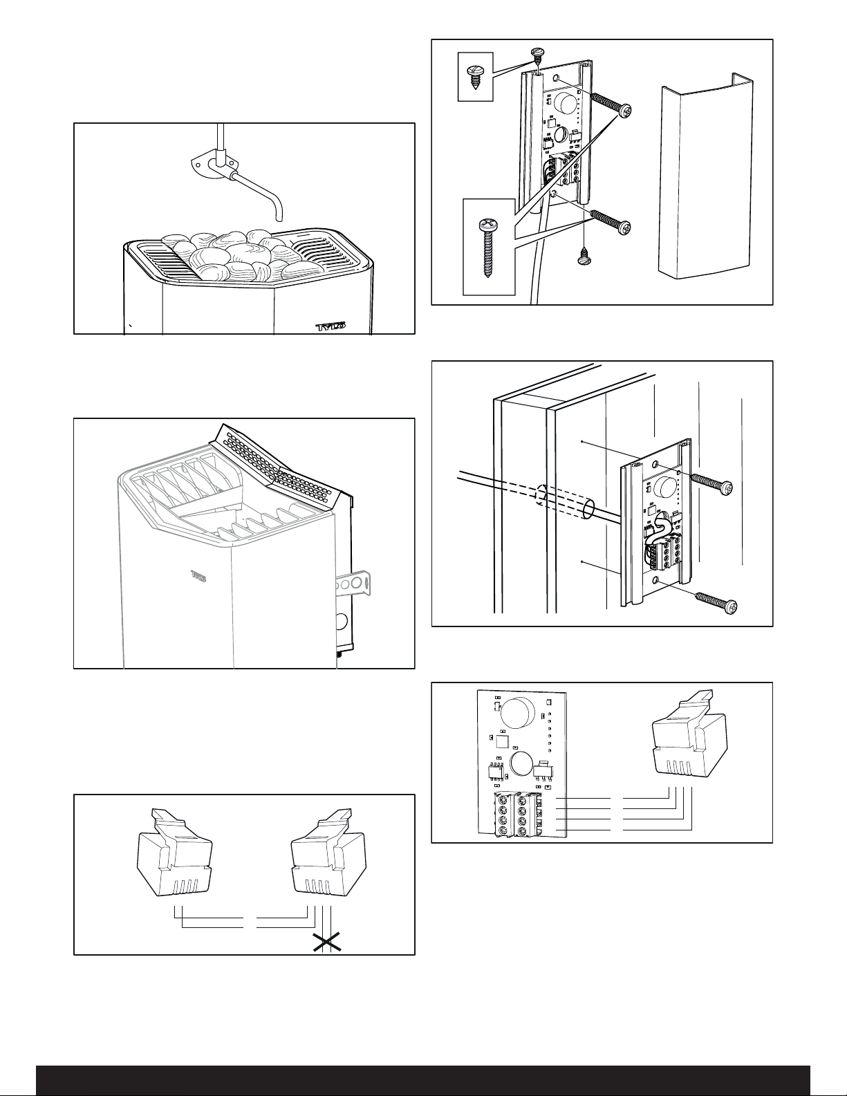
Fig 5: Montering av fukt- och tempsensorn. Kabeln inne i bastun
måste vara värmebeständig.
Fig 6: Ledningsdragning genom vägg. Täta eventuella hål i väggen bakom sensorn.
Fig 4: Synkkabel. OBS! Endast 2-ledare.
123
4
123
4
A
B
Synkkabel
Mellan ånggenerator och reläbox/bastuaggregat skall en speciell
synkkabel kopplas (RJ10 2P4C A/B). Den medföljer i Tylariumpaketet. Kabeln kontakteras om enligt fi gur 4 om den exempelvis
behöver kortas av.
Fig 2: Ångmunstycke
Fig 3: Ångfördelare
Ångfördelare Tylarium (tillval).
Ångfördelaren passar aggregaten Sense Commercial 10-16-20.
Se anvisning som medföljer ångfördelaren.
Ångmunstycke Tylarium (tillval).
Ångmunstycket används till Sense Commercial 6-8, Sense Elite
6-8 och Expression 10. Om ångmunstycket monteras ovanför
aggregat som hänger på väggkonsoler bör röret kapas ca 40mm,
se anvisning som medföljer ångmunstycket.
Fig 7: Inkoppling av fukt- och tempsensor
R=Röd, G=Grön, W=Vit, B=Svart
A
B
11
12
123
4
R
G
W
B
Page 5

3
BRUKSANVISNING TYLARIUM
Vid uppstart av Tylarium skall alltid ånggeneratorn startas (strömsättas) först, därefter bastuaggregat eller reläbox. Det behöver
inte gå längre tid mellan starttillfällena, någon/några sekunder är
lagom.
Om extrautrustning (till exempel doftpump eller extra belysning)
skall användas kopplas den tillavsedda plintar i reläboxen (AUX)
Inställning av temperatur och fukt.
Temperatur- och fuktinställning är hopkopplad. Det innebär att om
man ökar temperaturen över vissa värden så kommer samtidigt
inställd fuktnivå att minska, och tvärt om.
Vid för hög rumstemperatur kommer inte ånggeneratorn att producera ånga.
För övriga funktioner se Elite manöverpanelens manual samt
bruksanvisning för bastuaggregat och ånggenerator.
TYLARIUM
Tylarium erbjuder bastubad i alla dess former. Torrbastu, Våtbastu och Ångbastu. Eftersom den relativa luftfuktigheten ibland är
högre än vid traditionella bastubad bör nedanstående punkter
beaktas.
• Har bastun fönster i dörr eller vägg, skall dörr- resp fönsterfodrets hela nedre list strykas med båtfernissa och skarven
mellan glas och list tätas med våtrumssilikon. På så sätt
förhindras eventuell kondens på glasytorna att tränga ner i
skarven.
• Lackera tröskeln (om sådan fi nns) och dörrhandtagen ett par
gånger med båtfernissa, så behålls träets fi nish och rengöringen av bastun blir mycket enklare. Bastulavar dekorraster
och ryggstöd inoljas på båda sidor med Tylö bastuolja.
OBS! Allt övrigt trä inne i bastun skall vara obehandlat.
Denna bruksanvisning bör sparas!
Vid eventuella problem, kontakta inköpsstället.
© Eftertryck, helt eller delvis, är förbjudet utan Tylös skriftliga tillstånd. Rätt
till ändringar i material, konstruktion och design förbehålls.
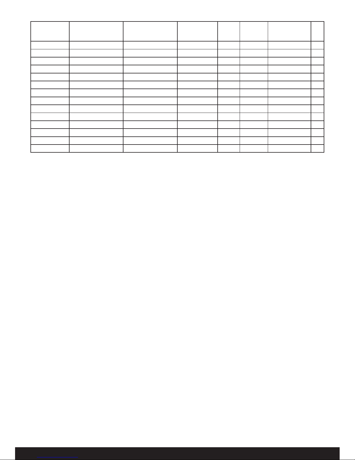
Tabell 1: Kombinationstabell
Spänning Bastuaggregat kW Ånggenerator Reläbox Kontroll-
panel
Bastuvolym
min/max m³
Tillval Bild
400-415 V 3N~ Sense Commercial 10 Steam Commercial 9 Commercial Elite 10-18 Ångfördelare E
400-415 V 3N~ Expression 10 Steam Commercial 9 Commercial Elite 10-18 Ångmunstycke E
400-415 V 3N~ Sense Elite 6 Steam Home 6 - Elite* 4-8 Ångmunstycke F
400-415 V 3N~ Sense Elite 8 Steam Home 6 - Elite* 6-12 Ångmunstycke F
400-415 V 3N~ Sense Commercial 16 Steam Commercial 12 Commercial Elite 15-35 Ångfördelare G
400-415 V 3N~ Sense Commercial 20 Steam Commercial 12 Commercial Elite 22-43 Ångfördelare G
400-415 V 3N~ Sense Commercial 6 Steam Home 6 Commercial Lite Elite 4-8 Ångmunstycke H
400-415 V 3N~ Sense Commercial 8 Steam Home 6 Commercial Lite Elite 6-12 Ångmunstycke H
200-240 V 3~ Sense Commercial 10 Steam Commercial 9 Commercial Elite 10-18 Ångfördelare I
200-240 V 3~ Expression 10 Steam Commercial 9 Commercial Elite 10-18 Ångmunstycke I
200-240 V 3~ Sense Elite 6 Steam Home 6 - Elite* 4-8 Ångmunstycke J
200-240 V 3~ Sense Elite 8 Steam Home 6 - Elite* 6-12 Ångmunstycke J
200-240 V~ Sense Commercial 10 Steam Commercial 9 Commercial Elite 10-18 Ångfördelare K
200-240 V~ Expression 10 Steam Commercial 9 Commercial Elite 10-18 Ångmunstycke K
* Elite-panelen medföljer Sense Elite
Vid Tylarium krävs tillbehör ”Tylarium Elite”, artikelnummer 7101 6000.
Page 6

4
TYLARIUM INSTALLATION
Read these instructions together with the installation instructions
that came with the sauna heater in regard to the steam generator.
Figures A and M – TYLARIUM
(Sauna heater type Sense Commercial 10-16-20 and steam generator type Commercial.)
1 = sauna heater. 2 = humidity and temperature sensor. 3 = Elite
control panel. 4 = external on/off switch (option). 5 = distribution
board. 6 = Commercial relay box. 7 = steam generator.
Figures B and N – TYLARIUM
(Sauna heater type Sense Commercial 6-8 and steam generator
type Home.)
1 = sauna heater. 2 = humidity and temperature sensor. 3 = Elite
control panel. 4 = external on/off switch (option). 5 = distribution
board. 6 = Commercial Lite relay box. 7 = steam generator.
Figures C and O – TYLARIUM
(Sauna heater type Sense Expression 10 and steam generator
type Commercial.)
1 = sauna heater. 2 = humidity and temperature sensor. 3 = Elite
control panel. 4 = external on/off switch (option). 5 = distribution
board. 6 = Commercial relay box. 7 = steam generator.
Figures D and P – TYLARIUM
(Sauna heater type Sense Elite 6-8 and steam generator type
Home.)
1 = sauna heater. 2 = humidity and temperature sensor. 3 = Elite
control panel. 4 = external on/off switch (option). 5 = distribution
board. 7 = steam generator.
3
2
145
Figure 1: Parts that come with the Tylarium Elite
1. 1 x synchronisation cable, RJ10 2P4C, cable length 3 m
2. 1 x cable between heater and humidity/temperature sensor,
RJ10 4P4C, cable length 4 m (heat-resistant)
3. Humidity and temperature sensor (Sensor cover - supplied
with heater / relay box)
4. 2 x B6x32 screws
5. 2 x B4x6.5 screws
Contact your dealer if anything is missing.
Figures E, G, H, I and K – wiring diagram (see also Table 1).
(Sauna heater type Sense Commercial/Expression and steam generator type Steam Commercial/Steam Home with control panel
type Elite.)
1 = sauna heater. 2 = humidity and temperature sensor. 3 = Elite
control panel. 4 = external on/off switch (option). 6 = relay box
Commercial/Commercial Lite. 7 = steam generator.
Check the data plates on the sauna heater and steam generator
to ensure they are connected to the correct voltage.
Don't forget – the installation must be earthed!
Figures F and J – wiring diagram (see also Table 1).
(Sauna heater type Sense Elite and steam generator type Steam
Commercial/Steam Home with control panel type Elite.)
1 = sauna heater. 2 = humidity and temperature sensor. 3 = Elite
control panel. 4 = external on/off switch (option). 7 = steam generator.
Check the data plates on the sauna heater and steam generator
to ensure they are connected to the correct voltage.
Don't forget – the installation must be earthed!
Relay box (RB Commercial and RB Commercial Lite)
(Relay box is not used with the Sense Elite heater).
Installed outside and at any distance from the Tylarium in a cool,
ventilated place. The relay box must be positioned no closer than
1 metre from the Elite panel.
Positioning of thermistor, humidity and temperature sensor
Install the sensor on the wall see Fig A, B, C, D (not above the
sauna heater).
Position the sensor so that it cannot be hit, either directly or
indirectly, by the steam jet. The thermistor wire can be extended
outside of the room using a shielded low voltage wire (4-core).
Install the sensor on the wall; see Figure 5. The thermistor wire
may also be passed through the wall; see Figure 6. NB: Seal any
holes in the wall behind the sensor.
Lighting
Connect the lighting according to the wiring diagram.
External
ON/OFF switch (option, item no. 9090 8047, door
contact needed for function)
The external ON/OFF switch can be positioned anywhere outside
the sauna, but not too far from the heater, to avoid voltage loss in
the cable. Voltage loss aff ects the LED indicator for the heater's
status.
For more information, see the instructions supplied with the control panel and external switch.
Door contact (option)
The door contact is necessary (only for the EU region) to be able
to use the Elite panel’s calendar function, plus remote control the
sauna via external switch, mobile or PC apps.
See the instructions supplied with the control panel.
Connecting to a computer or mobile app (door contact
needed for function)
Connect to a computer via the Elite panel's Wi-Fi function and the
Tylö PC app, which is available for download (www.tylo.com\Elite). The mobile app can be downloaded via Google Play and the
App Store. For instructions, see the manuals for the control panel
and the PC app.
Figure L – DIP switch settings
When more than one unit is connected together, one of them
must be set up to be the “Primary” unit, and is the one which controls the others. The other units are then set up to be “Secondary”. If you are using the Sense Elite sauna heater, this must be set
as “Primary”. If a relay box is used, this must be set as “Primary”.
The steam generator is always set as “Secondary”.
TYLARIUM INSTALLATION
Read these instructions together with the installation instructions
that came with the sauna heater in regard to the steam generator.
Parts
Check that the following parts are included in the packaging:
Page 7
5
Figure 5: Installing the humidity and temperature sensor. The
cable inside the sauna must be heat-resistant.
Figure 6: Passing a wire through a wall. Seal any holes in the wall
behind the sensor.
Figure 4: Synchronisation cable. NOTE! Only 2-core.
123
4
123
4
A
B
Synchronisation cable
A special synchronisation cable (RJ10 2P4C A/B) must be
connected between the steam generator and relay box/sauna
aggregate. This is included in the Tylarium packet. The cable is
reconnected in accordance with Figure 4 if it needs to be shortened, for example.
Figure 2: Steam nozzle
Figure 3: Steam distributor
Tylarium steam distributor (option).
The steam distributor works with Sense Commercial 10-16-20
heaters. See instructions supplied with the steam distributor.
Tylarium steam nozzle (option).
The steam nozzle is used with Sense Commercial 6-8, Sense
Elite 6-8 and Expression 10. If the steam nozzle is installed above
a heater which is hanging on wall brackets, the pipe should be
shortened by about 40 mm; see instructions supplied with the
steam nozzle.
A
B
11
12
123
4
R
G
W
B
Fig 7: Connecting the humidity- and temperature sensor
R=Red, G=Green, W=White, B=Black
Page 8
6
TYLARIUM USER GUIDE
When starting the Tylarium, the steam generator must always be
started (powered on) fi rst, followed by the sauna heater or relay
box. There is no need to leave a long gap between starting each
unit; a few seconds is fi ne.
If using accessories (such as a fragrance pump or additional
lighting), connect them to the appropriate terminals in the relay
box (AUX).
Setting the temperature and humidity
Temperature and humidity settings are interlinked. This means
that if you increase the temperature above a certain value, the
defi ned humidity level will fall, and vice versa.
If the room temperature is too high, the steam generator will not
produce steam.
For other functions, see the manual for the Elite control panel and
the user guide for the sauna heater and steam generator.
TYLARIUM
Tylarium off ers all kinds of saunas: dry, wet and steam saunas.
Since the relative humidity is occasionally higher than in traditional saunas, please observe the following:
• If the sauna has a window in the door or wall, treat the whole
lower moulding with spar varnish and seal the joint between
the glass and moulding with wet room silicone to prevent
any condensation on the glass surfaces from leaking into the
joint.
• Varnish the threshold (if there is one) and door handles with
two coats of spar varnish to maintain the wood's fi nish and
make it much easier to clean the sauna. Sauna benches,
decorative screens and back rests should be oiled on both
sides with Tylö sauna oil.
NB: All other wood in the sauna should be untreated.
Please keep these instructions!
In the event of problems, please contact the retailer where you purchased
the equipment.
© This publication many not be reproduced, either partly or in full, without
the written permission of Tylö. Tylö reserves the right to make changes to
materials, construction and design.
Table 1: Combination table
Voltage Sauna heater kW Steam generator Relay box Control
panel
Sauna volume min./
max. m³
Option Fi-
gu-
re
400-415 V 3N~ Sense Commercial 10 Steam Commercial 9 Commercial Elite 10-18 Steam distributor E
400-415 V 3N~ Expression 10 Steam Commercial 9 Commercial Elite 10-18 Steam nozzle E
400-415 V 3N~ Sense Elite 6 Steam Home 6 - Elite* 4-8 Steam nozzle F
400-415 V 3N~ Sense Elite 8 Steam Home 6 - Elite* 6-12 Steam nozzle F
400-415 V 3N~ Sense Commercial 16 Steam Commercial 12 Commercial Elite 15-35 Steam distributor G
400-415 V 3N~ Sense Commercial 20 Steam Commercial 12 Commercial Elite 22-43 Steam distributor G
400-415 V 3N~ Sense Commercial 6 Steam Home 6 Commercial Lite Elite 4-8 Steam nozzle H
400-415 V 3N~ Sense Commercial 8 Steam Home 6 Commercial Lite Elite 6-12 Steam nozzle H
200-240 V 3~ Sense Commercial 10 Steam Commercial 9 Commercial Elite 10-18 Steam distributor I
200-240 V 3~ Expression 10 Steam Commercial 9 Commercial Elite 10-18 Steam nozzle I
200-240 V 3~ Sense Elite 6 Steam Home 6 - Elite* 4-8 Steam nozzle J
200-240 V 3~ Sense Elite 8 Steam Home 6 - Elite* 6-12 Steam nozzle J
200-240 V~ Sense Commercial 10 Steam Commercial 9 Commercial Elite 10-18 Steam distributor K
200-240 V~ Expression 10 Steam Commercial 9 Commercial Elite 10-18 Steam nozzle K
* The Elite panel is supplied with Sense Elite.
Tylarium requires the accessory “Tylarium Elite”, item no. 7101 6000.
Page 9

7
INSTALLATION TYLARIUM
Lesen Sie diese Anleitung zusammen mit der Installationsanleitung aus dem Lieferumfang des Saunaofens/Dampferzeugers.
Abbildungen A und M – TYLARIUM
(Saunaheizung Typ Sense Commercial 10-16-20 und Dampferzeuger Typ Commercial.)
1 = Saunaheizung. 2 = Feuchtigkeits- und Temperaturfühler. 3 =
Bedienpanel Elite. 4 = externer Ein/Aus-Schalter (optional) 5 =
Verteilertafel. 6 = Relaiskasten Commercial. 7 = Dampferzeuger.
Abbildungen B und N – TYLARIUM
(Saunaheizung Typ Sense Commercial 6-8 und Dampferzeuger
Typ Home.)
1 = Saunaheizung. 2 = Feuchtigkeits- und Temperaturfühler. 3 =
Bedienpanel Elite. 4 = externer Ein/Aus-Schalter (optional) 5 =
Verteilertafel. 6 = Relaiskasten Commercial Lite. 7 = Dampferzeuger.
Abbildungen C und O – TYLARIUM
(Saunaheizung Typ Sense Expression 10 und Dampferzeuger
Typ Commercial.)
1 = Saunaheizung. 2 = Feuchtigkeits- und Temperaturfühler. 3 =
Bedienpanel Elite. 4 = externer Ein/Aus-Schalter (optional) 5 =
Verteilertafel. 6 = Relaiskasten Commercial. 7 = Dampferzeuger.
Abbildungen D und P – TYLARIUM
(Saunaheizung Typ Sense Elite 6-8 und Dampferzeuger Typ
Home.)
1 = Saunaheizung. 2 = Feuchtigkeits- und Temperaturfühler. 3 =
Bedienpanel Elite. 4 = externer Ein/Aus-Schalter (optional) 5 =
Verteilertafel. 7 = Dampferzeuger.
Abbildungen E, G, H, I und K – Schaltplan (siehe auch Tabelle
1).
(Saunaheizung Typ Sense Commercial/Expression und Dampferzeuger Typ Steam Commercial/Steam Home mit Bedienpanel Typ
Elite.)
1 = Saunaheizung. 2 = Feuchtigkeits- und Temperaturfühler. 3 =
Bedienpanel Elite. 4 = externer Ein/Aus-Schalter (optional) 6 =
Relaiskasten Commercial/Commercial Lite. 7 = Dampferzeuger.
3
2
145
Abbildung 1: Im Lieferumfang des Tylariums Elite enthaltene Teile
1. 1 x Synchronisationskabel, RJ10 2P4C, Kabellänge 3 m
2. 1 x Kabel zwischen Heizung und Feuchtigkeits-/Temperaturfühler, RJ10 4P4C, Kabellänge 4 m (hitzebeständig)
3. Feuchtigkeits- und Temperaturfühler (Sensorabdeckung – mit
mit saunaheizung / relaiskasten eingeschlossen)
4. 2 x B6x32-Schrauben
5. 2 x B4x6,5-Schrauben
Wenden Sie sich an Ihren Händler, falls etwas fehlt.
Prüfen Sie die Typenschilder der Saunaheizung und des Dampferzeugers, um sicherzustellen, dass sie an die richtige Spannung
angeschlossen sind.
Vergessen Sie nicht, die Installation zu erden!
Abbildungen F und J – Schaltplan (siehe auch Tabelle 1).
(Saunaheizung Typ Sense Elite und Dampferzeuger Typ Steam
Commercial/Steam Home mit Bedienpanel Typ Elite.)
1 = Saunaheizung. 2 = Feuchtigkeits- und Temperaturfühler. 3 =
Bedienpanel Elite. 4 = externer Ein/Aus-Schalter (optional) 7 =
Dampferzeuger.
Prüfen Sie die Typenschilder der Saunaheizung und des Dampferzeugers, um sicherzustellen, dass sie an die richtige Spannung
angeschlossen sind.
Vergessen Sie nicht, die Installation zu erden!
Relaiskasten (RB Commercial und RB Commercial Lite)
(Der Relaiskasten wird nicht für die Heizung Sense Elite verwendet.)
Wird außerhalb des Tylariums und in beliebiger Entfernung an
einem kühlen, belüfteten Ort installiert. Der Relaiskasten muss
einen Mindestabstand von 1 Meter zum Panel Elite haben.
Platzierung von Thermistor, Feuchtigkeits- und Temperaturfühler
Montieren Sie den Sensor an der Wand siehe Abbildungen A, B,
C, D (nicht über der Saunaheizung).
Platzieren Sie den Sensor so, dass er weder direkt noch indirekt
vom Dampfstrahl getroff en werden kann. Das Thermistorkabel
kann über ein Niederspannungskabel (4-adrig) aus dem Dampfbad hinausgeführt werden.
Montieren Sie den Sensor an der Wand (siehe Abbildung 5). Das
Thermistorkabel kann ebenfalls durch die Wand geführt werden
(siehe Abbildung 6). Hinweis: Dichten Sie hinter dem Sensor
befi ndliche Löcher in der Wand ab.
Beleuchtung
Schließen Sie die Beleuchtung anhand des Schaltplans an.
Externer
EIN/AUS-Schalter (optional, Artikelnr. 9090 8047,
Funktion erfordert Türkontakt)
Der externe EIN/AUS-Schalter kann überall außerhalb der Sauna
positioniert werden. Allerdings sollte der Abstand zur Heizung
nicht zu groß sein, damit die Kabelstrecke keine Spannungsverluste verursacht. Spannungsverluste beeinfl ussen die LED-Anzeige für den Heizungsstatus.
Weitere Informationen entnehmen Sie bitte der Anleitung aus dem
Lieferumfang des Bedienpanels und des externen Schalters.
Türkontakt (optional)
Der Türkontakt ist nötig (nur für die EU-Region), um die Kalenderfunktion des Elite Bedienpanels nutzen zu können und die Sauna
mit dem externen Schalter oder Mobilfunk-/PC-Apps fernzusteuern. Siehe Anleitung aus dem Lieferumfang des Bedienpanels.
Verbinden mit einem Computer oder einer mobilen App
(Funktion erfordert Türkontakt)
Der Anschluss an einen Computer erfolgt über die WLAN-Funktion des Panels Elite und die Tylö-PC-App, die zum Download bereitsteht (www.tylo.com\Elite). Die mobile App kann über Google
Play und den App Store heruntergeladen werden. Anweisungen
entnehmen Sie bitte den Handbüchern für das Bedienpanel und
die PC-App.
Abbildung L – DIP-Einstellungen
Wenn Sie mehr als eine Einheit zusammenschließen, muss eine
von ihnen als „Primäreinheit“ eingerichtet werden, die die anderen
steuert. Die anderen Einheiten werden dann als „Sekundäreinheit“ eingerichtet. Wenn Sie die Saunaheizung Sense Elite verwenden, muss diese als „Primäreinheit“ eingestellt werden. Wenn
ein Relaiskasten verwendet wird, muss dieser als „Primäreinheit“
eingestellt werden. Der Dampferzeuger wird immer als „Sekundäreinheit“ eingestellt.
INSTALLATION TYLARIUM
Lesen Sie diese Anleitung zusammen mit der Installationsanleitung aus dem Lieferumfang des Saunaofens/Dampferzeugers.
Teile
Vergewissern Sie sich, dass die Verpackung folgende Teile enthält:
Page 10

8
Abbildung 5: Installieren des Feuchtigkeits- und Temperaturfühlers. Das Kabel in der Sauna muss hitzebeständig sein.
Abbildung 6: Ziehen eines Kabels durch die Wand. Dichten Sie
hinter dem Sensor befi ndliche Löcher in der Wand ab.
Abbildung 4: Synchronisationskabel. ACHTUNG! Nur 2-adrig.
123
4
123
4
A
B
Synchronisationskabel
Zwischen dem Dampferzeuger und dem Relaiskasten/Saunaofen muss ein spezielles Synchronisationskabel (RJ10 2P4C A/B)
angeschlossen werden. Dieses ist im Lieferumfang des Tylariums
enthalten. Das Kabel wird gemäß Abbildung 4 wieder angeschlossen, wenn es z. B. gekürzt werden muss.
Abbildung 2: Dampfventil
Abbildung 3: Dampfverteiler
Dampfverteiler Tylarium (optional).
Der Dampfverteiler passt zu den Heizungen Sense Commercial
10-16-20. Siehe die Anleitung aus dem Lieferumfang des Dampfverteilers.
Dampfventil Tylarium (optional).
Das Dampfventil wird zusammen mit Sense Commercial 6-8,
Sense Elite 6-8 und Expression 10 verwendet. Wenn das Dampfventil über einer Heizung installiert wird, die an Wandhalterungen
hängt, sollte das Rohr um etwa 40 mm gekürzt werden; siehe die
Anleitung aus dem Lieferumfang des Dampfventils.
A
B
11
12
123
4
R
G
W
B
Abbildung 7: Anschließen des Feuchtigkeits- und Temperaturfühlers
R=Rot, G=Grün, W=Weiß, B=Schwarz
Page 11

9
BEDIENUNGSANLEITUNG TYLARIUM
Beim Starten des Tylariums muss stets als Erstes der Dampferzeuger gestartet (eingeschaltet) werden, gefolgt von der Saunaheizung oder dem Relaiskasten. Es ist kein großer Zeitabstand
zwischen dem Starten der einzelnen Einheiten erforderlich; ein
paar Sekunden sind ausreichend.
Bei Verwendung von Zubehör (wie z. B. eine Duftkonzentratpumpe oder Zusatzbeleuchtung) schließen Sie dieses an den entsprechenden Anschlüssen im Relaiskasten an (AUX).
Einstellen von Temperatur und Feuchtigkeit
Die Temperatur- und Feuchtigkeitseinstellungen sind miteinander
verknüpft. Dies bedeutet, dass, wenn Sie die Temperatur über
einen bestimmten Wert hinaus erhöhen, das eingestellte Feuchtigkeitsniveau fällt, und umgekehrt.
Bei zu hoher Raumtemperatur erzeugt der Dampferzeuger keinen
Dampf.
Zu anderen Funktionen siehe das Handbuch für das Bedienpanel
Elite und die Bedienungsanleitung für die Saunaheizung und den
Dampferzeuger.
TYLARIUM
Das Tylarium bietet alle Arten von Saunas: Trockensauna,
Feuchtsauna und Dampfbad. Da die relative Feuchtigkeit gelegentlich höher ist als in traditionellen Saunas, beachten Sie bitte
Folgendes:
• Wenn die Sauna ein Fenster in der Tür oder Wand hat, behandeln Sie deren gesamte untere Leiste mit Bootslack und
dichten Sie die Ritze zwischen Glas und Leiste mit Feuchtraumsilikon ab, um zu verhindern, dass Kondensation auf
den Glasoberfl ächen in die Ritze gelangt.
• Lackieren Sie die Schwelle (sofern vorhanden) und die Türgriff e mit zwei Schichten Bootslack, um die Holzmaserung zu
erhalten und das Reinigen der Sauna erheblich zu erleichtern. Saunabänke, Zierverkleidungen und Rückenlehnen
sollten beidseitig mit Tylö-Saunaöl geölt werden.
Hinweis: Alles übrige Holz in der Sauna sollte unbehandelt sein.
Bitte bewahren Sie diese Anleitung auf!
Sollten Probleme auftreten, wenden Sie sich an den Händler, bei dem Sie
das Produkt erworben haben.
© Diese Anleitung darf ohne die vorherige schriftliche Genehmigung von
Tylö weder ganz noch teilweise vervielfältigt werden. Tylö behält sich das
Recht vor, Änderungen an Material, Bauweise und Design vorzunehmen.
Tabelle 1: Kombinationstabelle
Spannung Saunaheizung kW Dampferzeuger Relaiskasten Bedien-
panel
Saunavolumen min./
max. m³
Option Ab-
bil-
dung
400-415 V 3N~ Sense Commercial 10 Steam Commercial 9 Commercial Elite 10-18 Dampfverteiler E
400-415 V 3N~ Expression 10 Steam Commercial 9 Commercial Elite 10-18 Dampfventil E
400-415 V 3N~ Sense Elite 6 Steam Home 6 - Elite* 4-8 Dampfventil F
400-415 V 3N~ Sense Elite 8 Steam Home 6 - Elite* 6-12 Dampfventil F
400-415 V 3N~ Sense Commercial 16 Steam Commercial 12 Commercial Elite 15-35 Dampfverteiler G
400-415 V 3N~ Sense Commercial 20 Steam Commercial 12 Commercial Elite 22-43 Dampfverteiler G
400-415 V 3N~ Sense Commercial 6 Steam Home 6 Commercial Lite Elite 4-8 Dampfventil H
400-415 V 3N~ Sense Commercial 8 Steam Home 6 Commercial Lite Elite 6-12 Dampfventil H
200-240 V 3~ Sense Commercial 10 Steam Commercial 9 Commercial Elite 10-18 Dampfverteiler I
200-240 V 3~ Expression 10 Steam Commercial 9 Commercial Elite 10-18 Dampfventil I
200-240 V 3~ Sense Elite 6 Steam Home 6 - Elite* 4-8 Dampfventil J
200-240 V 3~ Sense Elite 8 Steam Home 6 - Elite* 6-12 Dampfventil J
200-240 V~ Sense Commercial 10 Steam Commercial 9 Commercial Elite 10-18 Dampfverteiler K
200-240 V~ Expression 10 Steam Commercial 9 Commercial Elite 10-18 Dampfventil K
* Das Panel Elite gehört zum Lieferumfang von Sense Elite.
Das Tylarium erfordert das Zubehör „Tylarium Elite“, Artikelnr. 7101 6000.
Page 12

10
INSTALLATION DU TYLARIUM
Lisez ces instructions ainsi que les instructions d'installation du
poêle de sauna relatif au générateur de vapeur.
Illustration A et M – TYLARIUM
(Poêle de sauna type Sense Commercial 10-16-20 et générateur
de vapeur type Commercial.)
1 = poêle de sauna. 2 = capteur d'humidité et de température. 3
= panneau de commande Elite. 4 = interrupteur ON/OFF externe
(en option). 5 = panneau de distribution. 6 = boîte de relais Commercial. 7 = générateur de vapeur.
Illustration B et N – TYLARIUM
(Poêle de sauna type Sense Commercial 6-8 et générateur de
vapeur type Home.)
1 = poêle de sauna. 2 = capteur d'humidité et de température. 3
= panneau de commande Elite. 4 = interrupteur ON/OFF externe
(en option). 5 = panneau de distribution. 6 = boîte de relais Commercial Lite. 7 = générateur de vapeur.
Illustration C et O – TYLARIUM
(Poêle de sauna type Sense Expression 10 et générateur de
vapeur type Commercial.)
1 = poêle de sauna. 2 = capteur d'humidité et de température. 3
= panneau de commande Elite. 4 = interrupteur ON/OFF externe
(en option). 5 = panneau de distribution. 6 = boîte de relais Commercial. 7 = générateur de vapeur.
Illustration D et P – TYLARIUM
(Poêle de sauna type Sense Elite 6-8 et générateur de vapeur
type Home.)
1 = poêle de sauna. 2 = capteur d'humidité et de température. 3
= panneau de commande Elite. 4 = interrupteur ON/OFF externe (en option). 5 = panneau de distribution. 7 = générateur de
vapeur.
Illustrations E, G, H, I et K – schéma de branchement (voir
également tableau 1).
(Poêle de sauna type Sense Commercial / Expression et générateur de vapeur type Steam Commercial / Steam Home avec
panneau de commande type Elite.)
1 = poêle de sauna. 2 = capteur d’humidité et de température. 3
= panneau de commande Elite. 4 = interrupteur ON/OFF externe
(en option). 6 = boîte de relais Commercial / Commercial Lite. 7 =
générateur de vapeur.
3
2
145
Illustration 1 : pièces entrant dans la composition du Tylarium Elite
1. 1 câble de synchronisation, RJ10 2P4C, longueur de câble 3 m
2. 1 câble entre le poêle et le capteur d'humidité / de température, RJ10 4P4C, longueur de câble 4 m (résistant à la chaleur)
3. Capteur d'humidité et de température (Couvercle de la sonde fourni avec poêle de sauna / boîte de relais)
4. 2 vis B6 x 32
5. 2 vis B4 x 6.5
Contactez votre revendeur s'il manque une pièce quelconque.
Vérifi ez les plaques signalétiques sur le poêle de sauna et le générateur de vapeur pour vous assurer qu'ils sont connectés avec
la bonne tension.
N'oubliez pas que l'installation doit être mise à la terre !
Illustrations F et J – schéma de branchement (voir également
tableau 1).
(Poêle de sauna type Sense Elite et générateur de vapeur type
Steam Commercial / Steam Home avec panneau de commande
type Elite.)
1 = poêle de sauna. 2 = capteur d'humidité et de température. 3
= panneau de commande Elite. 4 = interrupteur ON/OFF externe
(en option). 7 = générateur de vapeur.
Vérifi ez les plaques signalétiques sur le poêle de sauna et le générateur de vapeur pour vous assurer qu'ils sont connectés avec
la bonne tension.
N'oubliez pas que l'installation doit être mise à la terre !
Boîte de relais (RB Commercial et RB Commercial Lite)
(La boîte de relais n'est pas utilisée avec le poêle Sense Elite).
Installée à l'extérieur et à une quelconque distance du Tylarium,
dans un endroit frais et aéré. La boîte de relais ne doit pas être
positionnée à moins d'1 mètre du panneau Elite.
Emplacement de la thermistance, capteur d'humidité et de
température
Installez la sonde sur le mur ; voir illustration A, B, C, D (pas
au-dessus du poêle de sauna).
Positionnez le capteur de sorte qu'il ne puisse pas être touché,
directement ou indirectement, par le jet de vapeur. Le conducteur
de thermistance peut être prolongé à l'extérieur de la pièce à
l'aide d'un câble basse tension isolé (4 âmes).
Installez le capteur sur le mur ; voir illustration 5. Le conducteur
de thermistance peut également traverser la cloison ; voir illustration 6. Remarque : bouchez tous les trous dans le mur derrière le
capteur.
Éclairage
Connectez l'éclairage conformément au schéma de raccordement.
Interrupteur
ON/OFF externe (en option, réf. 9090 8047, con-
tacteur de porte requis pour la fonction)
L'interrupteur ON/OFF externe peut être positionné n'importe où
à l'extérieur du sauna, mais pas trop loin du poêle, pour éviter la
perte de tension dans le câble. La perte de tension aff ecte l'indicateur LED de l'état du poêle.
Pour plus d'informations, consultez les instructions fournies avec
le panneau de commande et l'interrupteur externe.
Contacteur de porte (option)
Le contacteur de porte est nécessaire (unique région de l’Union
européenne) pour pouvoir utiliser la fonction Calendrier du panneau Elite, ainsi que pour commander le sauna à distance via un
interrupteur extérieur ou des applications pour téléphone portable
ou PC. Consultez les instructions fournies avec le panneau de
commande.
Connexion à un ordinateur ou une application mobile (contacteur de porte requis pour la fonction)
Connectez-vous à un ordinateur via la fonction Wi-Fi du panneau
Elite et l'application PC Tylö que vous pouvez télécharger sur
www.tylo.com\Elite. L'application mobile est disponible sur Google
Play et App Store. Pour les instructions, consultez les manuels du
panneau de commande et de l'application PC.
Illustration L – paramètres du commutateur DIP
Lorsque plusieurs unités sont connectées ensemble, l'une d'elles
doit être défi nie comme unité « primaire » et commandera les autres. Les autres unités sont défi nies comme « secondaires ». Si
vous utilisez le poêle de sauna Sense Elite, celui-ci doit être défi ni
comme « primaire ». Si une boîte de relais est utilisée, celle-ci
doit être défi nie comme « primaire ». Le générateur de vapeur est
toujours défi ni comme « secondaire ».
INSTALLATION DU TYLARIUM
Lisez ces instructions ainsi que les instructions d'installation du
poêle de sauna relatif au générateur de vapeur.
Pièces
Vérifi ez que tous les éléments suivants se trouvent bien dans
l'emballage :
Page 13

11
Illustration 5 : montage du capteur d'humidité et de température.
Le câble à l'intérieur du sauna doit être résistant à la chaleur.
Illustration 6 : passer un fi l à travers une cloison. Bouchez tous
les trous dans le mur derrière le capteur.
Illustration 4 : câble de synchronisation. REMARQUE! Seulement
2-fi ls.
123
4
123
4
A
B
Câble de synchronisation
Un câble de synchronisation spécial (RJ10 2P4C A/B) doit être
connecté entre le générateur de vapeur et la boîte de relais / l'ensemble du sauna. Il est inclus dans le pack Tylarium. Le câble est
reconnecté conformément à l'illustration 4 s'il doit être raccourci
par exemple.
Illustration 2 : bec vapeur
Illustration 3 : distributeur de vapeur
Distributeur de vapeur Tylarium (en option).
Le distributeur de vapeur fonctionne avec les poêles Sense
Commercial 10-16-20. Consultez les instructions fournies avec le
distributeur de vapeur.
Bec vapeur Tylarium (en option).
Le bec vapeur est utilisé avec Sense Commercial 6-8, Sense Elite
6-8 ou Expression 10. Si le bec vapeur est installé au-dessus d'un
poêle qui est suspendu sur des supports muraux, le tuyau devra
être raccourci d'environ 40 mm ; voir instructions fournies avec le
bec vapeur.
A
B
11
12
123
4
R
G
W
B
Illustration 7 : Raccordement de la sonde d'humidité et de
température.
R=rouge, G=vert, W=blanc, B=noir
Page 14

12
NOTICE D'UTILISATION DU TYLARIUM
Au démarrage du Tylarium, le générateur de vapeur doit toujours
être lancé (mis en marche) en premier, suivi par le poêle de sauna ou la boîte de relais. Il n'est pas nécessaire d'attendre longtemps entre le démarrage de chaque unité, quelques secondes
suffi sent.
Dans le cas d'utilisation d'accessoires (un diff useur de senteurs
ou un éclairage supplémentaire par exemple), connectez-les aux
bornes appropriées de la boîte de relais (AUX).
Régler la température et l'humidité
Le réglage de la température et celui de l'humidité sont interdépendants. Cela signifi e que si vous augmentez la température au-delà d'une certaine valeur, le niveau d'humidité défi ni
chutera et inversement.
Si la température de la pièce est trop élevée, le générateur de
vapeur ne produira pas de vapeur.
Pour les autres fonctions, consultez le manuel du panneau de
commande Elite, la notice d'utilisation du poêle de sauna ou celle
du générateur de vapeur.
Conservez la présente notice d'utilisation !
En cas de problème, contactez le distributeur auprès duquel vous avez
acheté l'appareil.
© Toute reproduction, intégrale ou partielle, de la présente publication
est interdite sans l'autorisation écrite de Tylö. Tylö se réserve le droit de
procéder sans préavis à des modifi cations des matériaux, de la conception et du design.
Tableau 1 : tableau de combinaison
Tension Poêle de sauna kW Générateur de vapeur Boîte de relais Pan-
neau de
commande
Volume du
sauna mini/
maxi m³
Option Il-
lustr.
400-415 V 3N~ Sense Commercial 10 Steam Commercial 9 Commercial Elite 10-18 Distributeur
de vapeur
E
400-415 V 3N~ Expression 10 Steam Commercial 9 Commercial Elite 10-18 Bec vapeur E
400-415 V 3N~ Sense Elite 6 Steam Home 6 - Elite* 4-8 Bec vapeur F
400-415 V 3N~ Sense Elite 8 Steam Home 6 - Elite* 6-12 Bec vapeur F
400-415 V 3N~ Sense Commercial 16 Steam Commercial 12 Commercial Elite 15-35 Distributeur
de vapeur
G
400-415 V 3N~ Sense Commercial 20 Steam Commercial 12 Commercial Elite 22-43 Distributeur
de vapeur
G
400-415 V 3N~ Sense Commercial 6 Steam Home 6 Commercial Lite Elite 4-8 Bec vapeur H
400-415 V 3N~ Sense Commercial 8 Steam Home 6 Commercial Lite Elite 6-12 Bec vapeur H
200-240 V 3~ Sense Commercial 10 Steam Commercial 9 Commercial Elite 10-18 Distributeur
de vapeur
I
200-240 V 3~ Expression 10 Steam Commercial 9 Commercial Elite 10-18 Bec vapeur I
200-240 V 3~ Sense Elite 6 Steam Home 6 - Elite* 4-8 Bec vapeur J
200-240 V 3~ Sense Elite 8 Steam Home 6 - Elite* 6-12 Bec vapeur J
200-240 V~ Sense Commercial 10 Steam Commercial 9 Commercial Elite 10-18 Distributeur
de vapeur
K
200-240 V~ Expression 10 Steam Commercial 9 Commercial Elite 10-18 Bec vapeur K
* Le panneau Elite est fourni avec Sense Elite.
Tylarium requiert l'accessoire « Tylarium Elite », réf. 7101 6000.
TYLARIUM
Tylarium propose tous les types de saunas : saunas secs, humides, à vapeur. Dans la mesure où l’humidité relative est parfois
supérieure à celle des saunas traditionnels, tenez compte de ce
qui suit :
• Si le sauna dispose d’une fenêtre dans la porte ou le mur,
traitez l’ensemble du moulage inférieure avec du vernis spar
varnish et scellez les joints entre la vitre et le moulage avec
du silicone pour pièce humide afi n d’éviter que la condensation de la surface de la vitre ne coule à l’intérieur du joint.
• Vernir le seuil (le cas échéant) et les poignées de porte
avec deux couches de vernis spar varnish pour préserver la
fi nition du bois et rendre le nettoyage du sauna plus facile.
Les bancs du sauna, les paravents décoratifs et les dossiers
doivent être huilés des deux côtés avec de l’huile spéciale
sauna Tylö.
Remarque : les autres parties en bois du sauna doivent restées
non traitées.
Page 15

13
УСТАНОВКА TYLARIUM
Прочитайте данные инструкции, а также инструкции по
установке, входящие в комплект поставки нагревателя сауны,
относящиеся к парогенератору.
Рис. A и M — TYLARIUM
(Нагреватель сауны типа Sense Commercial 10-16-20 и
парогенератор типа Commercial).
1 = нагреватель сауны. 2 = датчик температуры и влажности.
3 = панель управления Elite. 4 = внешний выключатель
(опционально). 5 = распределительный щит. 6 = блок реле
Commercial. 7 = парогенератор.
Рис. B и N — TYLARIUM
(Нагреватель сауны типа Sense Commercial 6-8 и
парогенератор типа Home).
1 = нагреватель сауны. 2 = датчик температуры и влажности.
3 = панель управления Elite. 4 = внешний выключатель
(опционально). 5 = распределительный щит. 6 = блок реле
Commercial Lite. 7 = парогенератор.
Рис. C и O — TYLARIUM
(Нагреватель сауны типа Sense Expression 10 и
парогенератор типа Commercial).
1 = нагреватель сауны. 2 = датчик температуры и влажности.
3 = панель управления Elite. 4 = внешний выключатель
(опционально). 5 = распределительный щит. 6 = блок реле
Commercial. 7 = парогенератор.
Рис. D и P — TYLARIUM
(Нагреватель сауны типа Sense Elite 6-8 и парогенератор типа
Home).
1 = нагреватель сауны. 2 = датчик температуры и
влажности. 3 = панель управления Elite. 4 = внешний
выключатель (опционально). 5 = распределительный щит. 7 =
парогенератор.
Рис. E, G, H, I и K — схема электрических соединений (см.
также таблицу 1).
(Нагреватель сауны типа Sense Commercial/Expression и
парогенератор типа Steam Commercial/Steam Home с панелью
управления типа Elite).
3
2
145
Рисунок 1: Компоненты, входящие в комплект поставки
Tylarium Elite
1. 1 кабель синхронизации, RJ10 2P4C, длина кабеля: 3 м
2. 1 кабель между нагревателем и датчиком температуры и
влажности, RJ10 4P4C, длина кабеля: 4 м (термостойким)
3. Датчик температуры и влажности (Крышка датчика –
поставляется нагреватель сауны / блок реле)
4. 2 винта B6 x 32
5. 2 винта B4 x 6,5
При отсутствии какой-либо детали свяжитесь с вашим
дилером.
1 = нагреватель сауны. 2 = датчик температуры и влажности.
3 = панель управления Elite. 4 = внешний выключатель
(опционально). 6 = блок реле Commercial/Commercial Lite. 7 =
парогенератор.
Проверьте платы обработки данных на нагревателе сауны и
парогенераторе, чтобы убедиться в том, что они подключены
к подходящему напряжению.
Помните о том, что установку необходимо заземлить!
Рис. F и J — схема электрических соединений (см. также
таблицу 1).
(Нагреватель сауны типа Sense Elite и парогенератор типа
Steam Commercial/Steam Home с панелью управления типа
Elite).
1 = нагреватель сауны. 2 = датчик температуры и влажности.
3 = панель управления Elite. 4 = внешний выключатель
(опционально). 7 = парогенератор.
Проверьте платы обработки данных на нагревателе сауны и
парогенераторе, чтобы убедиться в том, что они подключены
к подходящему напряжению.
Помните о том, что установку необходимо заземлить!
Блок реле (типа Commercial и Commercial Lite)
(Блок реле не используется вместе с нагревателем Sense
Elite).
Устанавливается снаружи на любом расстоянии от устройства
Tylarium в прохладном вентилируемом месте. Блок реле
необходимо располагать на расстоянии не менее 1 метра от
панели Elite.
Расположение термистора, датчика температуры и
влажности
Установите датчик на стене, см. Рис. A, B, C и D (не выше
нагревателя сауны).
Располагайте датчик таким образом, чтобы он не вступал
в прямой или косвенный контакт со струей пара. Провод
термистора может быть удлинен и выведен за пределы
помещения посредством экранированного низковольтного
провода (4-жильного).
Установите датчик на стене (см. рис. 5). Провод термистора
также можно провести через стену (см. рис. 6). Примечание.
Герметично заделайте любые отверстия в стене за
датчиком.
Освещение
Подключите освещение согласно схеме электрических
соединений.
Внешний
выключатель (опционально, для использования
данной функции необходимо наличие, дверного контакта
арт. №: 9090 8047)
Внешний выключатель может быть расположен в любом
месте за пределами сауны, но не слишком далеко от
нагревателя во избежание потери напряжения в кабеле.
Потеря напряжения сказывается на работе светодиодного
индикатора состояния нагревателя.
Для получения дополнительной информации см.
инструкции, поставляемые с панелью управления и
внешним выключателем.
Дверной контакт (опционально)
Дверной контакт необходим (только в ЕС) для использования
функции «календарь» панели Elite, а также для удаленного
управления сауной посредством внешнего выключателя,
мобильного приложения или приложения для ПК.
См. инструкции, поставляемые с панелью управления.
Подключение к компьютеру или мобильному
приложению (для использования данной функции
необходимо наличие дверного контакта)
Подключение к компьютеру осуществляется посредством
функции Wi-Fi панели Elite и приложения Tylö для ПК, которое
доступно для загрузки (www.tylo.com\Elite). Мобильное
приложение можно загрузить из магазинов Google Play и App
Store. Инструкции см. в руководствах к панели управления и
приложению для ПК.
УСТАНОВКА TYLARIUM
Прочитайте данные инструкции, а также инструкции по
установке, входящие в комплект поставки нагревателя сауны,
относящиеся к парогенератору.
Компоненты
Убедитесь, что в комплект включены следующие компоненты:
Page 16

14
Рисунок 5: Установка датчика температуры и влажности.
Кабель внутри сауны должен быть термостойким.
Рисунок 6: Прокладка провода через стену. Герметично
заделайте любые отверстия в стене за датчиком.
Рисунок 4: Кабель синхронизации. ВНИМАНИЕ! Только
2-жильного.
123
4
123
4
A
B
Кабель синхронизации
Парогенератор и блок реле/установку для сауны необходимо
соединить специальным кабелем синхронизации (RJ10
2P4C A/B). Он входит в пакет Tylarium. Кабель повторно
подключается в соответствии с рис. 4, если, например, его
потребуется укоротить.
Рисунок 2: Паровое сопло
Рисунок 3: Парораспределитель
Парораспределитель Tylarium (опционально).
Парораспределитель работает вместе с нагревателями Sense
Commercial 10-16-20. См. инструкции, входящие в комплект
поставки парораспределителя.
Рис. L — настройки DIP-переключателя
При подключении нескольких устройств одно из них
должно быть настроено «Основным» устройством, которое
контролирует другие устройства. Другие устройства
назначаются «Дополнительными». Если используется
нагреватель сауны Sense Elite, его необходимо настроить
в качестве «Основного» устройства. Если используется
блок реле, его необходимо настроить в качестве
«Основного» устройства. Парогенератор всегда назначается
«Дополнительным» устройством.
Паровое сопло Tylarium (опционально).
Паровое сопло используется вместе с моделями Sense
Commercial 6-8, Sense Elite 6-8 и Expression 10. Если паровое
сопло устанавливается над нагревателем, навешенным на
настенных кронштейнах, трубу следует укоротить примерно
на 40 мм (см. инструкции, входящие в комплект поставки
парового сопла).
A
B
11
12
123
4
R
G
W
B
Рисунок 7: Подключение датчика температуры и
влажности
К=Красный, З=Зеленый, Б=Белый, Ч=Черный
Page 17

15
РУКОВОДСТВО ПОЛЬЗОВАТЕЛЯ TYLARIUM
При запуске устройств Tylarium сначала необходимо всегда
включать (запускать) парогенератор, а затем нагреватель
сауны или блок реле. Между включением каждого устройства
не обязательно ждать длительное время, достаточно
нескольких секунд.
При использовании дополнительных устройств (например,
дополнительного освещения или ароматизирующего
устройства) подключайте их к соответствующим клеммам в
блоке реле (AUX).
Настройка температуры и влажности
Настройки температуры и влажности взаимосвязаны.
Это означает, что при увеличении температуры сверх
определенного значения заданный уровень влажности
снизится, и наоборот.
Если температура в помещении слишком высокая,
парогенератор не будет генерировать пар.
Описание других функций см. в руководстве к панели
управления Elite и в руководстве пользователя нагревателя
сауны и парогенератора.
TYLARIUM
Tylarium предлагает все разновидности саун: сухие,
влажные и паровые сауны. Так как относительная влажность
периодически превышает влажность в обычных саунах,
обратите внимание на следующие особенности.
• Если в двери или стене сауны имеется окно,
обработайте всю нижнюю часть профиля яхтным
лаком и герметизируйте место соединения стекла и
профиля силиконом для влажных помещений, чтобы
предотвратить просачивание конденсата со стеклянных
поверхностей в место соединения.
• Покройте порог (если имеется) и дверные ручки двумя
слоями яхтного лака, чтобы сохранить финишную отделку
древесины и значительно облегчить задачу очистки
сауны. Скамьи, декоративные экраны и подголовники
в сауне следует покрыть маслом Tylö для саун с двух
сторон.
Примечание. Все остальные деревянные элементы в сауне
не следует обрабатывать.
Сохраните данную инструкцию!
В случае возникновения проблем, пожалуйста, обратитесь в магазин,
где вы приобрели установку.
© Настоящий документ не может воспроизводиться частично или
полностью без письменного разрешения Tylö. Tylö сохраняет за собой
право вносить изменения в материалы, конструкцию и дизайн.
Таблица 1: Таблица сочетаний
Напряжение Нагреватель сауны
(кВт)
Парогенератор Блок реле Панель
управления
Объем
сауны, мин/
макс м³
Опции Рис-
унок
400–415 В, 3N~ Sense Commercial 10 Steam Commercial 9 Commercial Elite 10-18 Парораспределитель E
400–415 В, 3N~ Expression 10 Steam Commercial 9 Commercial Elite 10-18 Паровое сопло E
400–415 В, 3N~ Sense Elite 6 Steam Home 6 - Elite* 4-8 Паровое сопло F
400–415 В, 3N~ Sense Elite 8 Steam Home 6 - Elite* 6-12 Паровое сопло F
400–415 В, 3N~ Sense Commercial 16 Steam Commercial 12 Commercial Elite 15-35 Парораспределитель G
400–415 В, 3N~ Sense Commercial 20 Steam Commercial 12 Commercial Elite 22-43 Парораспределитель G
400–415 В, 3N~ Sense Commercial 6 Steam Home 6 Commercial Lite Elite 4-8 Паровое сопло H
400–415 В, 3N~ Sense Commercial 8 Steam Home 6 Commercial Lite Elite 6-12 Паровое сопло H
200–240 В, 3~ Sense Commercial 10 Steam Commercial 9 Commercial Elite 10-18 Парораспределитель I
200–240 В, 3~ Expression 10 Steam Commercial 9 Commercial Elite 10-18 Паровое сопло I
200–240 В, 3~ Sense Elite 6 Steam Home 6 - Elite* 4-8 Паровое сопло J
200–240 В, 3~ Sense Elite 8 Steam Home 6 - Elite* 6-12 Паровое сопло J
200–240 В~ Sense Commercial 10 Steam Commercial 9 Commercial Elite 10-18 Парораспределитель K
200–240 В~ Expression 10 Steam Commercial 9 Commercial Elite 10-18 Паровое сопло K
* Панель Elite поставляется с Sense Elite.
Для устройства Tylarium требуется дополнительное оборудование «Tylarium Elite», арт. №: 7101 6000.
Page 18

16
INSTALACJA MODELU TYLARIUM
Zapoznaj się z niniejszą instrukcją, a także z instrukcją instalacji
dostarczoną wraz z piecem saunowym, dotyczącą wytwornicy
pary.
Rysunki A i M — TYLARIUM
(Piec saunowy typu Sense Commercial 10-16-20 i wytwornica
pary typu Commercial).
1 = piec saunowy. 2 = czujnik temperatury i wilgotności. 3 = panel
sterowania Elite. 4 = wyłącznik zewnętrzny (opcjonalny). 5 = rozdzielnica elektryczna. 6 = skrzynka przekaźnikowa Commercial. 7
= wytwornica pary.
Rysunki B i N — TYLARIUM
(Piec saunowy typu Sense Commercial 6-8 i wytwornica pary typu
Home).
1 = piec saunowy. 2 = czujnik temperatury i wilgotności. 3 = panel
sterowania Elite. 4 = wyłącznik zewnętrzny (opcjonalny). 5 = rozdzielnica elektryczna. 6 = skrzynka przekaźnikowa Commercial
Lite. 7 = wytwornica pary.
Rysunki C i O — TYLARIUM
(Piec saunowy typu Sense Expression 10 i wytwornica pary typu
Commercial).
1 = piec saunowy. 2 = czujnik temperatury i wilgotności. 3 = panel
sterowania Elite. 4 = wyłącznik zewnętrzny (opcjonalny). 5 = rozdzielnica elektryczna. 6 = skrzynka przekaźnikowa Commercial. 7
= wytwornica pary.
Rysunki D i P — TYLARIUM
(Piec saunowy typu Sense Elite 6-8 i wytwornica pary typu
Home).
1 = piec saunowy. 2 = czujnik temperatury i wilgotności. 3 = panel
sterowania Elite. 4 = wyłącznik zewnętrzny (opcjonalny). 5 = rozdzielnica elektryczna. 7 = wytwornica pary.
Rysunki E, G, H, I i K — schemat elektryczny (patrz też Tabela
1).
(Piec saunowy typu Sense Commercial/Expression i wytwornica
pary typu Steam Commercial/Steam Home z panelem sterowania
typu Elite).
3
2
145
Rysunek 1. Części oferowane w pakiecie z modelem Tylarium
Elite
1. 1 kabel synchronizacji, RJ10 2P4C, długość kabla: 3 m
2. 1 kabel między piecem a czujnikiem wilgotności i temperatury, RJ10 4P4C, długość kabla: 4 m (odporny na wysoką
temperaturę)
3. Czujnik temperatury i wilgotności (Osłona czujnika - dostarczany z piec saunowy / skrzynka przekaźnikowa)
4. 2 wkręty B6x32
5. 2 wkręty B4x6,5
Jeśli w pakiecie czegoś brakuje, skontaktuj się ze sprzedawcą.
1 = piec saunowy. 2 = czujnik temperatury i wilgotności. 3 =
panel sterowania Elite. 4 = wyłącznik zewnętrzny (opcjonalny).
6 = skrzynka przekaźnikowa Commercial/Commercial Lite. 7 =
wytwornica pary.
Sprawdź tabliczki znamionowe na piecu saunowym i wytwornicy pary, aby się upewnić, że urządzenia zostały podłączone do
właściwego napięcia.
Nie zapomnij — instalacja musi być uziemiona!
Rysunki F i J — schemat elektryczny (patrz też Tabela 1).
(Piec saunowy typu Sense Elite i wytwornica pary typu Steam
Commercial/Steam Home z panelem sterowania typu Elite).
1 = piec saunowy. 2 = czujnik temperatury i wilgotności. 3 = panel
sterowania Elite. 4 = wyłącznik zewnętrzny (opcjonalny). 7 =
wytwornica pary.
Sprawdź tabliczki znamionowe na piecu saunowym i wytwornicy pary, aby się upewnić, że urządzenia zostały podłączone do
właściwego napięcia.
Nie zapomnij — instalacja musi być uziemiona!
Skrzynka przekaźnikowa (RB Commercial i RB Commercial
Lite)
(W przypadku pieca Sense Elite skrzynka przekaźnikowa nie jest
stosowana).
Należy ją zainstalować w dowolnej odległości od sauny Tylarium,
w chłodnym miejscu z dobrą wentylacją. Skrzynka musi się znajdować co najmniej 1 metr od panelu Elite.
Umiejscowienie termistora oraz czujnika temperatury i wilgotności
Zamontuj czujnik na ścianie, patrz rys. A, B, C, i D) (ale nie nad
piecem saunowym).
Czujnik należy umiejscowić tak, aby nie padał na niego strumień
pary, pośrednio ani bezpośrednio. Okablowanie termistora można
przedłużyć poza pomieszczenie za pomocą ekranowanego przewodu niskonapięciowego (4-żyłowego).
Zamontuj czujnik na ścianie — patrz Rys. 5. Przewód termistora
można także przeprowadzić przez ścianę — patrz Rysunek 6.
Uwaga: Jeśli w ścianie za czujnikiem znajdują się jakieś otwory,
uszczelnij je.
Oświetlenie
Podłącz oświetlenie zgodnie ze schematem elektrycznym.
Zewnętrzny
wyłącznik (opcjonalny, działa ze stykiem dr-
zwiowym, nr artykułu: 9090 8047)
Wyłącznik zewnętrzny można umieścić w dowolnym miejscu poza
sauną, ale nie za daleko od pieca, ponieważ groziłoby to spadkiem napięcia w przewodzie. Spadek napięcia zakłóciłby działanie
wskaźnika LED statusu pieca.
Więcej informacji można znaleźć w instrukcjach do panelu ste-
rowania i wyłącznika zewnętrznego.
Styk drzwiowy (opcjonalny)
Styk drzwiowy jest niezbędny (tylko w regionie UE) do korzystania
z funkcji kalendarza panelu Elite, a także zdalnego sterowania
sauną za pomocą wyłącznika zewnętrznego albo aplikacji na
smartfon lub komputer.
Informacje można znaleźć w instrukcji do panelu sterującego.
Podłączanie do komputera lub do aplikacji mobilnej (działa
ze stykiem drzwiowym)
Podłączyć saunę do komputera można za pośrednictwem funkcji
Wi-Fi dostępnej na panelu Elite oraz aplikacji komputerowej
Tylö, którą można pobrać ze strony www.tylo.com\Elite. Aplikację
mobilną można pobrać z Google Play i z App Store. Instrukcje
można znaleźć w podręcznikach obsługi panelu sterowania i
aplikacji komputerowej.
INSTALACJA MODELU TYLARIUM
Zapoznaj się z niniejszą instrukcją, a także z instrukcją instalacji
dostarczoną wraz z piecem saunowym, dotyczącą wytwornicy
pary.
Części
Sprawdź, czy w opakowaniu znajdują się następujące elementy:
Page 19

17
Rysunek 5. Montaż czujnika temperatury i wilgotności. Przewód
wewnątrz sauny musi być odporny na wysoką temperaturę.
Rysunek 6. Przeprowadzanie kabla przez ścianę. Jeśli w ścianie
za czujnikiem znajdują się jakieś otwory, uszczelnij je.
Rysunek 4. Kabel synchronizacji. UWAGA! Tylko 2-żyłowego.
123
4
123
4
A
B
Kabel synchronizacji
Wytwornicę pary i skrzynkę przekaźnikową/agregat saunowy
należy połączyć specjalnym kablem synchronizacji (RJ10 2P4C
A/B). Kabel ten jest dołączony do pakietu modelu Tylarium. Jeśli
kabel ten trzeba na przykład skrócić, należy go odłączyć zgodnie
z Rysunkiem 4.
Rysunek 2. Dysza pary
Rysunek 3. Dystrybutor pary
Dystrybutor pary Tylarium (opcjonalny).
Dystrybutor pary współpracuje z piecami Sense Commercial 1016-20. Patrz instrukcja do dystrybutora pary.
Rysunek L — ustawienia przełącznika DIP
Gdy podłącza się więcej niż jedno urządzenie, jedno z nich
musi być w ustawieniach określone jako „Główne” — steruje
ono pozostałymi. Pozostałe urządzenia są wtedy w ustawieniach określane jako „Alternatywne”. Jeśli korzystasz z pieca
saunowego Sense Elite, to on musi być określony jako „Główny”.
Jeśli używana jest skrzynka przekaźnikowa, to ją należy wskazać
jako „Główną”. Wytwornicę pary należy zawsze określać jako
urządzenie „Alternatywne”.
Dysza pary Tylarium (opcjonalna).
Dysza pary występuje w modelach Sense Commercial 6-8, Sense
Elite 6-8 i Expression 10. Jeśli dysza ta jest zainstalowana nad
piecem wiszącym na wspornikach ściennych, rurę należy skrócić
o około 40 mm — patrz instrukcja dostarczona z dyszą pary.
A
B
11
12
123
4
R
G
W
B
Rysunek 7. Podłączanie czujnika temperatury / wilgotności
R=czerwony, G=zielony, W=biały, B=czarny
Page 20

18
INSTRUKCJA OBSŁUGI MODELU TYLARIUM
Uruchamiając saunę Tylarium, należy najpierw uruchomić
(włączyć) wytwornicę pary, a następnie piec saunowy lub
skrzynkę przekaźnikową. Po włączeniu pierwszego urządzenia
nie trzeba długo czekać, aby włączyć drugie — wystarczy kilka
sekund.
W przypadku korzystania z akcesoriów (takich jak pompa
zapachu lub dodatkowe oświetlenie) należy je podłączyć do odpowiednich zacisków w skrzynce przekaźnikowej (AUX).
Ustawianie temperatury i wilgotności
Ustawienia temperatury i wilgotności są ze sobą powiązane.
Oznacza to, że jeśli zwiększy się temperaturę powyżej pewnej
wartości, zdefi niowany poziom wilgotności spadnie i na odwrót.
Jeśli temperatura w pomieszczeniu jest zbyt wysoka, wytwornica
nie będzie produkować pary.
Informacje na temat innych funkcji można znaleźć w podręczniku obsługi panelu sterowania Elite oraz instrukcji obsługi pieca
saunowego i wytwornicy pary.
TYLARIUM
Tylarium oferuje różne rodzaje saun: suche, mokre i parowe. Z
uwagi na fakt, że wilgotność względna bywa niekiedy wyższa
niż w tradycyjnych saunach, należy pamiętać o następujących
zaleceniach:
• Jeśli sauna ma okno w drzwiach lub w ścianie, pomaluj cały
dolny profi l lakierem jachtowym i uszczelnij połączenie pomiędzy szkłem a profi lem za pomocą silikonu do pomieszczeń wilgotnych, aby zapobiec przenikaniu do spojenia pary
skondensowanej na powierzchniach szklanych.
• Pomaluj próg (jeśli występuje) i klamki drzwi dwiema warstwami lakieru jachtowego, aby zabezpieczyć wykończenie
drewna i znacznie ułatwić czyszczenie sauny. Ławki sauny,
ekrany dekoracyjne i oparcia dla pleców należy naolejować
po obu stronach olejem do saun Tylö.
Uwaga: Żadnych innych drewnianych elementów sauny malować
nie należy.
Proszę zachować tę instrukcję!
W przypadku problemów prosimy o kontakt ze sprzedawcą, u którego
zakupiono sprzęt.
© Ta publikacja nie może być powielana, ani w części, ani w całości,
bez pisemnej zgody fi rmy Tylö. Firma Tylö zastrzega sobie prawo do
wprowadzania zmian w materiałach, budowie i projektach.
Tabela 1. Tabela kombinacji
Napięcie Piec saunowy kW Wytwornica pary Skrzynka prze-
kaźnikowa
Panel
sterowania
Kubatura
sauny, min./
maks. m³
Opcja Rysu-
nek
400-415 V 3N~ Sense Commercial 10 Steam Commercial 9 Commercial Elite 10-18 Dystrybutor
pary
E
400-415 V 3N~ Expression 10 Steam Commercial 9 Commercial Elite 10-18 Dysza pary E
400-415 V 3N~ Sense Elite 6 Steam Home 6 - Elite* 4-8 Dysza pary F
400-415 V 3N~ Sense Elite 8 Steam Home 6 - Elite* 6-12 Dysza pary F
400-415 V 3N~ Sense Commercial 16 Steam Commercial 12 Commercial Elite 15-35 Dystrybutor
pary
G
400-415 V 3N~ Sense Commercial 20 Steam Commercial 12 Commercial Elite 22-43 Dystrybutor
pary
G
400-415 V 3N~ Sense Commercial 6 Steam Home 6 Commercial Lite Elite 4-8 Dysza pary H
400-415 V 3N~ Sense Commercial 8 Steam Home 6 Commercial Lite Elite 6-12 Dysza pary H
200–240 V 3~ Sense Commercial 10 Steam Commercial 9 Commercial Elite 10-18 Dystrybutor
pary
I
200–240 V 3~ Expression 10 Steam Commercial 9 Commercial Elite 10-18 Dysza pary I
200–240 V 3~ Sense Elite 6 Steam Home 6 - Elite* 4-8 Dysza pary J
200–240 V 3~ Sense Elite 8 Steam Home 6 - Elite* 6-12 Dysza pary J
200–240 V~ Sense Commercial 10 Steam Commercial 9 Commercial Elite 10-18 Dystrybutor
pary
K
200–240 V~ Expression 10 Steam Commercial 9 Commercial Elite 10-18 Dysza pary K
* Panel Elite jest dołączany do zestawu pieca Sense Elite.
Model Tylarium wymaga akcesorium „Tylarium Elite”, nr artykułu: 7101 6000.
Producent:
Tylö A.B. | Halmstad, Szwecja | sauny, kabiny infrared, łaźnie
parowe, prysznice | www.tylo.com
Generalny przedstawiciel TYLÖ w Polsce:
Koperfam Sp. z o.o. | ul. Olszankowa 51, PL 05-120 Legionowo
tel. +48 22 494 34 06 | info@koperfam.pl | www.koperfam.pl
Proszę zachować instrukcję!
W przypadku problemów prosimy o kontakt ze sprzedawcą, u
którego zakupiono sprzęt.
© Ta publikacja nie może być powielana, częściowo lub w całości,
bez pisemnej zgody fi rmy Tylö. Firma Tylö zastrzega sobie prawo
do wprowadzania zmian w materiałach, budowie i projektach.
Page 21

19
INSTALLATIE TYLARIUM
Lees deze instructies samen met de installatie-instructies die zijn
meegeleverd bij de saunakachel met betrekking tot de stoomgenerator.
Afbeeldingen A en M: TYLARIUM
(Saunakacheltype Sense Commercial 10-16-20 en stoomgeneratortype Commercial.)
1 = saunakachel. 2 = luchtvochtigheids- en temperatuursensor. 3
= Elite-bedieningspaneel. 4 = externe AAN/UIT-schakelaar (optie).
5 = verdeelkast. 6 = Commercial-relaisdoos. 7 = stoomgenerator.
Afbeeldingen B en N: TYLARIUM
(Saunakacheltype Sense Commercial 6-8 en stoomgeneratortype
Home.)
1 = saunakachel. 2 = luchtvochtigheids- en temperatuursensor. 3
= Elite-bedieningspaneel. 4 = externe AAN/UIT-schakelaar (optie).
5 = verdeelkast. 6 = relaisdoos Commercial Lite. 7 = stoomgenerator.
Afbeeldingen C en O: TYLARIUM
(Saunakacheltype Sense Expression 10 en stoomgeneratortype
Commercial.)
1 = saunakachel. 2 = luchtvochtigheids- en temperatuursensor. 3
= Elite-bedieningspaneel. 4 = externe AAN/UIT-schakelaar (optie).
5 = verdeelkast. 6 = Commercial-relaisdoos. 7 = stoomgenerator.
Afbeeldingen D en P: TYLARIUM
(Saunakacheltype Sense Elite 6-8 en stoomgeneratortype Home.)
1 = saunakachel. 2 = luchtvochtigheids- en temperatuursensor. 3
= Elite-bedieningspaneel. 4 = externe AAN/UIT-schakelaar (optie).
5 = verdeelkast. 7 = stoomgenerator.
3
2
145
Afbeelding 1: Onderdelen die worden meegeleverd bij de Tylarium Elite
1. 1 x synchronisatiekabel, RJ10 2P4C, kabel met een lengte
van 3 m
2. 1 x kabel tussen kachel en luchtvochtigheids-/temperatuursensor, RJ10 4P4C, kabel met een lengte van 4 m (hittebestendig)
3. Luchtvochtigheids- en temperatuursensor (Sensorkap –
geleverd met saunakachel / relaisdoos)
4. 2 x B6x32-schroeven
5. 2 x B4x6,5-schroeven
Neem contact op met uw leverancier als er een onderdeel ontbreekt.
Afbeeldingen E, G, H, I en K: bedradingsdiagram (zie ook
tabel 1).
(Saunakacheltype Sense Commercial/Expression en stoomgeneratortype Steam Commercial/Steam Home met bedieningspaneeltype Elite.)
1 = saunakachel. 2 = luchtvochtigheids- en temperatuursensor. 3
= Elite-bedieningspaneel. 4 = externe AAN/UIT-schakelaar (optie).
6 = relaisdoos Commercial/Commercial Lite. 7 = stoomgenerator.
Controleer de gegevens op de saunakachel en de stoomgenerator om er zeker van te zijn dat ze zijn aangesloten op het juiste
voltage.
Vergeet niet dat de installatie geaard moet zijn!
Afbeeldingen F en J: bedradingsdiagram (zie ook tabel 1).
(Saunakacheltype Sense Elite en stoomgeneratortype Steam
Commercial/Steam Home met bedieningspaneeltype Elite.)
1 = saunakachel. 2 = luchtvochtigheids- en temperatuursensor. 3
= Elite-bedieningspaneel. 4 = externe AAN/UIT-schakelaar (optie).
7 = stoomgenerator.
Controleer de gegevens op de saunakachel en de stoomgenerator om er zeker van te zijn dat ze zijn aangesloten op het juiste
voltage.
Vergeet niet dat de installatie geaard moet zijn!
Relaisdoos (RB Commercial en RB Commercial Lite)
(Relaisdoos wordt niet gebruikt bij de Sense Elite-kachel).
Buiten geïnstalleerd en op een afstand van het Tylarium op een
droge, geventileerde plek. De relaisdoos mag niet dichterbij dan 1
meter van het Elite-paneel worden geplaatst.
Plaatsing van thermistor en luchtvochtigheids- en temperatuursensor
Plaats de sensor op de wand, zie afbeelding A, B, C en D (niet
boven de saunakachel).
Plaats de sensor zodanig dat hij niet in direct of indirect contact
kan komen met de stoomstraal. De thermistordraad kan buiten de
ruimte worden verlengd met behulp van een geïsoleerd laagspanningsdraad (4-aderig).
Monteer de sensor op de wand; zie afbeelding 5. De thermistordraad kan ook door de wand worden geleid; zie afbeelding 6. Let
op: Maak eventuele gaten in de wand achter de sensor dicht.
Verlichting
Sluit de verlichting volgens het bedradingsdiagram aan.
Externe
AAN/UIT-schakelaar (optie, waarvoor een deurcon-
tact is vereist, artikelnr. 9090 8047)
De externe AAN-/UIT-schakelaar kan overal buiten de sauna
worden geplaatst, maar niet op te grote afstand van de kachel
om spanningsverlies in de kabel te voorkomen. Spanningsverlies
beïnvloedt het ledlampje voor de status van de kachel.
Raadpleeg de instructies bij het bedieningspaneel en de externe
schakelaar voor meer informatie.
Deurcontact (optie)
Het deurcontact is nodig (alleen in de EU-regio) om de kalenderfunctie van het bedieningspaneel van de Elite te kunnen
gebruiken, of om de sauna op afstand te kunnen bedienen met de
externe schakelaar of via apps op mobiele apparaten of een pc.
Raadpleeg de instructies bij het bedieningspaneel.
Aansluiten op een computer of mobiele app (waarvoor een
deurcontactis vereist)
Sluit aan op een computer via de Wi-Fi-functie van het Elite-paneel en de Tylö PC-app die kan worden gedownload (www.tylo.
com\Elite). De mobiele app kan worden gedownload via Google
Play en de App Store. Raadpleeg de handleidingen bij het bedieningspaneel en de PC-app voor instructies.
INSTALLATIE TYLARIUM
Lees deze instructies samen met de installatie-instructies die zijn
meegeleverd bij de saunakachel met betrekking tot de stoomgenerator.
Onderdelen
Controleer of de volgende onderdelen bij het apparaat zijn
geleverd:
Page 22

20
Afbeelding 5: De luchtvochtigheids- en temperatuursensor installeren. De kabel in de sauna moet hittebestendig zijn.
Afbeelding 6: Bedrading door een wand leiden. Maak eventuele
gaten in de wand achter de sensor dicht.
Afbeelding 4: Synchronisatiekabel. LET OP! Alleen 2-aderig.
123
4
123
4
A
B
Synchronisatiekabel
Een speciale synchronisatiekabel (RJ10 2P4C A/B) moet worden
aangesloten tussen de stoomgenerator en de relaisdoos/saunakachel. Die is meegeleverd in het Tylarium-pakket. De kabel moet
weer opnieuw worden aangesloten aan de hand van afbeelding 4
als die bijvoorbeeld moet worden ingekort.
Afbeelding 2: Stoomuitlaat
Afbeelding 3: Stoomverdeler
Tylarium-stoomverdeler (optie).
De stoomverdeler werkt in combinatie met Sense Commercial
10-16-20-kachels. Raadpleeg de instructies bij de stoomverdeler.
Afbeelding L: instellingen van de DIP-schakelaar
Wanneer meerdere apparaten met elkaar zijn verbonden, moet
een ervan worden ingesteld als ’Primair’ die de andere apparaten aanstuurt. De andere apparaten worden dan ingesteld als
’Secundair’. Als u de Sense Elite-saunakachel gebruikt, moet die
worden ingesteld als ’Primair’. Als een relaisdoos wordt gebruikt,
moet die worden ingesteld als ’Primair’. De stoomgenerator wordt
altijd ingesteld als ’Secundair’.
Tylarium-stoomuitlaat (optie).
De stoomuitlaat wordt gebruikt bij Sense Commercial 6-8, Sense
Elite 6-8 en Expression 10. Als de stoomuitlaat boven een kachel
wordt geplaatst die aan wandbeugels hangt, moet de pijp ongeveer 40 mm worden ingekort; raadpleeg de instructies die zijn
meegeleverd bij de stoomuitlaat.
A
B
11
12
123
4
R
G
W
B
Afbeelding 7: De luchtvochtigheids- en temperatuursensor aansluiten
R=Rood, G=Groen, W=Wit, B=Zwart (Black)
Page 23

21
TYLARIUM-GEBRUIKERSHANDLEIDING
Wanneer u de Tylarium start, moet de stoomgenerator altijd
als eerste worden ingeschakeld, en daarna de saunakachel of
relaisdoos. U hoeft niet lang te wachten met het aanzetten van elk
apparaat; een paar seconden is prima.
Als u accessoires (zoals een geurpomp of extra verlichting)
gebruikt, sluit die dan aan de juiste aansluitingen in de relaisdoos
(AUX) aan.
Temperatuur en luchtvochtigheid instellen
De instellingen voor temperatuur en luchtvochtigheid zijn onderling met elkaar verbonden. Dat betekent dat als u de temperatuur
boven een bepaalde waarde verhoogt, het gedefi nieerde luchtvochtigheidsniveau zal zakken, en omgekeerd.
Als de kamertemperatuur te hoog is, geeft de stoomgenerator
geen stoom af.
Voor andere functies raadpleegt u de handleiding voor het Elite-bedieningspaneel en de gebruikershandleiding van de saunakachel en de stoomgenerator.
TYLARIUM
Tylarium biedt allerlei soorten sauna's: droge, natte en stoomsauna's. Aangezien de relatieve luchtvochtigheidsgraad soms hoger
is dan in traditionele sauna's moet u rekening houden met het
volgende:
• Als de sauna een raam in de deur of wand heeft, behandel
het onderste lijstwerk dan met houtlak en dicht de voeg
tussen het glas en het lijstwerk af met kit voor natte ruimtes
om condens op het glasoppervlak door lekkage uit de voeg te
voorkomen.
• Lak de drempel (indien aanwezig) en de deurknoppen met
twee lagen houtlak om de afwerking van het hout in stand te
houden en reiniging van de sauna te vergemakkelijken. Saunabanken, decoratieve schermen en rugleuningen moeten
aan beide kanten worden ingesmeerd met Tylö-saunaolie.
Let op: Al het andere hout in de sauna moet onbehandeld gelaten worden.
Bewaar deze instructies!
In het geval van problemen kunt u contact opnemen met de winkel waar u
de apparatuur hebt gekocht.
© Niets uit deze publicatie mag in zijn geheel of gedeeltelijk worden verveelvoudigd zonder de schriftelijke toestemming van Tylö. Tylö behoudt zich
het recht voor wijzigingen aan te brengen in het materiaal, de constructie
en het ontwerp.
Tabel 1: Combinatietabel
Spanning Saunakachel kW Stoomgenerator Relaisdoos Bedie-
ningspaneel
Min./max.
m³ saunavolume
Optie Af-
beel-
ding
400-415 V 3N~ Sense Commercial 10 Steam Commercial 9 Commercial Elite 10-18 Stoomverdeler E
400-415 V 3N~ Expression 10 Steam Commercial 9 Commercial Elite 10-18 Stoomuitlaat E
400-415 V 3N~ Sense Elite 6 Steam Home 6 - Elite* 4-8 Stoomuitlaat F
400-415 V 3N~ Sense Elite 8 Steam Home 6 - Elite* 6-12 Stoomuitlaat F
400-415 V 3N~ Sense Commercial 16 Steam Commercial 12 Commercial Elite 15-35 Stoomverdeler G
400-415 V 3N~ Sense Commercial 20 Steam Commercial 12 Commercial Elite 22-43 Stoomverdeler G
400-415 V 3N~ Sense Commercial 6 Steam Home 6 Commercial Lite Elite 4-8 Stoomuitlaat H
400-415 V 3N~ Sense Commercial 8 Steam Home 6 Commercial Lite Elite 6-12 Stoomuitlaat H
200-240 V 3~ Sense Commercial 10 Steam Commercial 9 Commercial Elite 10-18 Stoomverdeler I
200-240 V 3~ Expression 10 Steam Commercial 9 Commercial Elite 10-18 Stoomuitlaat I
200-240 V 3~ Sense Elite 6 Steam Home 6 - Elite* 4-8 Stoomuitlaat J
200-240 V 3~ Sense Elite 8 Steam Home 6 - Elite* 6-12 Stoomuitlaat J
200-240 V~ Sense Commercial 10 Steam Commercial 9 Commercial Elite 10-18 Stoomverdeler K
200-240 V~ Expression 10 Steam Commercial 9 Commercial Elite 10-18 Stoomuitlaat K
*Het Elite-paneel wordt geleverd bij de Sense Elite.
Voor Tylarium is het accessoire 'Tylarium Elite', artikelnr. 7101 6000, nodig.
Page 24

1500mm
500-1500mm
1
2
3
4
6
7
5
5
E
1 = Sense Commercial 10
Expression 10
2 = Sensor
3 = Control panel Elite
4 = External switch (option)
5 = Door contact (option)
6 = RB Commercial
6A = RB Commercial PCB
7 = Steam Commercial
7A = Steam Commercial PCB
7B = Motorized ball valve
SAUNA: Type Sense Commercial, Expression
STEAM: Type Steam Commercial
400 - 415 V 3N~
Type
Type
Commercial 9
Commercial 9
10 - 18
RB Com
kWkWRB-type
SAUNA HEATER
STEAM GENERATOR
Amp
Amp
mm²
mm²
10.7
9
16
13
2.5
2.5
TAB
Room volume
min/max
m (cu.m)
3
7
5 x TAB
6
3 x 1.5 mm²
4
3
RJ10 4P4C
2
1
5 x TAB
4 x TAB
*
* Elite - max 30m
RJ10 4P4C
RJ10 4P4C
A
L
N
L1 L2 N
400V 3N~
1
6
G
U
V
W
1
23
G
1
B
C
D
L2L
3
ZXY
456
B
B
6
GMH
V
1
2
3
VV
U
ZVXWY
T7T
8
213456
1.5 mm²
Max 100W
*
Max 10A
6
6
C
1
2
3
CC
4
C
A
1
2
3
AA
4
A
B
1
2
3
BB
4
B
AUX0 AUX1 AUX2
200-
240 V~
200-
240 V~
200-
240 V~
** *
12
6789
34 5
6A
3
2
4
A
Sense Commercial 10
10 - 18
RB Com
10
9
15
13
2.5
2.5
Expression 10
L3
ABC
D
E
F
S
400-
415 V 3N~
G
123
YRB
7B
77
L2 NL1
12
6789
34 5
7A
Sync cable
RJ10 2P4C A/B
L3
300mm
300mm
1
2
3
4
6
7
5
5
1
2
3
4
7
5
5
C
D
Sauna heater Commercial 10-16-20
300mm
150mm
Sauna heater Commercial 6-8
150mm
300mm
1
2
3
4
6
7
5
5
B
Sauna heater Expression 10
Sauna heater Elite 6-8
Sync cable
RJ10 2P4C A/B
5
5
RJ10 4P4C
Page 25

G
1 = Sense Commercial 16-20
2 = Sensor
3 = Control panel Elite
4 = External switch (option)
5 = Door contact (option)
6 = RB Commercial
6A = RB Commercial PC B
7 = Steam Commercial
7A = Steam Commercial PCB
7B = Motorized ball valve
SAUNA: Type Sense Commercial
STEAM: Type Steam Commercial
400 - 415 V 3N~
Type
Type
Sense Commercial 16
Commercial 12
15 - 35
22 - 43
16
12
RB Com
RB Com
23176
4
kWkWRB-type
SAUNA HEATER
STEAM GENERATOR
Amp
Amp
mm²
mm²
20
12
29
17
10
4
TAB
Room volume
min/max
m (cu.m)
3
7
5 x TAB
6
3 x 1.5 mm²
Sync cable
RJ10 2P4C A/B
5 x TAB
A
L
N
L1
L2
N
400V 3N~
1
6
G
U
V
W
1
23
G
1
B
C
D
L2L
3
ZXY
456
B
B
6
GMH
V
1
2
3
VV
U
ZVXWY
T7T
8
213456
1.5 mm²
Max 100W
*
Max 10A
6
6
C
1
2
3
CC
4
C
A
1
2
3
AA
4
A
B
1
2
3
BB
4
B
AUX0 AUX1 AUX2
200-
240 V~
200-
240 V~
200-
240 V~
** *
12
6789
34 5
6A
3
2
4
ABC
D
E
F
S
400-
415 V 3N~
G
123
YRB
7B
77
L2 NL1
12
6789
34 5
7A
Sense Commercial 20
Commercial 12
L3
L3
F
1 = Sense Elite 6-8
1A = Sense Elite PCB
2 = Sensor
3 = Control panel Elite
4 = External switch (option)
5 = Door contact (option)
7 = Steam Home
7A = Steam Home PCB
7B = Motorized ball valve
SAUNA: Type Sense Elite
STEAM: Type Steam Home
400 - 415 V 3N~
Type
Type
Sense Elite
Home 6
4 - 8
6.6
6
1292.5
1.5
kW
kW
SAUNA HEATER
STEAM GENERATOR
Amp
Amp
mm²
mm²
TAB
Room volume
min/max
m (cu.m)
3
7
4 x TAB
1
3 x 1.5 mm²
4
3
RJ10 4PCP
2
5 x TAB
*
* Elite - max 30m
RJ10 4PC P
RJ10 4PCP
1
23
G
1
456
1.5 mm²
Max 100W
12
6789
34 5
1A
3
2
4
ABC
D
E
F
S
400-
415 V 2N~
G
123
YRB
7B
77
L2 NL1
12
6789
34 5
7A
N L1 L2
B
B
Sense Elite
Home 6
6 - 12
8
6
1292.5
1.5
L3
400V 3N~
Sync cable
RJ10 2P4C A/B
Sync cable RJ10 2P4C A/B
Sync cable
RJ10 2P4C A/B
5
5
5
RJ10 4P4C
4
3
RJ10 4P4C
2
1
7 x TAB
*
* Elite - max 30m
RJ10 4P4C
RJ10 4P4C
5
RJ10 4P4C
Page 26

I
1 = Sense Commercial 10
Expression 10
2 = Sensor
3 = Control panel Elite
4 = External switch (option)
5 = Door contact (option)
6 = RB Commercial
6A = RB Commercial PCB
7 = Steam Commercial
7A = Steam Commercial PCB
7B = Motorized ball valve
SAUNA: Type Sense Commercial, Expression
STEAM: Type Steam Commercial
200 - 208 - 230 - 240 V 3~
Type
Type
10 - 18
RB Com
kWkWRB-type
SAUNA HEATER
STEAM GENERATOR
Amp mm²
Commercial 9
10.7
9
31
10
TAB
Room volume
min/max
m (cu.m)
3
A
L
N
200-240 V 3~
1
6
G
U
V
W
1
23
G
1
B
C
D
L2L
3
ZXY
456
B
B
6
GMH
V
1
2
3
VV
U
ZVXWY
T7T
8
213456
1.5 mm²
Max 100W
*
Max 10A
6
6
C
1
2
3
CC
4
C
A
1
2
3
AA
4
A
B
1
2
3
BB
4
B
AUX0 AUX1 AUX2
200-
240 V~
200-
240 V~
200-
240 V~
** *
12
6789
34 5
6A
3
2
4
Sense Commercial 10
10 - 18
RB Com
Commercial 9
10
9
Expression 10
200-208V 3~
Amp mm²
27
10
230-240V 3~
Amp mm²
26
10
26
10
200-208V 3~
Amp mm²
23
6
23
6
230-240V 3~
31
10
27
10
ABC
D
E
F
S
200-
240 V 3N~
G
123
YRB
7B
77
L2L1
12
6789
34 5
7A
L3
H
1 = Sense Commercial 6-8
2 = Sensor
3 = Control panel Elite
4 = External switch (option)
5 = Door contact (option)
6 = RB Commercial Lite
6A = RB Commercial Lite PC B
7 = Steam Home
7A = Steam Home PCB
7B = Motorized ball valve
SAUNA: Type Sense Commercial
STEAM: Type Steam Home
400 - 415 V 3N~
Type
Type
Sense Commercial 6
Home 6
4 - 8
6 - 12
6.6
6
RB Com Lite
RB Com Lite
10
9
1.5
1.5
kWkWRB-type
SAUNA HEATER
STEAM GENERATOR
Amp
Amp
mm²
mm²
8
6
12
9
2.5
1.5
TAB
Room volume
min/max
m (cu.m)
3
7
4 x TAB
6
3 x 1.5 mm²
5 x TAB
A
L
N
L1
L2
N
400V 3N~
1
6
G
U
V
W
1
23
G
1
B
C
D
L2L
3
ZXY
456
U
ZVXWY
T7T
8
213456
1.5 mm²
Max 100W
*
Max 10A
6
A
1
2
3
AA
4
A
AUX0
200-
240 V~
*
12
6789
34 5
6A
3
2
4
Sense Commercial 8
Home 6
L3
6
I
1
2
3
II
4
I
BB
ABC
D
E
F
S
400-
415 V 2N~
G
123
YRB
7B
77
L2 NL1
12
6789
34 5
7A
Sync cable
RJ10 2P4C A/B
Sync cable
RJ10 2P4C A/B
Sync cable
RJ10 2P4C A/B
5
5
4
3
RJ10 4P4C
2
1
4 x TAB
*
* Elite - max 30m
RJ10 4P4C
RJ10 4P4C
5
RJ10 4P4C
7
4 x TAB
6
3 x 1.5 mm²
4 x TAB
Sync cable
RJ10 2P4C A/B
4
3
RJ10 4P4C
2
1
7 x TAB
*
* Elite - max 30m
RJ10 4P4C
RJ10 4P4C
5
RJ10 4P4C
Page 27

J
1 = Sense Elite 6-8
1A = Sense Elite PCB
2 = Sensor
3 = Control panel Elite
4 = External switch (option)
5 = Door contact (option)
7 = Steam Home
7A = Steam Home P CB
7B = Motorized ball valve
SAUNA: Type Sense Elite
STEAM: Type Steam Commercial
200 - 208 - 230 - 240 V 3~
TAB
7
3 x TAB
1
3 x 1.5 mm²
4 x TAB
* Elite - max 30m
1
23
G
1
456
1.5 mm²
Max 100W
12
6789
34 5
1A
3
2
4
L1 L2 L3
B
B
123
YRB
7B
7
12
6789
34 5
7A
Type
Type
Sense Elite 6
Home 6
4 - 8
6.6
6
19184
4
kW
kW
SAUNA HEATER
STEAM GENERATOR
Amp
Amp
mm²
mm²
Room volume
min/max
m (cu.m)
3
200-208 V 3~
17 4
Amp mm²
230-240 V 3~ 200-208 V~
15 2.5
Amp mm²
230-240 V~
200-
240 V 3~
Sense Elite 8
Home 6
6 - 12
8
6
23186
4
20 4 15
2.5
K
1 = Sense Commercial 10
Expression 10
2 = Sensor
3 = Control panel Elite
4 = External switch (option)
5 = Door contact (option)
6 = RB Commercial
6A = RB Commercial PCB
7 = Steam Commercial
7A = Steam Commercial PCB
7B = Motorized ball valve
SAUNA: Type Sense Commercial, Expression
STEAM: Type Steam Commercial
200 - 208 - 230 - 240 V~
Type
Type
10 - 18
RB Com
kWkWRB-type
SAUNA HEATER
STEAM GENERATOR
Amp mm²
Commercial 9
10.7
9
-
-
TAB
Room volume
min/max
m (cu.m)
3
7
3 x TAB
6
3 x 1.5 mm²
3 x TAB
A
L
N
200-240 V~
1
6
G
U
V
W
1
23
G
1
B
C
D
L2L
3
ZXY
456
B
B
6
GMH
V
1
2
3
VV
U
ZVXWY
T7T
8
213456
1.5 mm²
Max 100W
*
Max 10A
6
6
C
1
2
3
CC
4
C
A
1
2
3
AA
4
A
B
1
2
3
BB
4
B
AUX0 AUX1 AUX2
200-
240 V~
200-
240 V~
200-
240 V~
** *
12
6789
34 5
6A
3
2
4
Sense Commercial 10*
10 - 18
RB Com
Commercial 9
10
9
Expression 10*
200-208V~
Amp mm²
47
16
230-240V~
Amp mm²
200-208V~
Amp mm²
39
16
39
16
230-240V~
-
-
44
16
ABC
D
E
F
S
200-
240 V~
G
123
YRB
7B
77
L1
12
6789
34 5
7A
ABC
D
E
F
S
G
7
L2/NL1
200-
240 V~
* Not approved for single phase in Europe
-
-
-
-
Sync cable
RJ10 2P4C A/B
Sync cable
RJ10 2P4C A/B
L2/N
Sync cable
RJ10 2P4C A/B
Sync cable
RJ10 2P4C A/B
5
5
5
RJ10 4P4C
4
3
RJ10 4PC P2*
**
RJ10 4PC P
RJ10 4PCP
4
3
RJ10 4P4C
2
1
7 x TAB
*
* Elite - max 30m
RJ10 4P4C
RJ10 4P4C
5
RJ10 4P4C
Page 28

On
On
On
Off
Off
Off
Primary - sauna addon
Primary - sauna
Primary - sauna
CTS
CTS
CTS
1
1
1
2
2
2
3
3
3
4
4
4
5
5
5
6
6
6
Relay Box
Commercial
Relay Box
Commercial Lite
Sauna heater
Sense Elite
On
On
On
Off
Off
Off
Secondary - steam public
Secondary - steam private
Secondary - steam private
CTS
CTS
CTS
1
1
1
2
2
2
3
3
3
4
4
4
5
5
5
6
6
6
Steam generator
Commercial
Steam generator
Home
Steam generator
Home
Control panel
Elite
Control panel
Elite
Sauna heater
Commercial
Sauna heater
Elite
Relay box
Commercial Lite
Temp/humidity
sensor
Temp/humidity
sensor
Sync cable
A-B
Sync cable
A-B
Steam generator
Home
Steam generator
Home
Control panel
Elite
Sauna heater
Sense Commercial/
Expression
Relay box
Commercial
Temp/humidity
sensor
Sync cable
A-B
Steam generator
Commercial
Public use - alternative 1
Private use - alternative 1
Private use - alternative 2
L
On
Off
CTS
123456
DIP switch location
DIP switch settings
Page 29

Sauna heater
Sensor
Control panel
Relay box
Relay box
Steam generator
Sync cable
Sync cable
Distribution box
Steam distributor
Steam pipe
Water in
Drain pipe
Drain pipe
Sauna heater Commercial 10-16-20
Sauna
heater
Sensor
Control panel
Steam generator
Distribution box
Steam head
Steam pipe
Water in
Drain pipe
Sauna heater Commercial 6-8
M
N
Page 30

Sauna
heater
Sensor
Control panel
Relay box
Steam generator
Sync cable
Distribution box
Water in
Drain pipe
Sauna heater Expression 10
Sauna
heater
Sensor
Control panel
Steam generator
Sync cable
Distribution box
Steam head
Steam head
Steam pipe
Steam pipe
Water in
Drain pipe
Sauna heater Elite 6-8
O
P
 Loading...