

Tylo Sense Pure, Sense Elite USA, Sense Combi USA Pure, Sense Combi USA Elite Installation And User Manual
Page 1
2016-10-18
2900 5280
SENSE PURE/ELITE USA
ENGLISH
INSTALLATION / USER GUIDE
FRANÇAIS
NOTICE D’INSTALLATION ET D’UTILISATION
Page 2
2
INSTALLATION GUIDE................................................ 3
BEFORE INSTALLATION .................................................... 3
Parts ....................................................................... 3
Installation requirements ........................................ 3
Installation tools ...................................................... 3
Installation planning ............................................... 3
INSTALLATION .................................................................... 6
Sauna heater installation ........................ ................ 6
External ON/OFF switch (option) ........................... 7
CONNECTION/WIRING ....................................................... 8
Description of cabling/modular contacts ................. 9
SELF-INSPECTION OF THE INSTALLATION................... 9
DIMENSIONS.......................................................................... 10
USER GUIDE............................................................... 11
GENERAL INFORMATION .................................................. 11
PRIOR TO USE ..................................................................... 11
The fi rst time you use the heater ............................ 11
Prior to each use .................................................... 11
USE ........................................................................................ 12
The control panel in general.................................... 12
Other functions........................................................ 12
EXTERNAL ON/OFF SWITCH (OPTION)........................... 12
AFTER USE .......................................................................... 12
Empty the reservoir................................................. 12
Switch off main power switch.................................. 12
MAINTENANCE .................................................................... 12
Cleaning the fragrance holder and air humidifi er
......... 12
Check the stone compartment ............................... 12
TROUBLESHOOTING ......................................................... 13
Troubleshooting the control panel .......................... 13
Troubleshooting the sauna heater.......................... 14
SPARE PARTS LIST ............................................................ 15
ROHS (RESTRICTION OF HAZARDOUS SUBSTANCES)
...... 15
HEATER WIRING DIAGRAM
................................................... 16
WARNING!
• Electric Shock Hazard - High voltage exists within this
equipment. There are no user serviceable parts in this
equipment. All installation and service to this equipment
should be performed by qualifi ed licensed personnel in
accordance with local and national codes.
• Do not construct sauna room so as to restrict air fl ow
through the bottom of the heater.
• Packing the rocks too tightly may cause the heater high
limit switch to trip.
• Maintain minimum clearance from heater to wooden surfaces (benches, side walls, heater fence etc.). Mounting
brackets supplied. Provides proper clearance from wall
behind heater.
• Use only copper wire of the size and type indicated in the
Heater Specifi cation Chart and the temperature rating
indicated on the heater junction box.
• A guardrail or fence is required around the heater to prevent burns from accidental contact.
• All heaters and controls must be grounded per NEC to
prevent electrical shock in case of unit failure.
• Electrical outlets or receptacle must not be installed in a
sauna room.
• Do not locate benches over heater.
• For household only.
Keep this user guide!
In the event of any problems, please contact the retailer where you purchased the equipment.
© This publication may not be reproduced, in part or in whole, without
the written permission of Tylö. Tylö reserves the right to make changes in
materials, construction and design.
* Hyperthermia occurs when the internal temperature of
the body reaches a level several degrees above the normal
temperature of 98.6° F. The symptoms of hypothermia include
an increase in the internal temperature of the body, dizziness,
lethargy, drowsiness and fainting. The eff ect of hyperthermia
include:
a) Failure to perceive heat;
b) Failure to recognize the need of exit the room;
c) Unawareness of impending hazard;
d) Fatal damage of pregnant women;
e) Physical inability to exit the room; and
f) Unconsciousness
• Do not take a sauna if using alcohol, drugs or medications.
• Pregnant women or persons with poor health should consult their physician before using any sauna.
• Caution fi re hazard: Do not use the sauna room for drying
clothes, bathing suits, etc. Do not hang towels above
heater or place any object other than the rocks supplied
on the heater. If any darkening of the wall around the
heater is noticed discontinue sauna use immediately.
• Inspect sauna regularly for required maintenance to heater, control and benches. Replace wood surfaces which
show any signs of deterioration.
• The heater gets extremely hot during operation and
should not be touched or burns may result.
• Minors should be adequately supervised whenever near a
hot or warming sauna.
• Fire sprinkler systems used inside any sauna room should
be properly rated for sauna room temperatures.
• Do not pour chlorinated pool or spa water on heater.
Excessive water use on heater may cause damage and
void warranty.
• This appliance is not intended for use by persons (including children) with reduced physical, sensory or mental
capabilities, or lack of experience and knowledge, unless
they have been given supervision or instruction concerning use of the appliance by a person responsible for their
safety. Children should be supervised to ensure that they
do not play with the appliance.
Page 3
3
INSTALLATION GUIDE
BEFORE INSTALLATION
Parts
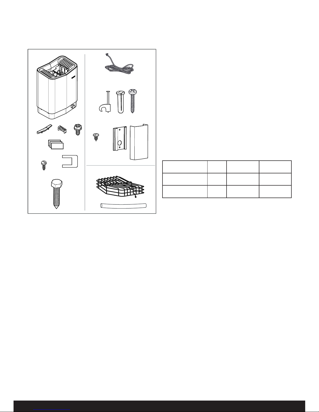
Check that the following parts are included in the packaging:
Figure 1: Sauna heater/control panel parts
1. Sauna heater
2. Herb bowl/air humidifi er
3. Brackets x 4
4. Lock screw B8x9.5 x 1
5. Warning and Caution plates for the room in multiple languages
6. Screws B 4 x 6.5 x 6 for Warning and Caution plates
7. Connectors x 3
8. Bracket screws x 4
9. NTC Sensor, cable length 4 m
10. Clips TC (3-5) x 10 pieces
11. Plastic plugs 25x5 x 2 pcs
12. Screws B6x25 x 2 pcs
13. Screw B4x6,5 x 1 piece
14. Sensor cover
15. Rock guard
16. Protection hose Ø14x150 mm x 3 pcs, for RJ10 cables (sensor, control panel, door switch)
Contact your dealer if anything is missing.
Installation tools
The following tools and materials are needed for installation and
connection:
• level
• tape measure
• electric drill
• screw drivers
Installation planning
Before starting to install your sauna heater:
• Plan the sauna heater positioning (see the Heater positioning
- normal installation section, page 4).
• Plan the control panel positioning (see the attached instructions for the control panel for allowable positioning).
• Plan the sensor positioning (see Figure 3, page 4).
• Position the air intake vent (see the Air intake vent positioning
section, page 5).
• Position the air exhaust vent (see the Air exhaust vent positioning section, page 5).
• Plan the electrical installation (see the Connection/wiring
diagram section, page 8).
2
8
6
7
15
5
1
3
4
9
10
11
12
13
14
16
Table 1: Voltage and sauna volume
Model Voltage Sauna volume
min. cu.ft.
Sauna volume
max. cu.ft.
Sense U 7 Elite/Pure
(SPU7)
208 V
240 V
175
175
265
320
Sense U 8 Elite/Pure
(SPU8)
208 V
240 V
250
250
360
440
Installation requirements
To ensure safe use of the heater, check that the following criteria
are met:
• Electrical wiring should be installed in accordance with NEC
and all state and local codes.
• Fuse size (A) and power cable size (AWG) must be suitable
for the heater (see The section called Connection/wiring
diagram, Page 8.
• The sauna ventilation must comply with the instructions in
this manual (see The section called Positioning the inlet vent,
Page 5, The section called Positioning the outlet vent, Page
5).
• The position of the sauna heater, control panel, and sensors
must comply with the instructions in this manual.
• The heater output (kW) must be suitable for the sauna
volume (cu.ft.) (See Table 1, Page 3). The minimum and
maximum volumes must not be exceeded.
• NOTE: A GFCI device is not required by ETL. A GFCI may
be installed if required by local codes. However, GFCI devices will tend to nuisance trip during use of the product.
Page 4
4
1
3
2
4
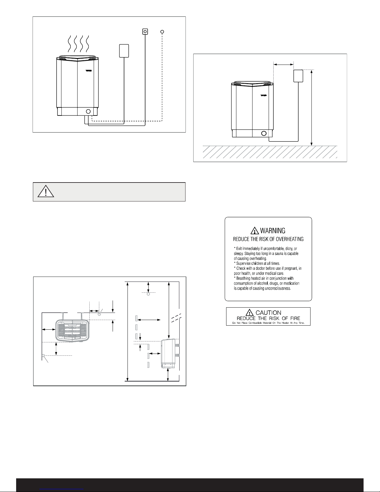
Figure 2: Schematic diagram of installation
1. Sauna heater
2. Control panel
3. Sensor
4. External on/off switch (option, door contact needed for function)
Positioning the heater - normal installation
Position the sauna heater:
• on the same wall as the door (or the side wall if very close to
the door wall).
• Position the heater at a safe distance from the fl oor, side
walls and interior fi ttings (see Figure 3).
Position the sensor according the picture (see Figure 3).
1
4
8
11
10
12
2
6
5
9
7
3
3
Figure 3: Positioning the heater - normal installation
1. Minimum distance from side wall: 4 in
2. Sensor position (option 1): 3 in from heater
3. Sensor
4. Minimum distance from back wall (with legs): 4 in
5. Sensor position (option 2): 3 in from heater front
6. Sensor position: 1 in from ceiling
7. Minimum distance from ceiling: 44 in
8. Minimum distance from interior fi ttings: 4 in
9. Minimum ceiling height: 75 in
10. Minimum distance: 1 in
11. Minimum distance from interior fi ttings: 2 in
12. Suggested distance from fl oor: 7 in
Positioning the control panel
The control panel can be installed inside or outside of the sauna
room.
The control panel must be correctly positioned with regard to
safety distances below when installed inside the sauna room
Figure 4: Safety distance, control panel
1. Heater
2. Control panel
3. Max. 36 in
4. Min. 12 in
1
2
4
3
DANGER! No more than one heater may be installed in the same sauna cabin.
Figure 5: Warning/Caution plate
Page 5
5
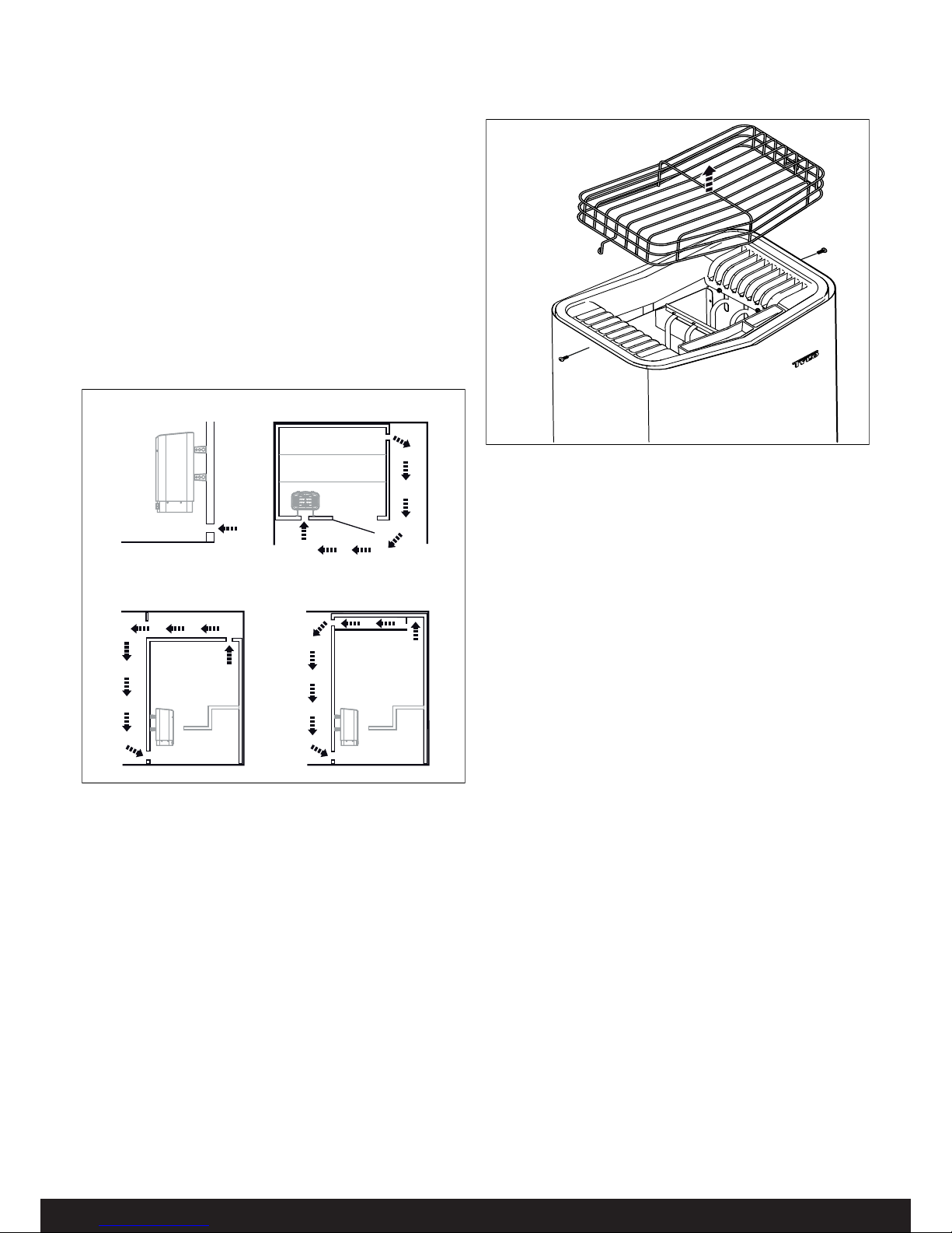
Sauna room ventilation
In a sauna, the air should be changed about 6 times an hour. See
Figure 6.
It is recommended that ventilation openings meet the requirements of UL Specifi cation 875. The minimum opening should be
determined using one of the following formulas:
For R< 31, V ≥ 9 .3
For R ≥ 31, V ≥ 0.3*R
where R = the fl oor area of the room in square feet and
V = the minimum vent size in square inches
ExampleVenting Calculation:
Room is 54 sq.ft.(9 ft. by 6 ft.) 54 is larger than 31.
Multiple 54 x 0.3 = 16.2 sq. in.
Vent size opening should be 4 in x 4 in.
Positioning the inlet vent
Install the inlet vent straight through the wall under the centerline
of the heater.
Figure 6: Positioning the air intake and exhaust vents
1. Inlet vent position.
2. Outlet vent position through the sauna wall.
3. Outlet vent position through the cavity.
4. Outlet vent position via duct.
Positioning the outlet vent
Position the outlet vent
• at the maximum possible distance from the air intake vent,
e.g. diagonally (see Figure 6).
• high on the wall or in the ceiling (see Figure 6).
• so that it vents into the space that the door and air intake
vent open into.
The outlet vent must have the same area as the inlet vent.
Ensure that the outlet vent is open.
Mechanical ventilation is not recommended due to the risk of poor
air exchange, which can negatively aff ect the heater temperature
cut-out.
Removing the Rock Guard
Unscrew the two screws on the side of the heater and lift the
rock guard upwards, see Figure 7. (This is necessary when fi lling
the stone compartment or cleaning the fragrance holder and air
humidifi er).
1 2
34
Figure 7: Removing the Rock Guard
Room construction
For safety and reliability, the following rules must be addressed.
• The enclosed WARNING: Reduce the risk of overheating
… warning plate must be mounted on or alongside the door
outside the sauna room at about eye level. Use the supplied
screws.
• The enclosed CAUTION: Reduce the risk of fi re … caution
plate must be mounted on the interior wall above the heater.
Use the supplied screws.
• No permanent locking or latch system is to be used on the
sauna door.
• Acceptable door fi ttings are: magnetic catches, friction catches, spring or gravity loaded closures. The door must always
open outwards.
• No shower may be installed in a sauna room.
• No electrical receptacle shall be installed inside the sauna
room.
• The heater should not be operated without its container properly fi lled with rocks and the rock guard in place.
• If an intercom speaker is installed, it should be away from the
heater and as close to the fl oor as possible.
• If a room light is installed, it should be a surface mounted
bracket type. Wall mounted lights should be about 70” above
the fl oor. Ceiling mounted lights should be of an approved
type with a junction box that is remote to the fi xture itself.
Use only a fi xture that uses A.F. or fi xture type internal wiring.
A 60 watt bulb should provide suffi cient lighting.
• Fire sprinkler systems installed inside any sauna room should
be properly rated for sauna room temperatures.
• Always mount the heater according to these installation
instructions.
Page 6
6
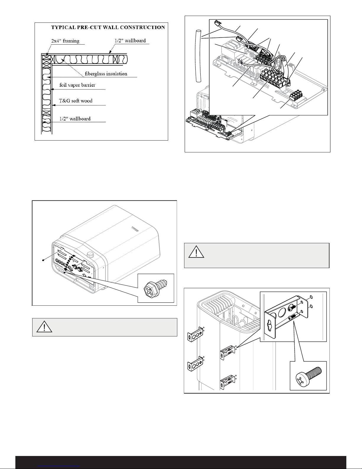
Figure 8: Typical wall construction
Connect the heater using 90°c approved rated wire for fi xed
installation. Installed shall be inaccordance with NEC and State
and local codes.
3. Connect the electrical cable (1) to the terminal (2) (see Figure
10) according to the wiring diagram (see the Connection/wiring diagram section, page 8).
4. Run the cables for the control panel and the temperature
sensor through the cable grommets (3). Connect the control
panel cable (4) to one of the four RS485 contacts (positions
5-8 Pure, 6-9 Elite) (see Figure 10) according to the wiring
diagram (see the Connection/wiring diagram section, Fig18
page 8).
5. Connect the humidity- and temperature sensors cable (6) to
one of the four RS485 contacts (positions 5-8 Pure, 6-9 Elite)
(5) according to the wiring diagram (see the Connection/wir
ing diagram section, Fig. 18 page 8).
WARNING! Always check that the heater is connected to the correct main/phase voltage!
6. Connect the light cable (if used) (7), see Figure 10, to the
terminal (8) according to the wiring diagram Figure 18.
7. Close the cover and tighten the screws (see Figure 9).
2
8
4
5
7
6
9
1
10
3
11
Figure 10: Circuit board
1. Electrical cable
2. Terminal for connection of electrical cable
3. Cable grommet (x6)
4. Control panel cable
5. Modular contacts for connection
of control panel, sensor etc.
6. Sensor cable
7. Light cable (if connected)
8. Terminal for connection of
light (if connected)
9. Strain relief connector for
cables to modular contacts
(x2)
10. Strain relief connector for
electrical cable
11. Protection hose for RJ10
cables
INSTALLATION
Sauna heater installation
It is easiest to prepare for installation with the heater lying down.
To install the heater:
1. Lay the heater down with the front facing upwards.
2. Undo the screws and open the cover (see Figure 9).
Typical wall construction
Figure 9 Opening/closing the cover
8. Unscrew the fi rst two screws on the back of the heater and
screw one of the four brackets into place. Repeat the procedure until all of the brackets are fi tted see Fig. 11.
NB: If all the screws on the back are unscrewed
simultaneously, the back plate may come loose.
For this reason, attach the four brackets to the
heater one at a time.
Figure 11: Attaching the brackets to the heater
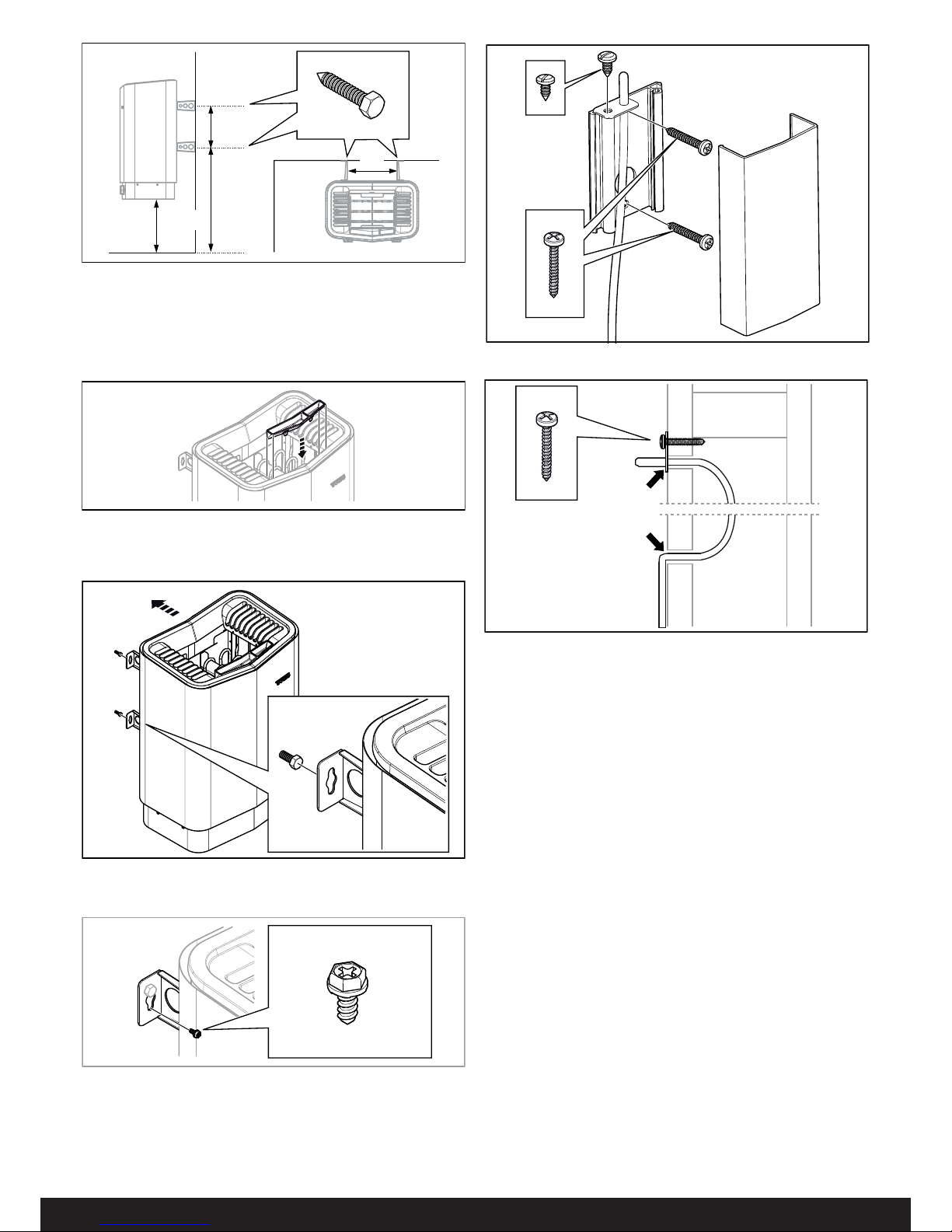
9. Position the bracket screws according to the specifi ed dimensioning see Fig. 12.
Page 7
7
Unusual voltages/numbers of phases
Contact Tylö Customer Service before connecting to voltages or
numbers of phases that are not listed in the wiring diagram Figure
18.
External ON/OFF switch (option)
The external ON/OFF switch can be positioned anywhere outside
the sauna, not to exceed 75 feet from the heater, to avoid voltage
loss in the cable. Voltage loss aff ects the LED indicator for heater
status (if built-in and connected to the switch).
For further information, see instructions supplied with the control
panel.
Figure 13: Fitting the fragrance holder/air humidifi er
11. Hang the heater on the screws see Fig. 14.
Figure 14: Hang the heater up.
12. Lock the heater into place with the lock screw see Fig. 15.
Figure 15: Lock screw for bracket
13. Install the sensor on the wall see Fig 16. The thermistor wire
may also be passed through the wall. Seal any holes in the
wall behind the sensor, see Figure 17. The thermistor wire
may be extended outside the sauna using low voltage wire
(2-lead).
Figure 12: Dimensioning
1. 10.31 in
2. 6 in
3. 16.3 in
4. 8.11 in
10. Fit herb bowl/air humidifi er (see Fig. 13).
2
4
3
1
Figure 16: Installing the sensor
Figure 17: Seal any holes
Page 8
8
Figure 18: Wiring diagram
1A. NTC Sensor
2A. Ext switch (External switch option-
al)
3A. N/A
4A. N/A
5A. N/A
6A. N/A
7A. N/A
8A. N/A
9A. Controls Elite
1B. NTC Sensor
2B. Ext switch (External switch optional)
3B. N/A
4B. N/A
5B. N/A
6B. N/A
7B. N/A
8B. Controls Pure
10. Heater
11. Terminal for connection of electrical cable
12. Control panel
(Elite - connect to positions 9A)
(Pure - connect to positions 8B)
13. Light/terminal for connection of light
14. Door contact (option)
15. External switch (option)
10
131415
12
11
13
RJ10 4P4C
3 x 14 AWG
RJ10 4P4C
RJ10 4P4C
ELITE PURE
max 75 feet
*
*
B
G
B4140
12
6789
34 5
1A 2A
6A 7A 8A 9A
3A 4A 5A
120 V~
14 AWG
Max. 6 Amp.
5,3-8,3 kW
208/240 V~
1B 2B 3B 4B
5B 6B
7B 8B
CONNECTION/WIRING DIAGRAM
TAB 208 V 1 Phase 240 V 1 Phase
Model Amperage
Amps
Output kWWire Size
AWG
Amperage
Amps
Output kWWire Size
AWG
Sense U 7 Pure/Elite 26 5,3 10 30 7,0 8
Sense U 8 Pure/Elite 30 6,3 8 35 8,3 8
Note: Heating elments do not change for voltage changes. The heater output will changed based on the voltage applied to heater.
Page 9
9
SELF-INSPECTION OF THE INSTALLATION
To check the installation:
1. Turn power on at the Circuit Breaker Box.
2. Check that the control panel lights up.
3. Start the heater (see User Guide).
4. Check that all three tubular elements start to heat up (go
red).
Please keep these instructions!.
In the event of problems, please contact the retailer where you purchased
the equipment.
© This publication many not be reproduced, in part or in whole, without
the written permission of Tylö. Tylö reserves the right to make changes to
materials, construction and design.
1234Pin:
Pos 1A.
NTC
Pin 1:
Pin 2: NTC
Pin 3: NTC
Pin 4:
Pos 2A.
Ext sw
Pin 1:
Pin 2: LED
Pin 3: SW
Pin 4: 12 V
Pos 6A-9A.
4x RS485
Pin 1: A
Pin 2: B
Pin 3: 12 V
Pin 4: GND
Pos 5B-8B.
4x RS485
Pin 1: A
Pin 2: B
Pin 3: 12 V
Pin 4: GND
Pos 3A.
Door sw
Pin 1:
Pin 2: LED
Pin 3: SW
Pin 4: 12 V
Pos 4A.
Bim/NTC
Pin 1: Bim
Pin 2: NTC
Pin 3: NTC
Pin 4: Bim
Pos 1B.
NTC
Pin 1:
Pin 2: NTC
Pin 3: NTC
Pin 4:
Pos 2B.
Ext sw
Pin 1:
Pin 2: LED
Pin 3: SW
Pin 4: 12 V
Pos 3B.
Door sw
Pin 1:
Pin 2: LED
Pin 3: SW
Pin 4: 12 V
Pos 4B.
Bim/NTC
Pin 1: Bim
Pin 2: NTC
Pin 3: NTC
Pin 4: Bim
Pos 5A.
Addon (option)
1234Pin:
10
11
1A 2A
6A 7A 8A 9A
3A 4A 5A
1B 2B 3B 4B
5B 6B
7B
8B
ELITE PURE
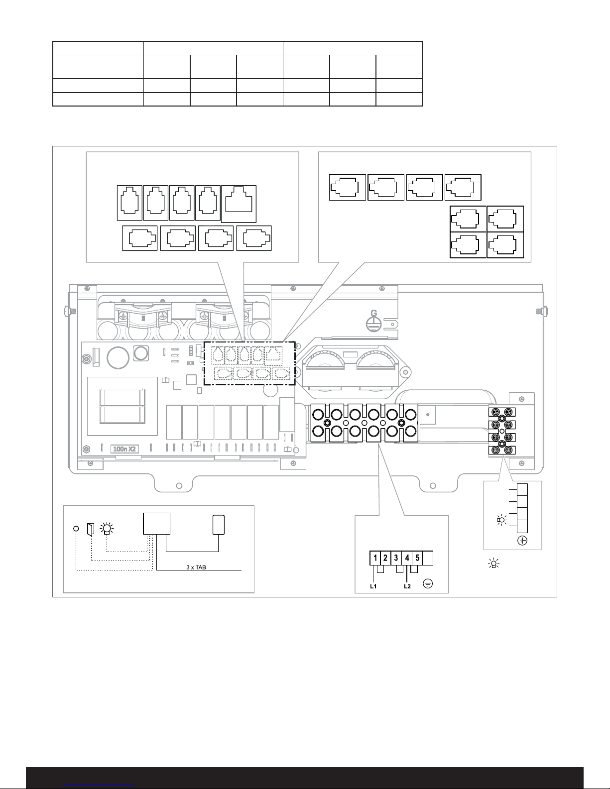
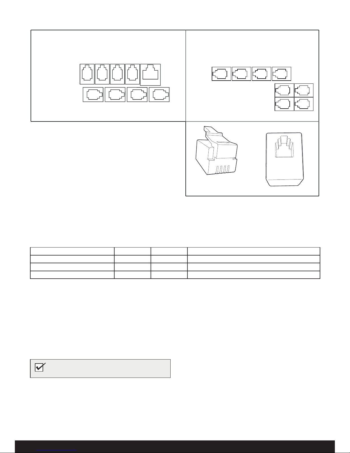
Description of cabling/modular contacts
Figure 19: Modular contacts, description
ELITE
(Pos 1-4 and 6-9: RJ10, Pos 5: RJ45)
1A. NTC Sensor
2A. Ext switch (optional)
3A. N/A
4A. N/A
5A. N/A
6A. N/A
7A. N/A
8A. N/A
9A. Controls Elite
10. Modular plug (RJ10)
11. Modular contact (RJ10)
PURE
(Pos 1-8: RJ10)
1B. NTC Sensor
2B. Ext switch (External switch
optional)
3B. N/A
4B. N/A
5B. N/A
6B. N/A
7B. N/A
8B. Controls Pure
10. Modular plug (RJ10)
11. Modular contact (RJ10)
Table 3: Connecting components in modular contacts (maximum cable area for RJ10: 0.90 mm/0.20 mm², AWG24)
Connection of Pos Pin Comment
Temp. sensor (10kohm) 1 A/B 2-3 Must be NTC model.
External switch with no wire indicator 2 A/B 3-4 Both constant or impulse deactivation works.
External switch with wire indication 2 A/B 2-3-4 12VDC (max. 40mA).
NOTE! Crimp pliers are needed if changing modular
cabling, e.g. shortening wires.
Page 10
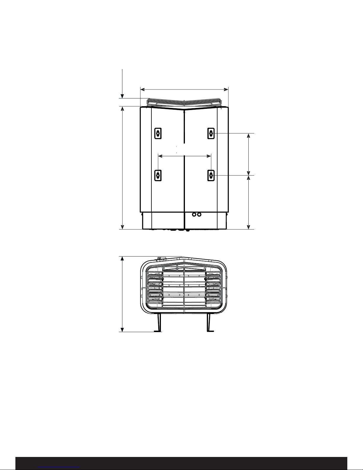
10
14,8"
1,6"
375mm
17,0"
23,6"
431mm
600mm 41mm
206mm
8,11"
262mm
262mm
10,31"
262mm
10,31"
DIMENSIONS
Page 11

11
USER GUIDE
GENERAL INFORMATION
Congratulations on your new sauna heater! Follow this user guide
to get the most from your purchase.
Wet and dry saunas are forms of bathing which originate way
back in history. A hot sauna is best enjoyed at temperatures between 145-190°F.
PRIOR TO USE
The fi rst time you use the heater
Fill the stone compartment
Fill the stone compartment around the heating elements from the
bottom to the top, to approx. 2” above the top front edge. Do not
press the stones into place. Capacity: Approx. 35 lb of stones.
Place the stones loosely to allow optimum air circulation. The tubular heating elements must not be squeezed together or against
the side.
Sauna stones must:
• tolerate extreme heat and fl uctuations caused by water being
poured on them.
• be cleaned before use.
• must have an uneven surface, so that the water "clings" to
the stone surface and evaporates effi ciently.
• be between 1-1/2” to 2” in size to allow air circulation in the
stone compartment. This will increase the life of the tubular
elements.
Default settings
Using the control panel for the fi rst time:
See instructions supplied with the control panel.
Prior to each use
Check the following
Check that:
• there are no foreign objects in the sauna cabin, on or in the
heater.
• the door and any windows to the sauna cabin are closed.
• that the sauna door opens outwards with a little pressure.
NB:
DANGER! Fragrant essences and similar products may ignite, if poured directly onto the
stones.
Figure 2: Positioning of the main power switch
1. Main power switch
Figure 1: Filling the stone compartment
1. Stone compartment
2. Side chambers
Turn on the heater to remove any new paint odors
To remove "new paint odor" from the heater:
Heat the sauna heater for about one hour. The water reservoir
does not need to be working.
A little smoke may appear.
NB: Always use dolerite stones (Tylö Sauna Stones)!
"Ordinary" stones may damage the heater.
Do not use ceramic stones. Ceramic stones may
damage the heater. The heater guarantee does not
cover damage caused by ceramic stones.
NB: Never place stones on top of the side air
chambers. This way will obstruct air circulation,
causing the unit to overheat and the cut-out switch
to activate.
1
2
NOTE! Do not use the sauna cabin for any purpose
other than taking saunas.
Turn on the main power switch
The main power switch is at the bottom of the heater.
Switch it on, if it is not already switched on (see Figure 2).
1
Page 12

12
USE
The control panel in general
See instructions supplied with the control panel.
EXTERNAL ON/OFF SWITCH (OPTION)
External ON/OFF switch can be installed anywhere outside the
sauna. The switch is momentary pulse or constant activation.
The heater circuit automatically recognises which is used. Heater
status and faults on the door contact can be seen if the switch has
a built-in LED.
See instructions supplied with the control panel.
Figure 3: Other functions
1. Fragrance holder
2. Air humidifi er
To create a pleasant fragrance in the sauna, pour a few drops of
Tylö Sauna Fragrance into the water in the fragrance holder.
You can also mix a few drops of the sauna fragrance with water in
a sauna bucket and pour the water on fully heated stones. Use a
sauna ladle for pouring water on the hot stones.
Tylö Sauna Fragrance comes in diff erent variants and fragrances.
Go to www.tylo.com to see the full range.
To maintain a comfortable basic level of humidity in the sauna, fi ll
the built-in air humidifi er (see Fig. 3) with water before switching
on the sauna.
Fragrance holder
Figure 5: Cleaning the fragrance holder and air humidifi er
Check the stone compartment
Check the stone compartment at least once annually or as many
times per year as the heater is used per week.
Example: If the unit is used 3 times a week, check the stone
compartment 3 times per year.
How to check the stone compartment:
1. Remove all stones from the compartment.
2. Remove any small stones, gravel and limescale from the
compartment.
3. Put whole, undamaged stones back. Replace damaged stones with new ones as required (see Filling the stone compartment, page 5).
Air humidifi er
DANGER! Fragrant essences etc. may ignite if
poured directly onto the stones.
1
2
DANGER! Do not pour water into the fragrance
holder once it has been heated up, as this can cause
boiling water to splash on the sauna occupants. Do
not stand or sit in front of the heater while water is
being poured into the fragrance holder, as hot water
can spray out suddenly.
Tip: Pour a few drops of diluted sauna fragrance into
the built-in air humidifi er.
MAINTENANCE
Cleaning the fragrance holder and air humidifi er
Clean the fragrance holder and air humidifi er as required.
To clean the fragrance holder and air humidifi er:
Remove the fragrance holder/air humidifi er and rinse them under
running water.
AFTER USE
Switch off the main power switch.
The main power switch is at the bottom of the heater.
Switch off here when the heater is not to be used for an extended
period (e.g. several weeks).
WARNING! If the stone compartment fi lls up with
gravel and small stones, the tubular element can be
damaged as a result of overheating, as air fl ow will
be insuffi cient.
1
Figure 4: Positioning of the main power switch
Page 13

13
Figure 6: Resetting the temperature cut-out
1. Temperature cut-out sauna heater
1
Troubleshooting the control panel
See instructions supplied with the control panel.
TROUBLESHOOTING
Temperature Safety Switches
The heater's temperature protection devices:
• PCA - The temperature safety on the PCA in the heater is designed to prevent components being damaged by overheating. If
the safety switch is triggered, an error code shows on the control
panel display.
If the overheating switch has activated, the heater cannot be
started again until the temperature has dropped down 68 degrees
(ºF) on the PCA.
• Heater - The temperature cut-out in the heater protects the components and woodwork in the sauna from overheating. There
is a white reset button on the left side of the heater which must be
pressed in (see Fig. 9). If the heater safety switch has activated,
the button will feel stiff and will ‘click’ when reset.
Information!
When the overheating safety switches activate, always check the
cause of the problem. The life of the elements and PCA can be
adversely eff ected by each overheating. If systems continues to
overheat look at the following: Ventilation defi cient? Room volume? Internal heater fault?
Page 14

14
Symptom Possible cause Remedy
Heater element
in heater stone
compartment does
not warm up.
1. Temperature settings on control panel do not correspond to operating status?
2. Water reservoir in operation? Only two of the
three heater elements in the stone compartment can operate at the same time as the tank,
otherwise excessive current is drawn from the
electricity supply. This is not a fault outside normal operation.
3. Some of the heater fuses on the main switchboard can have tripped out?
4. Resistor coil in the heater element faulty?
5. Internal heater PCB fault?
1. Set temperature to correspond to heater element
operation in stone compartment.
2. See the instructions supplied with the control
panel.
3. Check and replace/reset the fuses in the main
switchboard.
4. An authorised electrician is required to fi nd the
fault.
5. An authorised electrician is required to fi nd the
fault.
Lights in the sauna
do not come on
when switched on
at the control panel.
1. Is lighting connected via the heater?
2. Internal heater PCB fault?
1. Verify with authorized electrician who performed
installation of heater/lighting.
2. An authorized electrician is required to fi nd the
fault.
Heater does not
work, control panel
does not light up.
1. The main power switch is off ?
2. Circuit breaker tripped on main electical panel.
3. Loose contact in cabling between heater and
control panel?
4. The specifi c 12VDC output on one of the PCB's
RS485 modular jack to the control panel is faulty
due to short-circuit?
5. Transformer on PCB in heater faulty?
6. Control panel faulty?
1. Turn heater main power switch.
2. Check and replace/reset the fuses in the main
switchboard.
3. Switch off heater main power switch and connect
each/paired cable to the control panel. Switch on
heater main power switch again. If this does not
help, an authorized electrician is required to fi nd
the fault.
4. Requires an authorized electrician to fi nd the fault,
faulty 12VDC output is indicated by LED out next
to the RS485 output. Note: if the fault is in the
RJ10 cable to the control panel, do not click into
a working vacant RS485 outlet to avoid causing a
fault in that outlet. RJ10 cable must be replaced/
contacts fi tted in the event of a fault.
5. An authorized electrician is required to fi nd the
fault.
6. An authorized electrician is required to fi nd the
fault.
The fuses or circuit
breaker in the building breaker panel
trips as soon as the
heater is turned on.
1. There is a short-circuit at the heater GND. Can
be due to a faulty heater element?
2. Lighting connected to and controlled via the
heater faulty?
3. The heater has not been used for a long period,
causing an insulation fault in the heater element?
4. Heater has had too much water poured on it?
5. Other internal heater fault?
1,2,3,4,5. Do not use the heater, switch off at main
heater main switchboard trip and disconnect heater fuses on the main switchboard. An authorized
electrician is required to fi nd the fault.
Troubleshooting the sauna heater
Information!
Contact the dealer during the guarantee period in the event of faults.
See the instructions for the control panel for details of faults not covered in this user guide.
Table 1: Troubleshooting the sauna heater
Page 15

15
Please keep these instructions!.
In the event of problems, please contact the retailer where you purchased
the equipment.
© This publication many not be reproduced, in part or in whole, without
the written permission of Tylö. Tylö reserves the right to make changes to
materials, construction and design.
Figure 8: Symbol
The diff erent materials can be recycled as specifi ed by their
labelling.
You can help protect the environment by recycling or reusing the
spent appliances or the materials in them. Take the product to a
recycling centre without the sauna stones or the soapstone jacket
(if fi tted).
Contact your local authorities for details of your nearest recycling
centre.
ROHS (RESTRICTION OF HAZARDOUS SUBSTANCES)
Instructions for environmental protection:
Do not dispose of this product with the domestic refuse when no
longer in use. Take it to a recycling station for electrical and electronic equipment instead.
For further information, see the symbol on the product, manual or
packaging.
SPARE PARTS LIST
Figure 7: Spare parts 1
1. U8 Pure/Elite Tubular Elements 3001-924
U7 Pure/Elite Tubular element 3001-920
2. Stone compartment n/a
3. Circuit board Elite 9600 0068
Circuit board Pure 9600 0067
4. Terminal block 9600 0723
5. Sauna heater temperature safety switch 3119-607
6. Strain relief connector 9600 0554
7. On/Off Switch 9600 0040
8. On/off dial 9600 0132
9. Rock Guard 8019-541
10. NTC Sensor 9600 0219
3
7
8
9
10
4
6
5
2
1
Page 16

16
GND
MH
X1 X2 X3
X4 X5X6X7
X8 X9 X10 X11 X12 X13 X14 X15 X16
X17 X18
H3H2H1
H.Tank
Light
Aux 0
Sec/NTC
12345G
BB4140
fed
cba
654
321
L1 L2
GND
208-240V, 1-ph
FRONT
MIDDLE
BACK
GND GND
Switch
Circuit board
Type
kW
Amp Amp
208 V~ 240 V~
AWG AWG
Sense
Plus-U 7
Sense
Plus-U 8
5.3
6.3
7.0
8.3
26
30
-
-
10
8
-
-
-
-
30
35
-
-
8
8
Use only 194° F copper wire
Don´t forget to earth (ground)!
120 V~ N
13
42
High Limit Control
Heater
AWG 14
Max 6 Amp.
120 Volt Light input
(Separate from
Heater Power)
Output to light
HEATER WIRING DIAGRAM
Page 17

17
NOTICE D'INSTALLATION........................................................ 18
AVANT L'INSTALLATION .................................................................... 18
Pièces ..................................................................................... 18
Exigences relatives à l'installation .......................................... 18
Outils d'installation .................................................................. 18
Planifi er l'installation ............................................................... 18
INSTALLATION .................................................................................... 21
Installation du poêle de sauna ................................................ 21
Interrupteur extérieur M/A (option) .......................................... 22
BRANCHEMENT/CÂBLAGE ....................................................... 23
Description des câblages/prises modulaires ................. 24
AUTOCONTRÔLE DE L'INSTALLATION................... 24
DIMENSIONS.......................................................................... 25
NOTICE D'UTILISATION............................................................ 26
INFORMATIONS GÉNÉRALES .......................................................... 26
AVANT L'UTILISATION ....................................................................... 26
Avant la première utilisation du poêle ..................................... 26
Avant chaque utilisation .......................................................... 26
UTILISATION ........................................................................................ 27
Généralités relatives au panneau de commande.................... 27
Autres fonctions....................................................................... 27
INTERRUPTEUR EXTÉRIEUR M/A (OPTION) ............................ 27
APRÈS L'UTILISATION ....................................................................... 27
Mettre l'appareil hors tension au moyen de l'interrupteur
principal................................................................... ................ 27
ENTRETIEN .......................................................................................... 27
Nettoyage du récipient à parfum et de l'humidifi cateur
................. 27
Contrôler le réservoir à pierres ............................................... 27
DÉPANNAGE ........................................................................................ 28
Dépannage du panneau de commande ................................. 28
Dépannage du poêle............................................................... 29
LISTE DES PIÈCES DE RECHANGE ................................................ 30
ROHS (RESTRICTION OF HAZARD US SUBSTANCES)
........................ 30
SCHÉMA DE CÂBLAGE DU POÊLE
....................................................... 31
AVERTISSEMENT !
• Risque de choc électrique - matériel à haute tension. Ce matériel ne contient aucune pièce réparable par l'utilisateur. Toute
installation et service de ce matériel doivent être eff ectués par
un personnel certifi é et qualifi é conformément aux codes locaux
et nationaux.
• Ne pas construire la cabine de sauna de manière à limiter la
circulation d'air à travers le fond du poêle.
• Empilez les pierres sans trop les serrer, au risque de déclencher la protection thermique.
• Maintenez un dégagement minimum entre le poêle et les surfaces en bois (bancs, cloisons latérales, grille de protection, etc.).
Les supports de montage sont fournis. Ils assurent un dégagement adéquat par rapport au mur derrière le poêle.
• Utilisez uniquement du fi l de cuivre de la taille et du type indiqués dans le tableau des caractéristiques du poêle et dont la
température admissible est indiquée sur le boîtier de raccordement du poêle.
• Une rambarde ou un manteau de protection extérieur sont
nécessaires autour du poêle pour éviter les brûlures de contact
accidentel.
• Tous les poêles et les commandes doivent être mis à la terre
conformément au code NEC pour éviter tout choc électrique en
cas de panne de l'appareil.
• Ne pas monter de prises ou de boîtiers électriques à l'intérieur
d'une cabine de sauna.
• Ne pas placer de banquettes au-dessus du poêle.
• Pour usage domestique uniquement.
Conservez la présente notice d'utilisation !
En cas de problèmes, veuillez contacter le revendeur
où vous avez acheté le matériel.
© Cette publication ne peut être reproduite, en tout ou en partie, sans la
permission écrite de Tylö. Tylö se réserve le droit d'apporter des modifi cations dans les matériaux, dans la construction et dans la conception.
* L'hyperthermie survient lorsque la température interne du
corps atteint un niveau de plusieurs degrés au-dessus de la
température normale de 37° C (98,6° F). Les symptômes de
l'hypothermie comprennent une augmentation de la température interne du corps, des étourdissements, la léthargie, la
somnolence et l'évanouissement. Les eff ets de l'hyperthermie
comprennent :
a) L’omission de percevoir la chaleur ;
b) Ne pas reconnaître la nécessité de sortir de la cabine ;
c) L’ignorance des dangers imminents ;
d) Des dommages fatals pour les femmes enceintes ;
e) L'incapacité physique de sortir de la cabine et
f) La perte de conscience
• La consommation d'alcool, de drogues ou de médicaments
est fortement déconseillée avant d'entrer dans une cabine de
sauna.
• Les femmes enceintes ou les personnes ayant une mauvaise
santé devront consulter leur médecin avant d'utiliser un sauna.
• Attention risques d'incendie : Ne pas utiliser la cabine de sauna
pour faire sécher des vêtements, des maillots de bain, etc. Ne
pas accrocher les serviettes au-dessus du poêle ou placer un
objet autre que les pierres fournies sur le poêle. Si un noircissement de la paroi autour du poêle apparaît, cessez immédiatement l'utilisation de sauna.
• Examinez le sauna régulièrement pour l'entretien requis du
poêle, des commandes et des banquettes. Remplacer les surfaces en bois qui présentent des signes de détérioration.
• Le poêle devient extrêmement chaud pendant le fonctionnement. Risques de brûlures en cas de contact avec les surfaces.
• Les enfants mineurs doivent être surveillés de manière adéquate lorsqu'ils sont à proximité d'un sauna chaud ou en phase de
réchauff ement.
• Les systèmes de sécurité anti-incendie (sprinkler) utilisés à l'intérieur d'une cabine de sauna doivent être correctement réglés
en fonction des températures de la cabine.
• Ne pas verser de l’eau chlorée de piscine ou de spa sur le
poêle. L'utilisation excessive d'eau sur le poêle peut provoquer
des dommages et annuler la garantie.
• Cet équipement ne doit pas être utilisé par des personnes (y
compris des enfants) aux capacités physiques, sensorielles
ou mentales aff aiblies, ou n’ayant pas assez d’expérience et
de connaissance, à moins d’être surveillées ou d’avoir reçu
des instructions concernant l’utilisation de l’équipement, de la
part d’une personne responsable de leur sécurité. Les enfants
doivent être surveillés afi n de s’assurer qu’ils ne jouent pas
avec l’appareil.
Page 18

18
NOTICE D'INSTALLATION
AVANT L'INSTALLATION
Pièces
Vérifi ez que tous les éléments suivants se trouvent bien dans
l'emballage :
Outils d'installation
Les outils et les matériaux suivants sont nécessaires pour l'installation et le branchement :
• niveau
• mètre-ruban
• perceuse électrique
• tournevis
Planifi er l'installation
Avant de commencer à installer votre poêle de sauna :
• Planifi er l'emplacement du poêle (voir Emplacement du poêle
: paragraphe Montage normal, page 19).
• Planifi er l'emplacement du panneau de commande (voir les
instructions ci-jointes pour le panneau de commande pour
l'emplacement adéquat).
• Planifi er l'emplacement de la sonde (voir Fig. 3, page 19).
• Positionner la bouche d'entrée d'air (voir le paragraphe
Emplacement de l'entrée d'air, page 20).
• Positionner la sortie d'air (voir le paragraphe Emplacement
de la sortie d'air, page 20).
• Planifi er l'installation électrique (voir le paragraphe Schéma
de raccordement/branchement, page 23).
2
8
6
7
15
5
1
3
4
9
10
11
12
13
14
16
Tableau 1 : Tension et volume du sauna
Modèle Tension Volume du
sauna min.
pi³
Volume du
sauna max.
pi³
Sense U 7 Pure/Elite
(SPU7)
208 V
240 V
175
175
265
320
Sense U 8 Pure/Elite
(SPU8)
208 V
240 V
250
250
360
440
Exigences relatives à l'installation
Pour garantir une utilisation sûre du poêle, vérifi ez que les
critères suivants sont respectés :
• Le câblage électrique doit être installé conformément au
code national d'électricité américain (NEC) et à tous les codes nationaux et locaux du pays où le système est installé.
• La taille du fusible (A) et la taille du câble d'alimentation
(AWG) doivent être adaptées au poêle (voir le paragraphe
intitulé Schéma de raccordement/branchement, Page 23.
• La ventilation du sauna doit se conformer aux instructions
de ce manuel (voir le paragraphe intitulé Emplacement de
l'entrée d'air, Page 20, le paragraphe intitulé Emplacement
de la sortie d'air, Page 20).
• L'emplacement du poêle, du panneau de commande et des
sondes doit se conformer aux instructions de ce manuel.
• La puissance du poêle (kW) doit être adaptée au volume du
sauna en m3 (pi³) (Voir tableau 1, page 18). Les volumes
minimum et maximum ne doivent pas être dépassés.
• REMARQUE : Un dispositif DDFT n’est pas requis par ETL.
Un DDFT peut être installé si requis par les codes locaux.
Cependant, les dispositifs DDFT ont tendance à se déclencher de manière intempestive lors de l'utilisation du produit.
Fig. 1 : Éléments du poêle de sauna/panneau de commande
1. Poêle de sauna
2. Coupelle à herbes aromatiques/humidifi cateur
3. Supports x 4
4. Vis de fi xation B8x9,5 x 1 pièce
5. Plaques d’avertissement et de danger pour la cabine en
plusieurs langues
6. Vis B 4 x 6,5 x 6 pour plaques d’avertissement et de danger
7. Connecteurs x 3
8. Vis pour supports x 4
9. Capteur CTN, longueur de câble 4 m
10. Clips TC (3-5) x 10 pièces
11. Bouchon plastique 25 x 5 x 2 pièces
12. Vis B6x25 x 2 pièces
13. Vis B4x6,5 x 1 pièce
14. Capot de capteur
15. Protège-pierres
16. Gaine de protection Ø14x150 mm x 3 unites, pour les câbles
RJ10 (sonde, panneau de commande, contacteur de porte)
Contactez votre revendeur s'il manque une pièce quelconque.
Page 19

19
1
3
2
4
Fig. 2 : Schéma électrique de l'installation
1. Poêle de sauna
2. Panneau de commande
3. Sonde
4. Interrupteur extérieur marche/arrêt (option, contacteur de
porte nécessaire pour la fonction)
Emplacement du poêle - montage normal
Placez le poêle de sauna :
• sur le même mur que la porte (ou la cloison latérale s'il est
très près du passage de porte).
• Placez le poêle à une distance appropriée du sol, des cloisons latérales et des aménagements (voir Fig. 3).
Placez la sonde comme illustré (voir Fig. 3).
1
4
8
11
10
12
2
6
5
9
7
3
3
Fig. 3 : Emplacement du poêle - montage normal
1. Distance minimale par rapport aux cloisons latérales : 100
mm (4 po)
2. Emplacement de la sonde option 1 : 70 mm (3 po) du poêle
3. Sonde
4. Distance minimum à la paroi de fond (pieds inclus) : 95 mm
5. Emplacement de la sonde option 2 : 70 mm (3 po) de l'avant
du poêle
6. Emplacement de la sonde : 25 mm (1 po) du plafond
7. Distance minimale par rapport au plafond : 1 100 mm (44 po)
8. Distance minimale par rapport aux aménagements : 100 mm
(4 po)
9. Hauteur minimale sous plafond : 1 900 mm (75 po)
10. Distance minimale : 25 mm (1 po)
11. Distance minimale par rapport aux aménagements : 50 mm
(2 po)
12. Distance par rapport au sol : 18 mm (7 po)
Emplacement du panneau de commande
Le panneau de commande peut être monté à l'intérieur ou à l'extérieur de la cabine de sauna.
Le panneau de commande doit être correctement positionné en
ce qui concerne les distances de sécurité ci-dessous, lorsqu'il est
installé dans le sauna
Fig. 4 : Distance de sécurité, panneau de commande
1. Poêle
2. Panneau de commande
3. 910 mm (36 po) max.
4. 300 mm (12 po) min.
1
2
4
3
DANGER ! L'installation de plus d'un poêle dans
une même cabine de sauna est à proscrire.
Fig. 5: Avertissement/Attention plaques
AVERTISSEMENT
ATTENTION
RÉDUISEZ LE RISQUE DE SURCHAUFFE
RÉDUISEZ LE RISQUE D’INCENDIE
* Sortez immédiatement en cas de malaise, de vertige
ou de somnolence. Un séjour prolongé dans un
sauna peut provoquer une hyperthermie.
* Les enfants doivent être sous surveillance constante.
* Si vous êtes enceinte, malade ou sous soins
médicaux, demandez l’avis d’un médecin avant
d’utiliser le sauna.
*
L’inhalation de l’air chauff é combinée à la consommation
d’alcool, de drogues ou de médicaments peut provoquer
une perte de connaissance.
Ne posez jamais de matériau combustible sur le poêle.
Page 20

20
Ventilation de la cabine du sauna
Dans un sauna, l'air doit être renouvelé environ 6 fois par heure.
Voir la Fig. 6.
Il est recommandé que les ouvertures de ventilation soient conformes aux exigences de la norme UL 875. L'ouverture minimale
devra être déterminée en utilisant l'une des formules suivantes :
Pour R< 31, V ≥ 9 ,3
Pour R ≥ 31, V ≥ 0,3*R
où R = la surface de plancher de la cabine en m2 (pi2) et
V = la taille de la bouche d'air minimum en mm2 (pouces
carrés)
Emplacement de l'entrée d'air
Installer l'entrée d'air directement à travers la cloison, sous l'axe
central du poêle.
Fig. 6 : Emplacement des bouches d'entrée et de sortie d'air
1. Emplacement de l'entrée d'air.
2. Emplacement de la sortie d'air à travers la paroi du sauna.
3. Emplacement de la sortie d'air à travers la cavité.
4. Emplacement de la sortie d'air par le biais de la conduite.
Emplacement de la sortie d'air
Monter la sortie d'air
• à une distance maximale par rapport à l'entrée d'air, par
exemple en diagonale (voir Fig. 6).
• en hauteur sur la cloison, ou au plafond (voir Fig. 6).
• de sorte que l'air débouche dans l'espace sur lequel donnent
la porte et l'entrée d'air.
Les bouches de sortie et d'entrée d'air doivent avoir la même
section.
Veiller à ce que la sortie d'air soit ouverte.
L'installation d'une ventilation mécanique est déconseillée, un
mauvais échange d'air pouvant aff ecter la protection thermique de
l'appareil.
Retrait du protège-pierres
Desserrer les deux vis sur le côté du poêle et soulever le
protège-pierres vers le haut, voir Fig. 7. (Ceci est nécessaire lors
du remplissage du compartiment de pierres ou du nettoyage du
récipient à parfum et de l'humidifi cateur).
1 2
34
Fig. 7 : Retrait du protège-pierres
Conception de la cloison
Les règles suivantes doivent être observées, pour des raisons de
sécurité et de fi abilité.
• L'AVERTISSEMENT ci-joint : Réduire le risque de surchauff e
... la plaque d'avertissement doit être montée sur ou à côté
de la porte, à l'extérieur du sauna, au niveau des yeux. Utilisez les vis fournies.
• Le texte de PRUDENCE ci-joint : Réduire le risque d’incendie... la plaque de PRUDENCE doit être montée sur la paroi
intérieure, au-dessus du poêle. Utilisez les vis fournies.
• Aucun système de fermeture permanent ne doit être utilisé
sur la porte du sauna.
• Les ferrures de portes acceptables sont : loquets magnétiques, loquets à friction, fermetures à ressort ou par gravité.
La porte doit toujours ouvrir vers l'extérieur.
• Aucune douche peut être installée dans une cabine de sauna.
• Ne pas monter de boîtier électrique à l'intérieur de la cabine
de sauna.
• Le poêle ne doit pas être utilisé sans son récipient correctement rempli de pierres et le protège-pierres en place.
• Si un haut-parleur d'interphone est installé, il devra être éloigné du poêle et placé le plus près du sol possible.
• Si un éclairage ambiant est installé, il devra être du type
monté en surface. Les éclairages muraux devront se placer
à environ 1 750 mm (70") au-dessus du sol. Les luminaires
de plafond devront être d'un type approuvé avec un boîtier de
raccordement qui est à distance du luminaire lui-même. Utilisez uniquement un appareil qui utilise A.F. ou un appareil de
type à câblage interne. Une lampe de 60 W devrait fournir
un éclairage suffi sant.
• Les systèmes de sécurité anti-incendie (sprinkler) installés à
l'intérieur d'une cabine de sauna doivent être correctement
réglés en fonction des températures de la cabine.
• Toujours monter le poêle selon les présentes instructions
d'installation.
Page 21

21
Fig. 8 : Construction murale typique
Utiliser un câble standard (norme FK ou EKK) homologué pour
installation fi xe pour raccorder le poêle.
Le cas échéant, les fi ls électriques simples (FK) seront protégés
du poêle par des gaines (PV).
3. Raccorder le câble électrique (1) au bornier (2) (voir Fig. 10),
en suivant le schéma de raccordement (voir le paragraphe
Schéma de raccordement/branchement, page 23).
4. Acheminer les câbles du panneau de commande et de la
sonde de température à travers les passe-câbles (3). Raccorder le câble du panneau de commande (4) à l’un des quatre
connecteurs RS485 (pos. 5-8 Pure, 6-9 Elite) (voir Fig. 10),
en suivant le schéma de raccordement (voir le paragraphe
Schéma de raccordement/branchement, Fig 18 page 23).
5. Raccorder le câble des sondes d’humidité et de température
(6) à l’un des quatre connecteurs RS485 (pos. 5-8 Pure, 6-9
Elite) (5), en suivant le schéma de raccordement (voir le paragraphe Branchement/Schéma de câblage, Fig.18 page 23).
AVERTISSEMENT ! Toujours vérifi er que le poêle
est raccorder à la bonne tension principale/tension de phase !
6. Raccorder le cas échéant le câble de l’éclairage (7) voir Fig.
10, au bornier (8) en suivant le schéma de raccordement
Fig.18.
7. Fermer le volet et serrer les vis (voir Fig. 9).
2
8
4
5
7
6
9
1
10
3
11
Fig. 10 : Carte électronique
1. Câble électrique
2. Bornier pour le raccordement du
câble électrique
3. Passe-câble (x6)
4. Câble du panneau de commande
5. Prises modulaires pour le
raccordement du panneau de
commande, de la sonde, etc.
6. Câble de sonde
7. Câble d’éclairage (le cas
échéant)
8. Bornier pour le raccordement de l'éclairage (le cas
échéant)
9. Connecteur anti-arrachement pour câbles des prises
modulaires (x2)
10. Connecteur anti-arrachement pour câble électrique
11. Gaine de protection pour
les câbles RJ10
INSTALLATION
Installation du poêle de sauna
Il est plus facile de se préparer pour l’installation avec le poêle en
position couchée.
Pour installer le poêle :
1. Poser le poêle au sol, face antérieure vers le haut.
2. Desserrer les vis et ouvrir le volet (voir la fi gure 9).
Construction murale typique
CONSTRUCTION MURALE PRÉDÉCOUPÉE TYPIQUE
panneau mural 1/2"
cadre 2x4"
isolation en fi bre de verre
barrière vapeur en fi lm d'aluminium
bois tendre à languette et rainure
panneau mural 1/2"
Fig. 9 : Ouverture/fermeture du volet
8. Déposer les deux premières vis de la face arrière du poêle et
visser l'un des quatre supports. Répéter l'opération jusqu'à ce
que tous les supports soient en place, voir la fi gure 11.
NOTE : Si toutes les vis de la face arrière sont
déposées en même temps, la tôle risque de se
détacher. Par conséquent, monter les quatre supports sur le poêle l'un après l'autre.
Fig. 11: Monter les supports sur le poêle
9.
Installer les vis pour support d'après les cotes, voir la fi gure 12.
Page 22

22
Tensions/nombre de phases inhabituelles
Pour un raccordement à d'autres tensions ou d'autres nombres
de phases ne fi gurant pas sur le schéma Fig. 18, contacter le
service de maintenance Tylö.
Interrupteur extérieur M/A (option)
L'interrupteur extérieur M/A peut être positionné n'importe où à
l'extérieur du sauna, sans dépasser 23 m (75 pi) depuis le poêle,
pour éviter la perte de tension dans le câble. La perte de tension
aff ecte l'indicateur LED de l'état du poêle (si intégré et raccordé à
l'interrupteur).
Pour plus d'informations, voir les instructions fournies avec le
panneau de commande.
Fig. 13 : Montage du récipient à parfum/de l'humidifi cateur
11. Accrocher le poêle aux vis, voir la fi gure 14.
Fig. 14 : Fixer le poêle
12. Immobiliser le poêle au moyen de la vis de fi xation, voir la
fi gure 15.
Fig. 12 : Cotes
1. 262 mm (10.31 po)
2. 270 mm (6 po)
3. 532 mm (16.3 po)
4. 206 mm (8.11 po)
10. Coupelle à herbes/humidifi cateur (voir la fi gure 13).
2
4
3
1
Fig. 15 : Vis de fi xation du support
13. Installer le capteur sur la cloison, voir la fi gure 16. Le câble
du thermistor peut également passer à travers la cloison.
Boucher, le cas échéant, les orifi ces dans la cloison derrière
le capteur, voir la fi gure 17,. Il est possible de prolonger le
câble du thermistor en utilisant un câble (2 conducteurs)
basse tension, à l'extérieur du sauna.
Fig. 16 : Montage du capteur
Fig. 17 : Boucher les orifi ces, le cas échéant
Page 23

23
Fig. 18 : Schéma de branchement
1A. Sonde NTC
2A. Inter. ext. (Interrupteur extérieur
option)
3A. N/A
4A. N/A
5A. N/A
6A. N/A
7A. N/A
8A. N/A
9A. Panneaux de commande Elite
1B. Sonde NTC
2B. Inter. ext. (Interrupteur extérieur
option)
3B. N/A
4B. N/A
5B. N/A
6B. N/A
7B. N/A
8B. Panneaux de commande Pure
10. Poêle
11. Bornier pour le raccordement du câble
électrique
12. Panneau de commande
(Elite - raccorder aux positions 9A)
(Pure - raccorder aux positions 8B)
13. Éclairage/bornier pour le raccordement de
l'éclairage
14. Contacteur de porte (option)
15. Interrupteur extérieur (option)
10
131415
12
11
13
RJ10 4P4C
3 x 14 AWG
RJ10 4P4C
RJ10 4P4C
ELITE PURE
max 75 feet
*
*
B
G
B4140
12
6789
34 5
1A 2A
6A 7A 8A 9A
3A 4A 5A
120 V~
14 AWG
Max. 6 Amp.
5,3-8,3 kW
208/240 V~
1B 2B 3B 4B
5B 6B
7B 8B
SCHÉMA DE RACCORDEMENT/BRANCHEMENT
TAB 208 V monophasé 240 V monophasé
Modèle Intensité A Puissance kWSection du con-
ducteur AWG
Intensité A Puissance kWSection du con-
ducteur AWG
Sense U 7 Pure/Elite 26 5,3 10 30 7,0 8
Sense U 8 Pure/Elite 30 6,3 8 35 8,3 8
Page 24

24
AUTOCONTRÔLE DE L'INSTALLATION
Pour contrôler l'installation :
1. Brancher l'alimentation principale du poêle.
2. S'assurer que le panneau de commande est allumé.
3. Mettre le poêle en marche (voir Notice d'utilisation).
4. Vérifi er que les trois résistances s'allument (deviennent
rouges).
Conserver la présente notice d'utilisation !
En cas de problèmes éventuels, veuillez vous adresser au point de vente.
© Toute reproduction, intégrale ou partielle, est interdite sans l'autorisation
écrite de Tylö. Tylö se réserve le droit de procéder sans préavis à des
modifi cations des matériaux, de la conception et du design.
Description des câblages/prises modulaires
Fig. 19 : Prises modulaires, description
ELITE
(Pos. 1-4 et 6-9 : RJ10, Pos. 5 : RJ45)
1A. Sonde NTC
2A. Inter. ext. (Interrupteur extérieur
option)
3A. N/A
4A. N/A
5A. N/A
6A. N/A
7A. N/A
8A. N/A
9A. Panneaux de commande Elite
10. Prise modulaire (RJ10)
11. Contact modulaire (RJ10)
PURE
(Pos. 1-8 : RJ10)
1B. Sonde NTC
2B. Inter. ext. (Interrupteur extérieur
option)
3B. N/A
4B. N/A
5B. N/A
6B. N/A
7B. N/A
8B. Panneaux de commande Pure
10. Prise modulaire (RJ10)
11. Contact modulaire (RJ10)
Tableau 3 : Branchement des composants dans les contacts modulaires (section de câble max. pour RJ10 : 0,90 mm/0,20 mm²,
AWG24)
Branchement de Pos. Broche Commentaire
Sonde de temp. (10 kohm) 1 A/B 2-3 Doit être un modèle NTC.
Interrupteur extérieur sans diode 2 A/B 3-4 Versions à impulsion ou raccordement constant possibles.
Interrupteur extérieur avec diode 2 A/B 2-3-4 12 VDC (40mA max.).
REMARQUE ! En cas de modifi cation du câblage
modulaire, par exemple une réduction de la longueur
d'un câble, une pince à sertir est nécessaire.
1234Pin:
Pos 1A.
NTC
Pin 1:
Pin 2: NTC
Pin 3: NTC
Pin 4:
Pos 2A.
Ext sw
Pin 1:
Pin 2: LED
Pin 3: SW
Pin 4: 12 V
Pos 6A-9A.
4x RS485
Pin 1: A
Pin 2: B
Pin 3: 12 V
Pin 4: GND
Pos 5B-8B.
4x RS485
Pin 1: A
Pin 2: B
Pin 3: 12 V
Pin 4: GND
Pos 3A.
Door sw
Pin 1:
Pin 2: LED
Pin 3: SW
Pin 4: 12 V
Pos 4A.
Bim/NTC
Pin 1: Bim
Pin 2: NTC
Pin 3: NTC
Pin 4: Bim
Pos 1B.
NTC
Pin 1:
Pin 2: NTC
Pin 3: NTC
Pin 4:
Pos 2B.
Ext sw
Pin 1:
Pin 2: LED
Pin 3: SW
Pin 4: 12 V
Pos 3B.
Door sw
Pin 1:
Pin 2: LED
Pin 3: SW
Pin 4: 12 V
Pos 4B.
Bim/NTC
Pin 1: Bim
Pin 2: NTC
Pin 3: NTC
Pin 4: Bim
Pos 5A.
Addon (option)
1234Pin:
10
11
1A 2A
6A 7A 8A 9A
3A 4A 5A
1B 2B 3B 4B
5B 6B
7B
8B
ELITE PURE
Pos 1A.
NTC
Broche 1:
Broche 2: NTC
Broche 3: NTC
Broche 4:
Pos 1B.
NTC
Broche 1:
Broche 2: NTC
Broche 3: NTC
Broche 4:
Pos 6A-9A.
4x RS485
Broche 1: A
Broche 2: B
Broche 3: 12V
Broche 4: TERRE
Pos 5B-8B.
4x RS485
Broche 1: A
Broche 2: B
Broche 3: 12V
Broche 4: TERRE
Pos 2A.
Int. ext
Broche 1:
Broche 2: LED
Broche 3: INT
Broche 4: 12V
Pos 2B.
Int. ext
Broche 1:
Broche 2: LED
Broche 3: INT
Broche 4: 12V
Pos 3A.
Contact porte
Broche 1:
Broche 2: LED
Broche 3: INT
Broche 4: 12V
Pos 3B.
Contact porte
Broche 1:
Broche 2: LED
Broche 3: INT
Broche 4: 12V
Pos 4A.
Bim/NTC
Broche 1: Bim
Broche 2: NTC
Broche 3: NTC
Broche 4: Bim
Pos 4B.
Bim/NTC
Broche 1: Bim
Broche 2: NTC
Broche 3: NTC
Broche 4: Bim
Pos 5A.
Extension
(option)
Broche: 1 2 3 4
Broche: 1 2 3 4
Page 25

25
14,8"
1,6"
375mm
17,0"
23,6"
431mm
600mm 41mm
206mm
8,11"
262mm
262mm
10,31"
262mm
10,31"
DIMENSIONS
Page 26

26
NOTICE D'UTILISATION
INFORMATIONS GÉNÉRALES
Vous venez d'acquérir un poêle de sauna et nous vous en
remercions. Pour en retirer tous les bienfaits escomptés, vous
devez suivre scrupuleusement les instructions contenues dans la
présente notice d'utilisation.
Le sauna sec et le sauna humide sont des pratiques thermales à
l'origine très ancienne. Elles font appel à des températures très
élevées, situées, dans l'idéal, entre 70 et 90 °C (145-190°F).
AVANT L'UTILISATION
Avant la première utilisation du poêle
Remplir le réservoir de pierres
Remplir le réservoir à pierres jusqu'à environ 50 mm (2") au-dessus du bord supérieur du poêle. Ne pas appuyer sur les pierres
pour les mettre en place. Quantité nécessaire : env. 15 kg de
pierres (35 lb).
Les pierres doivent être suffi samment écartées pour permettre à
l'air de circuler le mieux possible à l'intérieur du réservoir. Les résistances tubulaires ne doivent pas être comprimées, ni coincées
contre le châssis de l'appareil
Remarques concernant les pierres utilisées dans le sauna :
• elles doivent supporter une forte chaleur et les variations de
température auxquelles elles sont soumises lorsqu'on les
arrose d'eau.
• elles doivent être nettoyées avant utilisation.
• elles doivent présenter une surface irrégulière qui puisse «
fi xer » l'eau, de manière à obtenir un meilleur dégagement de
vapeur.
• Elles doivent avoir une taille comprise entre 30 et 60 mm (11/2” à 2”) de manière à assurer une bonne circulation de l'air.
On prolongera ainsi la durée de vie des résistances.
Réglages de base
À la première utilisation du panneau de commande :
Consulter les instructions fournies avec le panneau de commande.
Avant chaque utilisation
Vérifi er les points suivants
S'assurer que :
• aucun objet qui n'y a pas sa place ne se trouve dans la cabine, sur le poêle, ni à l'intérieur de celui-ci.
• la porte et les éventuelles fenêtres de la cabine sont fermées.
• la porte du sauna peut être ouverte vers l'extérieur d'une
légère poussée.
NOTE :
DANGER ! Les essences parfumées etc. peuvent
s'enfl ammer si le liquide est versé sur le réservoir
à pierres.
Fig. 2 : Emplacement de l'interrupteur principal
1. Interrupteur principal
Fig. 1 : Remplissage du réservoir à pierres
1. Réservoir à pierres
2. Chambres latérales
Faire fonctionner le poêle pour chasser l'odeur d'appareil neuf.
Pour chasser « l'odeur d'appareil neuf » dégagée par le poêle :
Faire chauff er le sauna pendant environ une heure. Le réservoir
d'eau n'a pas besoin de fonctionner.
Il peut se produire un léger dégagement de fumée.
NOTE : N'utiliser que des pierres de type diabase (pierres
pour sauna Tylö) ! L'usage de pierres « ordinaires » risquerait d'endommager le poêle.
Ne pas utiliser de pierres en céramique. L'usage de pierres
en céramique risquerait d'endommager le poêle. La garantie
du poêle n'est pas applicable aux dommages provoqués par
des pierres en céramique.
NOTE : Ne jamais poser de pierres sur les chambres
de ventilation latérales. Les recouvrir empêche la
circulation d'air, le poêle surchauff e et la protection
thermique se déclenche.
1
2
REMARQUE ! La cabine de sauna ne doit pas servir
à d'autres usages.
Mettre l'appareil sous tension au moyen de l'interrupteur
principal
L'interrupteur principal se trouve au bas de l'appareil.
Appuyer sur l'interrupteur général s'il n'est pas enclenché (voir la
Fig. 2).
1
Page 27

27
UTILISATION
Généralités relatives au panneau de commande
Consulter les instructions fournies avec le panneau de commande.
INTERRUPTEUR MARCHE/ARRÊT EXTÉRIEUR (OPTION)
Un interrupteur MARCHE/ARRÊT extérieur peut être installé
n'importe où à l'extérieur du sauna. L'interrupteur existe en
version à impulsion ou raccordement constant. Le circuit du poêle
reconnaît automatiquement le type d'interrupteur utilisé. L’état du
poêle et les pannes du contacteur de porte peuvent être lus si
l'interrupteur comporte une LED intégrée.
Consulter les instructions fournies avec le panneau de commande.
Fig. 3 : Autres fonctions
1. Récipient à parfum
2. Humidifi cateur
Pour créer une atmosphère parfumée dans la cabine, déposez
quelques gouttes de parfum de sauna Tylö dans l'eau du récipient
à parfum.
Vous pouvez également verser quelques goutes de parfum de
sauna dans un seau rempli d'eau que vous versez sur des pierres
suffi samment chaudes. Pour cela, utilisez une louche en bois.
Le parfum de sauna Tylö existe en diff érentes variantes et odeurs
: Vous trouverez la gamme sur www.tylo.com.
Pour obtenir une hygrométrie de base agréable, remplir d'eau
l'humidifi cateur intégré (voir la fi gure 3) avant la mise en service
du sauna.
Récipient à parfum
Fig. 5 : Nettoyage du récipient à parfum et de l'humidifi cateur
Contrôler le réservoir à pierres
Contrôler le réservoir à pierres au moins une fois par an ou autant
de fois par an que le poêle est utilisé par semaine.
Exemple : si le poêle est utilisé en moyenne 3 fois par semaine,
contrôler le réservoir à pierres 3 fois par an.
Pour contrôler l'état du réservoir à pierres :
1. Retirer toutes les pierres du réservoir.
2. Éliminer tous les fragments de pierre, graviers et concrétions
de tartre.
3. Remettre en place les pierres restées intactes, et remplacer
celles qui présentent des défauts (Voir la section Remplir le
réservoir à pierres, page 13).
Humidifi cateur
DANGER ! Les essences parfumées etc. peuvent
s'enfl ammer si le liquide est versé non dilué sur
le réservoir à pierres.
1
2
DANGER ! Si l'on verse de l'eau dans l'humidifi -
cateur une fois qu'il est chaud, de l'eau bouillante
risque d'éclabousser les baigneurs. Il est déconseillé de se tenir debout ou d'être assis sur la banquette devant le poêle lorsque de l'eau est versée dans
l'humidifi cateur en raison du risque d'éclaboussures
violentes d'eau brûlante.
CONSEIL : On peut ajouter quelques gouttes de
parfum de sauna à l'eau contenue dans l'humidifi cat-
eur intégré.
ENTRETIEN
Nettoyage du récipient à parfum et de l'humidifi cateur
Nettoyer au besoin le récipient à parfum et l'humidifi cateur
Pour nettoyer le récipient à parfum et l'humidifi cateur :
Enlever le récipient à parfum/l'humidifi cateur et le rincer sous
l'eau courante.
APRES UTILISATION
Mettre l'appareil hors tension au moyen de l'interrupteur
général.
Le dispositif comporte un interrupteur général, au bas de l'appareil.
Il est préférable de mettre l'installation hors tension si le sauna
doit rester inutilisé pendant une période assez longue, par exemple de plusieurs semaines.
AVERTISSEMENT ! Si le réservoir à pierres est encombré de gravier et de petits cailloux qui gênent la
circulation d'air, la surchauff e qui en résulte risque
d'endommager les résistances.
Fig. 4 : Emplacement de l'interrupteur principal
1
Page 28

28
Fig. 6: Réinitialisation de la protection thermique
1. Protection thermique du poêle de sauna
1
Dépannage du panneau de commande
Consulter les instructions fournies avec le panneau de commande.
DÉPANNAGE
Protections thermiques
Les dispositifs de protection thermique du poêle :
• PCA - La protection thermique sur le PCA qui équipe le poêle
vise à protéger de la surchauff e les éléments électroniques. Si la
protection thermique est déclenchée, un code d'erreur s'affi che
sur le panneau de commande.
Lorsque la protection thermique s'est déclenchée, le retour au
fonctionnement normal intervient dès que la température baisse
en-dessous de 20º C (68 (ºF) sur le PCA.
• Poêle - La protection thermique dans le poêle sert empêcher la
surchauff e du bois et des composants électroniques à l'intérieur
du sauna. Sur le dessous du poêle se trouve un bouton-poussoir rouge (voir Fig. 6). Si la protection thermique du poêle s'est
déclenchée, un déclic est ressenti lorsqu'on enfonce le bouton. Si
la protection thermique ne s'est pas déclenchée et après réinitialisation, le bouton est toujours sur ressort.
Remarque !
Lorsque les protections thermiques de sécurité sont déclenchées, vérifi er toujours la cause du problème. La durée de vie des
résistances tubulaires et du PCA peut être altérée par chaque
surchauff e. Une surchauff e répétitive peut être une indication de
ce qui suit : Ventilation défi ciente ? Volume de la cabine ? Défaut
interne du poêle ?
Page 29

29
Symptôme Cause probable Mesure à prendre
La résistance dans
le réservoir à pierres
du poêle ne chauff e
pas.
1. Les paramètres de température sur le panneau
de commande ne correspondent pas à l'état de
fonctionnement ?
2. Réservoir d'eau en service ? Seules deux des trois
résistances du poêle dans le réservoir à pierres
peuvent fonctionner en même temps que le réservoir. Trop de courant serait autrement nécessaire.
Ce n'est pas un défaut en dehors du fonctionnement normal.
3. Quelques-uns des fusibles du poêle sur le tableau
électrique principal peuvent avoir sauté ?
4. Serpentin dans la résistance du poêle défectueux
?
5. Défaut interne de la carte PCB du poêle ?
1. Régler la température pour qu'elle corresponde au
fonctionnement de la résistance dans le réservoir à
pierres.
2. Consulter les instructions fournies avec le panneau
de commande.
3. Vérifi er et remplacer/réinitialiser les fusibles dans le
tableau principal.
4. Consulter un électricien agréé pour le dépannage.
5. Consulter un électricien agréé pour le dépannage.
L’éclairage dans le
sauna ne s'allume
pas lorsqu'il est
actionné sur le panneau de commande.
1. L'éclairage est-il raccordé via le poêle ?
2. Défaut interne de la carte PCB du poêle ?
1. Vérifi er avec un électricien agréé qui a eff ectué
l'installation du poêle/de l'éclairage.
2. Consulter un électricien agréé pour le dépannage.
Le poêle ne fonctionne pas, le panneau de commande
ne s'allume pas.
1. L'interrupteur principal est hors tension ?
2. Tous les fusibles du poêle sur le tableau électrique
principal peuvent avoir sauté ?
3. Mauvais contact dans le câblage entre le poêle et
le panneau de commande ?
4. La sortie de 12 VDC spécifi que sur l'une des
prises modulaires RS485 de la carte PCB du
panneau de commande est défectueuse à cause
d'un court-circuit ?
5. Transformateur sur la carte PCB dans le poêle
défectueux ?
6. Panneau de commande défectueux ?
1. Mettre le poêle sous tension au moyen de l'interrupt-
eur principal.
2. Vérifi er et remplacer/réinitialiser les fusibles dans le
tableau principal.
3. Mettre le poêle hors tension au moyen de l'interrupteur principal et connecter chaque câble/paires de
câbles au panneau de commande. Mettre de nouveau le poêle sous tension au moyen de l'interrupteur principal. Si cela ne fonctionne pas, contacter un
électricien agréé.
4. Un électricien agréé est exigé pour trouver le défaut,
la sortie de 12VDC défectueuse est indiquée par
une LED éteinte à côté de la sortie RS485. Remarque : si le défaut se trouve dans le câble RJ10
du panneau de commande, ne pas cliquer sur une
prise RS485 vacante valide pour éviter de provoquer un défaut dans cette sortie. Le câble RJ10 doit
être remplacé/les contacts montés dans le cas d'un
défaut.
5. Consulter un électricien agréé pour le dépannage.
6. Consulter un électricien agréé pour le dépannage.
Le fusible ou le
disjoncteur dans le
panneau de disjoncteurs du bâtiment se
déclenche dès que
le poêle est allumé.
1. Il y a un court-circuit au niveau de la mise à la
terre du poêle. Peut être dû à une résistance de
poêle défectueuse ?
2. Éclairage raccordé à et contrôlé via le poêle
défectueux ?
3. Le poêle n'a pas été utilisé pendant une longue
période, ce qui provoque un défaut d'isolement
dans la résistance ?
4. Trop d'eau versée sur le poêle ?
5. Autre défaut interne du poêle ?
1,2,3,4,5. Ne pas utiliser le poêle, mettre hors tension
à l'aide du disjoncteur principal et débrancher les
fusibles du poêle sur le tableau électrique principal.
Consulter un électricien agréé pour le dépannage.
Dépannage du poêle de sauna
Remarque !
Contacter le revendeur pendant la période de garantie en cas de défauts.
Consulter les instructions pour le panneau de commande pour les détails ou défauts non couverts dans cette notice d'utilisation.
Tableau 1 : Dépannage du poêle de sauna
Page 30

30
Conserver la présente notice d'utilisation !
En cas de problèmes éventuels, veuillez vous adresser au point de vente.
© Toute reproduction, intégrale ou partielle, est interdite sans l'autorisation
écrite de Tylö. Tylö se réserve le droit de procéder sans préavis à des
modifi cations des matériaux, de la conception et du design.
Fig. 8 : Symbole
Les diff érents matériaux entrant dans sa composition peuvent
être recyclés selon le marquage dont ils sont pourvus.
Recycler, réparer ou réutiliser d'une manière quelconque des
équipements usagés, c'est contribuer à la protection de notre
environnement. L'appareil est à déposer sur le site de recyclage
sans pierres et sans le manteau de tuiles éventuel).
Contacter les autorités communales pour connaître le site de
recyclage le plus proche.
ROHS (RESTRICTION OF HAZARDOUS SUBSTANCES)
Instructions relatives à la protection de l'environnement :
Cet appareil ne doit pas être mis au rebut avec des déchets ménagers. Après utilisation, il devra être pris en charge par un site
de recyclage des appareils électriques et électroniques.
Le symbole fi gurant sur le produit, le manuel d'utilisation ou l'emballage font référence à cette obligation.
LISTE DES PIÈCES DE RECHANGE
Fig. 7 : Pièces de rechange 1
1. U8 Pure/Elite Résistances tubulaires 3001-924
U7 Pure/Elite Résistance tubulaire 3001-920
2. Réservoir à pierres n/a
3. Carte électronique Elite 9600 0068
Carte électronique Pure 9600 0067
4. Bornier 9600 0723
5. Protection thermique du poêle de sauna 3119-607
6. Connecteur anti-arrachement 9600 0554
7. Interrupteur M/A 9600 0040
8. Cadran M/A 9600 0132
9. Protège-pierres 8019-541
10. Capteur CTN 9600 0219
3
7
8
9
10
4
6
5
2
1
Page 31

31
GND
MH
X1 X2 X3
X4 X5X6X7
X8 X9 X10 X11 X12 X13 X14 X15 X16
X17 X18
H3H2H1
H.Tank
Light
Aux 0
Sec/NTC
12345G
BB4140
fed
cba
654
321
L1 L2
GND
208-240V, 1-ph
FRONT
MIDDLE
BACK
GND GND
Switch
Circuit board
Type
kW
Amp Amp
208 V~ 240 V~
AWG AWG
Sense
Plus-U 7
Sense
Plus-U 8
5.3
6.3
7.0
8.3
26
30
-
-
10
8
-
-
-
-
30
35
-
-
8
8
Use only 194° F copper wire
Don´t forget to earth (ground)!
120 V~ N
13
42
High Limit Control
Heater
AWG 14
Max 6 Amp.
120 Volt Light input
(Separate from
Heater Power)
Output to light
SCHÉMA DE CÂBLAGE DU POÊLE
ARRIÈRE
MÉDIAN
AVANT
Interrupteur
Circuit imprimé
TERRE
208-240 V, monophasé
Sortie vers lampeEntrée lampe 120 Volt
(séparée de l’alimentation du poêle)
Utiliser uniquement du fi l de cuivre 90° C (194° F)
Ne pas oublier la mise à la terre (masse) !
NTC (Sonde)
Inter. ext
Contacteur de porte
Sec/NTC
Lampe
H.Réservoir
Complément
Protection thermique Poêle
 Loading...