

Tylo SENSE COMMERCIAL Series, SENSE COMMERCIAL 6, SENSE COMMERCIAL 8, SENSE COMMERCIAL 10, SENSE COMMERCIAL 16 Installation Manual
...
SENSE COMMERCIAL
A
2017-03-16
SVENSKA
INSTALLATIONSANVISNING
ENGLISH
INSTALLATION GUIDE
DEUTSCH
INSTALLATIONSANLEITUNG
FRANÇAIS
NOTICE D’INSTALLATION
2900 5300
РУССКИЙ
ИНСТРУКЦИИ ПО УСТАНОВКЕ
POLSKI
INSTRUKCJA INSTALACJI
NEDERLANDS
INSTALLATIEHANDLEIDING
12
WARNING!
• Poor ventilation or heater positioning may lead to dry distillation, posing a fi re risk under certain circum-
stances!
• Insuffi cient insulation of the sauna cabin may pose a fi re risk!
• Use of the wrong materials in the sauna cabin, such as particle board, drywall, etc., may pose a fi re risk!
• The heater must be connected by a qualifi ed electrician pursuant to applicable regulations!
• No more than one heater may be installed in the same sauna cabin.
• The air exhaust vent must not lead outdoors. This could cause the ventilation direction to be reversed,
which may negatively aff ect the heater temperature cut-out.
• Any gap above the sauna ceiling should not be sealed without leaving at least one vent hole on the same
wall as the sauna door!
• Always check that the heater is connected to the correct main/phase voltage!
• Anyone with a mental or physical disability or little experience or knowledge of how to use the equipment
(e.g. children) must be instructed or supervised by someone responsible for their safety.
• Touching the upper parts of the heater may cause burn injuries. Tylö recommends always using the heater screen.
• Never allow children to play near the heater!
• Saunas are not recommended for people in poor health. Please consult a doctor.
• Fragrant essences and similar products may ignite, if poured directly onto the stones.
• Covering the heater may cause a fi re.
• Do not pour water into the fragrance holder once it has been heated up, as this can cause boiling water to
splash on the sauna occupants. Do not stand or sit in front of the heater while water is being poured into
the fragrance holder, as hot water can spray out suddenly.
• If the stone compartment fi lls up with gravel and small stones, the tubular element can be damaged as a
result of overheating, as air fl ow will be insuffi cient.
• The sauna room or cabin is to be inspected before either restarting the timer or by switching on the appliance by a separate remote-control system
• The sauna room or cabin is to be inspected before setting the appliance to a standby mode for a delayed
start
• Thermostat sensors have to be installed so that they are not infl uenced by incoming air
• The door of the sauna room or cabin is fi tted with an interlock such that the stand-by mode setting for
remote operation is disabled if the sauna door or cabin door is opened when the stand-by mode setting
for remote operation is set
• Means for disconnection must be incorporated in the fi xed wiring in accordance with the wiring rules
• This appliance can be used by children aged from 8 years and above and persons with reduced physical,
sensory or mental capabilities or lack of experience and knowledge if they have been given supervision
or instruction concerning use of the appliance in a safe way and understand the hazards involved
• Children shall not play with the appliance
• Cleaning and user maintenance shall not be made by children without supervision
PRIOR TO INSTALLATION
Parts
Check that the following parts are included in the packaging:
5
2
4
3
1
6
7
13
Installation requirements
To ensure safe use of the heater, check that the following criteria
are met:
• Cable (EKK) or electrical ducting (Fk) for connecting the heater must be run on the outside of the heat insulation.
• The cables must be run correctly (see the Connection/wiring
diagram section, page 19).
• The fuse size (A) and the power cable size (mm²) must be
suitable for the heater (see the Connection/wiring diagram
section, page 19).
• The sauna ventilation must comply with the instructions in
this manual (see the Air intake valve positioning section,
page 15, the Air exhaust valve positioning section, page 16).
• The position of the sauna heater, control panel and sensors
must comply with the instructions in this manual.
• The heater's output (kW) must be adapted to the sauna's
volume (m³) (see Table 1, page 13). The minimum and maximum volumes must not be exceeded.
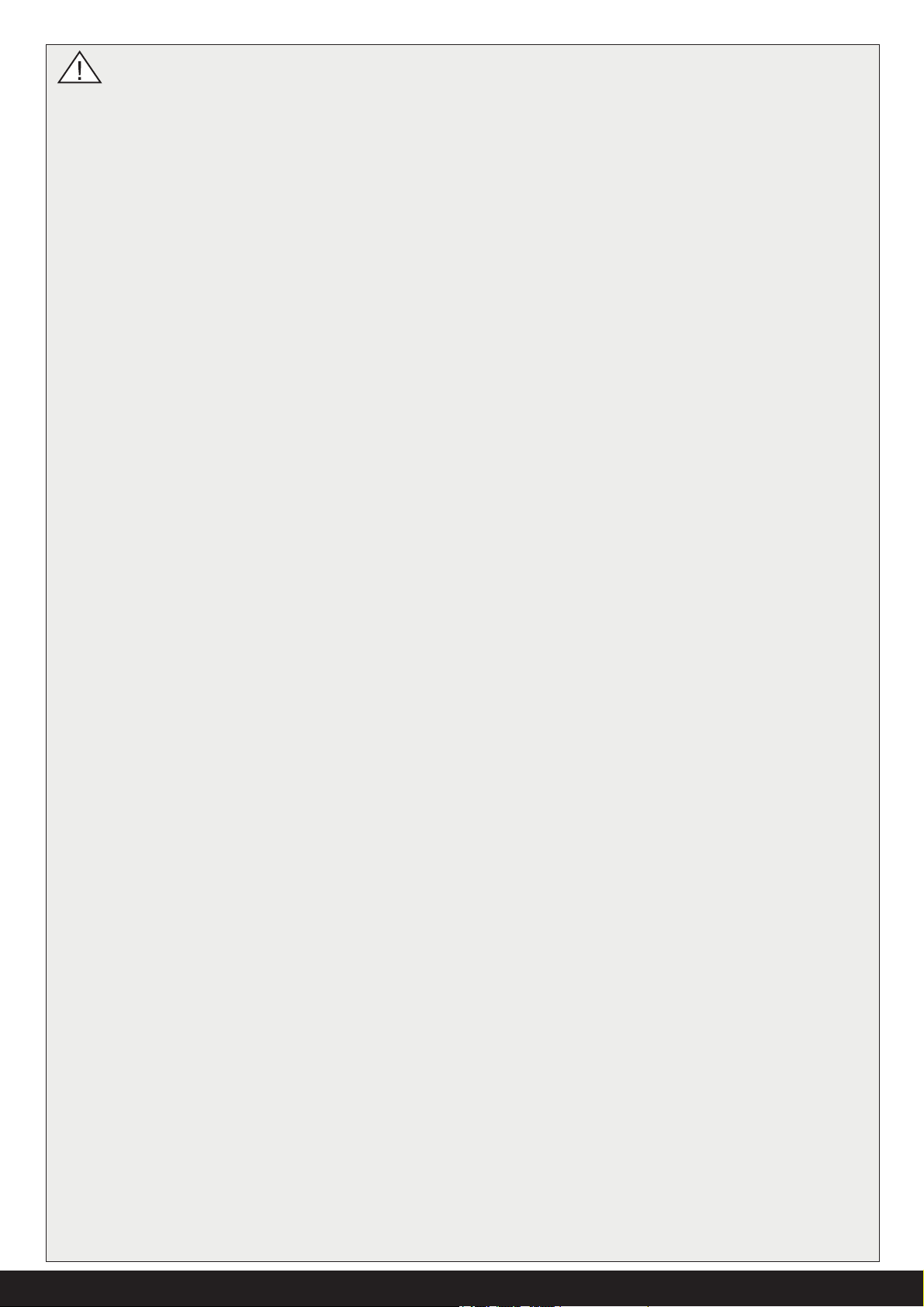
Figure 1: Sauna heater parts Sense Commercial 6-8
1. Sauna heater
2. Herb bowl/air humidifi er
3. Brackets x 4
4. Warning sticker in ten languages
5. Bracket screws x 4
6. Connectors x 3
7. Lock screw B8x9.5 x 1
2
4
3
1
5
6
Figure 2: Sauna heater parts Sense Commercial 10-20
1. Sauna heater
2. Brackets x 4
3. Warning sticker in twelve languages
4. Bracket screws x 4
5. Connectors x 3
6. Bracket screws/lock screw B8x9.5 x 9
Contact your dealer if anything is missing.
The following electronic control panels together with relay box
Commercial/Commercial Lite are compatible with Sense Commercial: Pure and Elite.
The following mechanical control panels are compatible with
Sense Commercial 6-8-10 kW: TS 16 and Sense Commercial 6-810-16 kW: TS 30.
See separate guides.
NOTE! A brick wall without heat insulation increases
the warm-up time. Each square meter of plastered
ceiling or wall surface equals an additional 1.2–2 m³
of sauna volume.
Table 1: Output and sauna volume
Output kW Sauna volume min./max. m³
6,6 4-8
8 6-12
10,7 10-18
16 15-35
20 22-43
DANGER! Poor ventilation or heater positioning
may lead to dry distillation, posing a fi re risk
under certain circumstances!
DANGER! Insuffi cient insulation of the sauna
cabin may pose a fi re risk!
DANGER! Use of the wrong materials in the
sauna cabin, such as particle board, drywall, etc.,
may pose a fi re risk!
DANGER! The heater must be connected by a
qualifi ed electrician pursuant to applicable regu-
lations!
Installation tools
The following tools and materials are needed for installation and
connection:
• water level,
• adjustable spanner,
• electric drill,
• screwdrivers.
Installation planning
Before starting to install your sauna heater:
• Plan the sauna heater positioning (see the Heater positioning
- normal installation section, page 14).
• Plan the control panel positioning (see the attached instructions for the control panel for allowable positioning).
• Plan the sensor positioning (see Figure 5, page 14 and Figure 7, page 15).
• Position the air intake vent (see the Air intake vent positioning
section, page 15).
• Position the air exhaust vent (see the Air exhaust vent positioning section, page 16).
• Plan the electrical installation (see the Connection/wiring
diagram section, page 19).
14
3
2
Positioning the heater - normal installation
DANGER! No more than one heater may be installed in the same sauna cabin.
Position the sauna heater:
• on the same wall as the door (or the side wall if very close
to the door wall). The heater may also be placed in a recess
(see Figure 7).
• Position the heater at a safe distance from the fl oor, side
walls and interior fi ttings (see Figure 5).
1
Position the sensor according the picture (see Figure 5).
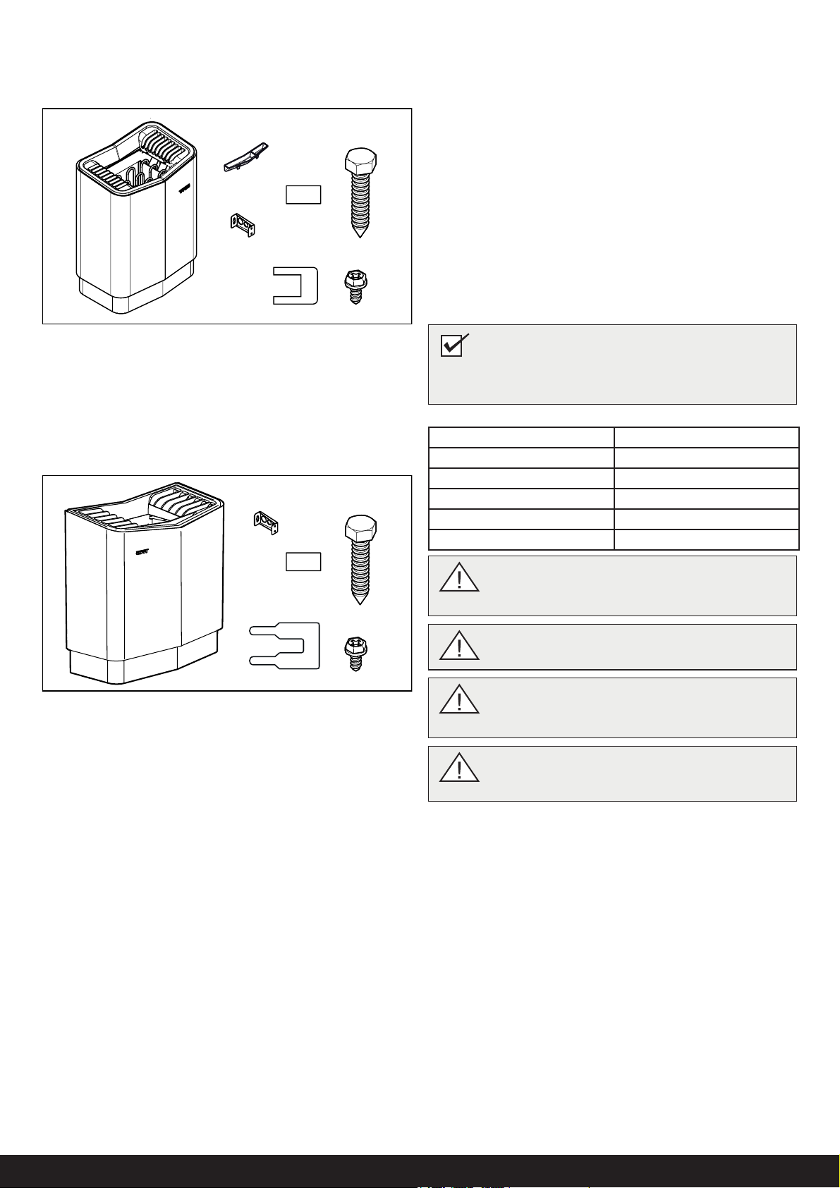
Figure 3: Schematic diagram of installation for control panel TS
16 and TS 30
1. Sauna heater
2. Control panel (placed outside the sauna)
3. Sensor (not extendable)
3
45
2
6
1
Figure 4: Schematic diagram of installation for control panel
Pure, Elite
1. Sauna heater
2. Control panel
3. Sensor (extendable)
4. External on/off switch (option, door contact needed for function)
5. Door contact (option)
6. Relay box RB Commercial/RB Commercial Lite (placed outside the sauna)
Control panel positioning (TS-panel)
The TS-panels are thermally controlled and have a patented divided eff ect. These should be installed on the wall or fi tted into
the wall.
If fi tted into the wall, there must always be insulation behind the
control panel. Capillary tube length 1850 mm. Also available with
capillary tube length 5000 mm.
6A
4
2
3
7
8
1
9
6B
5
10
11
3
12
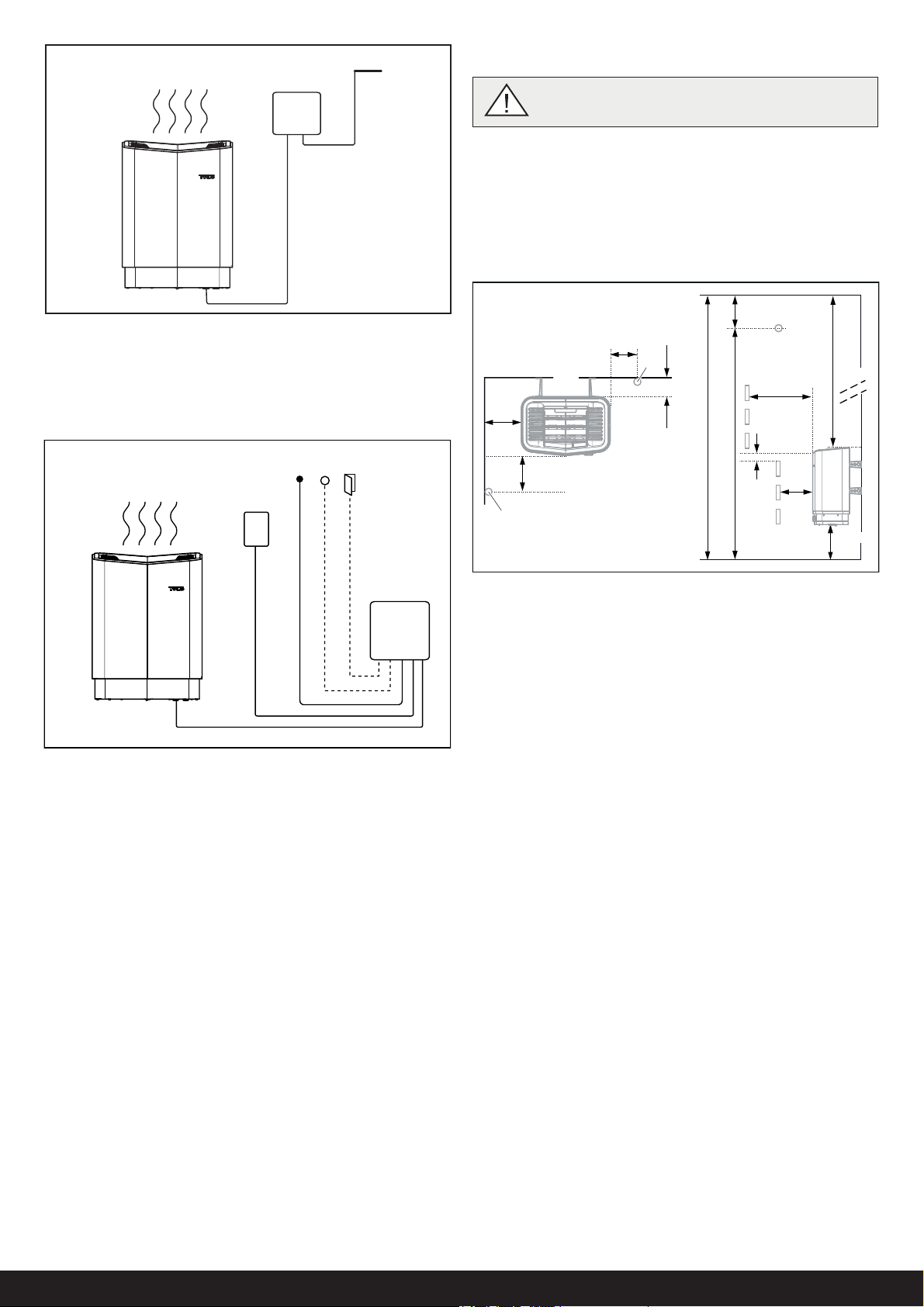
Figure 5: Positioning the heater - normal installation
1. Minimum distance from side wall:
Sense Commercial 6-8: 110 mm
Sense Commercial 10-16-20: 150 mm
2. Sensor position alt 1:
Sense Commercial 6-8: 300 mm from heater
Sense Commercial 10-16-20: 500-1500 mm from heater
3. Sensor
4. Minimum distance from back wall (Sense Commercial 6-8
with legs): 95 mm
5. Sensor position alt 2:
Sense Commercial 6-8: 300 mm from heater front
Sense Commercial 10-16-20: 500-1500 mm from heater
front
6. Sensor position:
6A. Sense Commercial 6-8: 150 mm from ceiling
6B. Sense Commercial 10-16-20: 1500 mm from fl oor
7. Minimum distance from ceiling:
Sense Commercial 6-8: 1030 mm
Sense Commercial 10-16-20: 1270 mm
8. Minimum distance from interior fi ttings:
Sense Commercial 6-8: 100 mm
Sense Commercial 10-16-20: 400 mm
9. Minimum ceiling height:
Sense Commercial 6-8-10: 1900 mm
Sense Commercial 16-20: 2100 mm
10. Minimum distance: 20 mm
11. Minimum distance from interior fi ttings:
Sense Commercial 6-8: 30 mm
Sense Commercial 10-16-20: 200 mm
12. Distance from fl oor: 270 mm (Sense Commercial 6-8 with
legs: 100 mm)
 Loading...