

Page 1
1311
ENGLISH
INSTALLATION GUIDE
SENSE COMBI
29005195 -ENG
Page 2

Keep this user guide!
In the event of any problems, please contact the retailer
where you purchased the equipment.
© This publication may not be reproduced, in part or in whole,
without the written permission of Tylö. Tylö reserves the right to
make changes in materials, construction and design.
TABLE OF CONTENTS
Before installation ..........................................................1
Parts .......................................................................................1
Installation requirements ........................................................ 1
Installation tools ..................................................................... 2
Planning installation ............................................................... 2
Installation ...................................................................... 4
Sauna heater installation ....................................................... 4
Installation of control panel ...................................................6
External ON/OFF switch (option) ...........................................7
Extra control panel (option) ....................................................7
Connection/wiring diagram ...........................................8
Checking installation ..................................................... 9
Page 3
1
BEFORE INSTALLATION
Parts
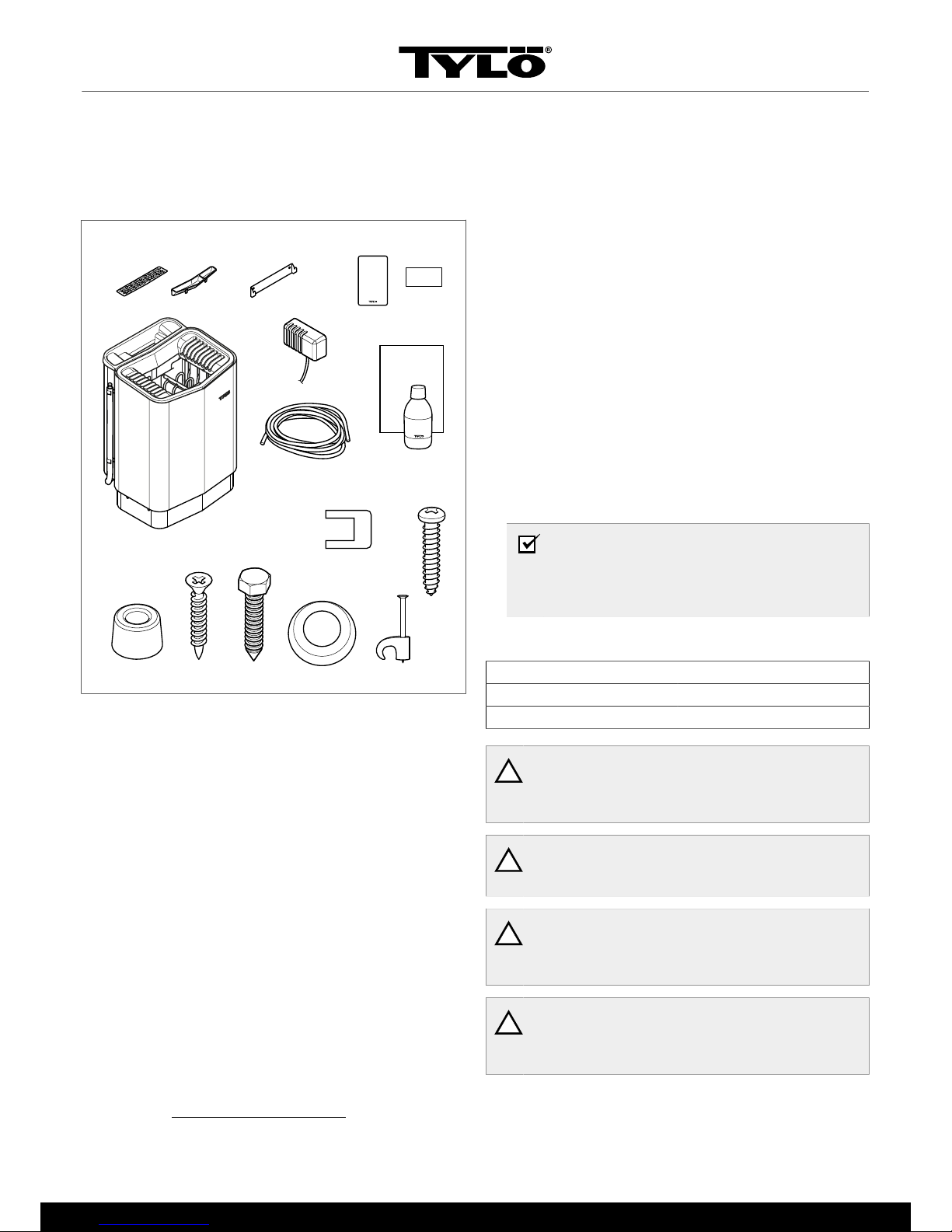
Check that the following parts are included in the packaging:
3
2
1
4
6
13
12
9
15
16
17
5
7
10
11
8
14
Figure 1: Sauna heater parts
1.
Sauna heater
2.
Herb bowl/air humidifier
3.
Herb bowl
4.
Brackets
5.
Sensor/temperature cut-out C-P, cable length 4 m
6.
Control panel
7.
Warning sticker in ten languages
8.
Cable between heater and control panel, 2-LIFYCY TP
2X2X0.2 mm² x 1
9.
Fragrance holder
10.
Sauna fragrance Lavender 10 ml x 1
11.
Spacers x 4
12.
Screws x 4
13.
Bracket screws x 2
14.
Connectors x 3
15.
Screws RXS/A2 PHIL B6x25 x 2 pcs
16.
Cable bushing Membrane 107-099 x 1
17.
Clips TC (5-7) x 10 pcs
Contact your dealer if anything is missing.
Installation requirements
For detailed instructions concerning sauna construction/ventilation etc., go to: http://www.tylö.se/byggabastu
and download this
document: "Building a sauna.pdf".
To ensure safe use of the heater, check that the following criteria
are met:
• The sauna cabin should meet the requirements for ceiling
height and dimensions according to: "Building a sauna.pdf".
• The sauna cabin should meet the requirements for insulation
and materials according to: "Building a sauna.pdf".
• Cable (EKK) or electrical ducting for connecting the heater
must be run on the outside of the heat insulation.
• Cable installation must be correctly performed (see The section called Connection/wiring diagram, Page 8).
• Fuse size (A) and power cable size (mm²) must be suitable
for the heater (see The section called Connection/wiring dia-
gram, Page 8).
• The sauna ventilation must comply with the instructions in this
manual (see The section called Positioning the inlet vent,
Page 3, The section called Positioning the outlet vent,
Page 4).
• The position of the sauna heater, control panel and sensors
must comply with the instructions in this manual.
• The heater output (kW) must be suitable for the sauna volume
(m³) (see Table 1, Page 1). The minimum and maximum
volumes must not be exceeded.
NOTE! A brick wall without heat insulation increases
the warm-up time. Each square metre of plastered
ceiling or wall surface equals an additional 1.2–2 m³
of sauna volume.
Table 1: Output and sauna volume
Output kW Sauna volume min./max. m³
6,6 4-8
8 6-12
!
DANGER! Incorrect ventilation or heater positioning
can lead to the wooden panels drying out, posing a
fire risk in certain circumstances.
!
DANGER! Insufficient insulation of the sauna cabin
can pose a fire risk.
!
DANGER! Use of the wrong materials in the cabin,
such as chipboard, plasterboard etc., can pose a fire
risk.
!
DANGER! The heater must be connected by a qualified electrician according to the applicable regulations.
Page 4
2
Installation tools
The following tools and materials are needed for installation and
connection:
• spirit level,
• adjustable spanner,
• electric drill,
• screwdriver.
Planning installation
Before starting to install your sauna heater:
• Plan where to position the sauna heater (see The section
called Positioning the heater - normal installation, Page
2).
• Plan where to position the control panel (see The section
called Positioning the control panel, Page 3).
• Plan where to position the sensor (see Figure 3, Page 2
and Figure 5, Page 3).
• Position the inlet vent (see The section called Positioning the
inlet vent, Page 3).
• Position the outlet vent (see The section called Positioning
the outlet vent, Page 4).
1
2 5
3 4
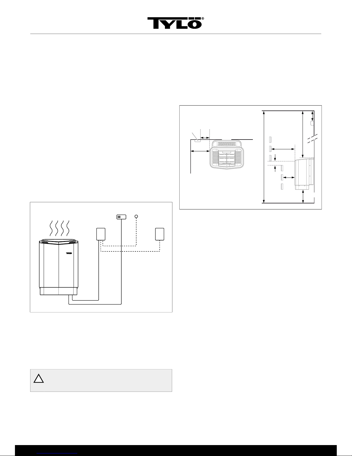
Figure 2: Schematic diagram of installation
1.
Sauna heater
2.
Control panel
3.
Sensor
4.
External on/off switch (option)
5.
Extra control panel (option)
Positioning the heater - normal installation
!
DANGER! More than one heater can be installed in
the same sauna cabin.
Position the sauna heater:
• on the same wall as the door (or the side wall if very close to
the door wall). The heater can also be positioned in a recess
(see Figure 5, Page 3).
• at a safe distance from the floor, side walls and interior fittings
(see Figure 3, Page 2).
Position the sensor according to the diagram (see Figure 3, Page
2).
1
6
9
8
10
2
4
3
7
5
Figure 3: Positioning the heater - normal installation
1.
Minimum distance from side wall: 110 mm
2.
Sensor position: 200 mm from heater
3.
Sensor
4.
Sensor position: 40 mm from ceiling, regardless of ceiling
height
5.
Minimum distance from ceiling: 1030 mm
6.
Minimum distance from interior fittings: 100 mm
7.
Minimum ceiling height: 1900 mm
8.
Minimum distance: 20 mm
9.
Minimum distance from interior fittings: 30 mm
10.
Distance from floor: 100-270 mm (with legs: 100 mm)
If the wall that the sensor is to be installed on is made of highly
heat absorbing material (e.g. concrete, brick) or of toughened
glass, the sensor can be installed directly above the heater
(above the centreline of the heater as seen from the front and
side see Figure 4, Page 3).
Page 5

3
1
Figure 4: Sensor installation on ceiling on centreline of heater as
seen from the front and side
1.
200 mm
Positioning the heater - recess installation
To position the sauna heater in a recess:
1. Position the heater at a safe distance from the floor, side walls
and interior fittings (see Figure 5, Page 3).
2. Position the sensor according to the diagram (see Figure 5,
Page 3).
7
10
9
11
1
4
1
5
2
3
8
6
Figure 5: Positioning the heater - recess installation
1.
Minimum distance from side wall: 200 mm
2.
Sensor position: 200 mm from heater
3.
Sensor
4.
Max. 1000 mm
5.
Sensor position: 40 mm from ceiling, regardless of ceiling
height
6.
Minimum distance from ceiling: 1030 mm
7.
Minimum distance from interior fittings: 100 mm
8.
Minimum ceiling height: 1900 mm
9.
Minimum distance: 20 mm
10.
Minimum distance from interior fittings: 30 mm
11.
Distance from floor: 100-270 mm (with legs: 100 mm)
Positioning the control panel
The control panel must be correctly positioned with regard to
safety distances.
1
2
4
3
Figure 6: Safety distance, control panel
1.
Heater
2.
Control panel
3.
Max. 900 mm
4.
Min. 300 mm
Positioning the inlet vent
Install the inlet vent straight through the wall under the centreline
of the heater. Vent size for a family sauna approx. 125 cm².
The air circulation from the door must concord with the hot air circulation from the heater.
Page 6

4
1 2
3 4
Figure 7: Positioning the inlet and outlet vents
1.
Inlet vent position.
2.
Outlet vent position through the sauna wall.
3.
Outlet vent position through the cavity.
4.
Outlet vent position via duct.
Positioning the outlet vent
!
DANGER! The outlet vent must not lead outdoors.
This could cause the ventilation direction to be reversed, which may negatively affect the heater temperature cut-out.
!
DANGER! Any gap above the sauna ceiling should
not be sealed without leaving at least one vent hole
on the same wall as the sauna door.
Position the outlet vent
• at the maximum possible distance from the inlet vent, e.g. diagonally (see Figure 7, Page 4).
• high on the wall or in the ceiling (see Figure 7, Page 4).
• so that it vents into the space the door and inlet vent open into.
The outlet vent must have the same area as the inlet vent.
Ensure that the outlet vent is open.
Mechanical ventilation is not recommended due to the risk of poor
air exchange, which can negatively affect the heater temperature
cut-out.
INSTALLATION
Sauna heater installation
It is easiest to prepare for installation with the heater lying down.
To install the heater:
1. Lay the heater down front upwards.
2. Slacken the screws and open the cover (see Figure 8, Page
4).
Figure 8: Opening/closing the cover
3.
!
WARNING! Always check that the heater is connected to the correct main/phase voltage.
Connect the heater using standard wiring (Fk or EKK) approved for fixed installation.
Any single wires (Fk) must be protected in electrical conduits
(VP) to the heater.
Page 7

5
Connect the electrical cable (1) to terminal (2) (see Figure
9, Page 5) according to wiring diagram (see The section
called Connection/wiring diagram, Page 8).
7435
1
28
6
Figure 9: Circuit board
1.
Electrical cable
2.
Terminal for connection of electrical cable
3.
Control panel cable
4.
Terminal for connection of control panel
5.
Sensor cable
6.
Terminal for connection of sensor
7.
Light cable (if relevant)
8.
Terminal for connection of light (if relevant)
4. Connect the control panel cable (3) to terminal(4) (see Figure
9, Page 5) according to wiring diagram (see The section
called Connection/wiring diagram, Page 8).
5. Connect the sensor cable (5) on the terminal (6) (see The
section called Connection/wiring diagram, Page 8) according to the wiring diagram (see The section called Con-
nection/wiring diagram, Page 8).
6. Connect light cable (if relevant) (7) see Figure 9, Page 5
to terminal (8) according to the wiring diagramFigure 19,
Page 8.
7. Close the cover and tighten the screws (see Figure 8, Page
4).
8. Attach the bracket and spacers to the wall following the specified dimensioning (see Figure 10, Page 5).
1
2
3
3
4
Figure 10: Bracket with screws and spacers
1.
760 mm
2.
280 mm
3.
185 mm
4.
230 mm (minimum distance)
9. Hang the heater on the bracket (see Figure 11, Page 5).
Figure 11: Hang the heater up.
Page 8

6
10. Fit the spacers between heater and wall (to prevent the heater
from being lifted off) (see Figure 12, Page 6).
Figure 12: Fit spacers
11. Fit the cover for the water reservoir, herb grille and fragrance
holder/air humidifier (see Figure 13, Page 6).
Figure 13: Fitting the cover for the water reservoir, herb grille
and fragrance holder/air humidifier
12. Install the sensor on the wall see Figure 14, Page 6.
Tighten the screws carefully to avoid breaking the circuit
board.
Figure 14: Installing the sensor
Unusual voltages/numbers of phases
Before connecting to voltages or numbers of phases not listed in
the wiring diagram Figure 19, Page 8, contact Tylö Customer
Service.
Installation of control panel
The control panel can be installed inside or outside the sauna. If
installing it inside, the upper edge must not be more than 90 cm
from the floor. Use a type 2-LIFYCY 2X2X0.2 mm Twisted Pair
cable to connect control panel to heater.
To install the control panel:
1. Slacken the lock screw and split the panel and back piece
(see Figure 15, Page 6 pos 1).
2
5
3
6
4
1
Figure 15: Installing the control panel
1.
Slacken the lock screw
2.
Seal
3.
Mounting on wall
4.
Terminal
5.
Slide on the panel's glass element
6.
Tighten the lock screw
2. Glue the seal onto the back piece (see Figure 15, Page 6
pos 2).
3. Mount the back piece leaving sufficient room for electrical
cables to pass through their openings. Note that the hole for
the retaining screw must be at the bottom (see Figure 15,
Page 6 pos 3).
Page 9

7
Alternative cabling: e.g. external cabling: drill a small hole in
the bottom edge of the plastic cover for external cabling, for
the cable to go into the wall (see Figure 16, Page 7).
Figure 16: Alternative cabling
4. Screw the wires onto the terminals according to the wiring dia-
gram (see Figure 15, Page 6 pos 4). To simplify connection, the long terminal can be removed from the circuit board
when screwing on the wires. Pull the terminal straight out, do
not bend it to avoid damage (see Figure 15, Page 6 detailed picture.
5. Slide on the control panel glass element from the bottom, and
hold in place (see Figure 15, Page 6 pos 5).
6. Tighten the lock screw in the bottom edge (see Figure 15,
Page 6 pos 6).
External ON/OFF switch (option)
The external ON/OFF switch can be positioned at any distance
from the control panel.
Connect the switch using low voltage wire (see Figure 17, Page
7 pos 4).
1
2
3 4 5 6
Figure 17: Wiring diagram for external ON/OFF switch
1.
h2
2.
External ON/OFF switch (option)
3.
Red
4.
White
5.
Black
6.
Black
Additional ON/OFF switches must be connected in parallel. Several individual units can be started or stopped via a single external switch.
NOTE! The control panel can also be connected to other appliances which give impulse or constant activation.
Terminal (-)21 is for indication - e.g. to show users status on the
control panel (built-in to Tylö external switches/impulse). The
function for this is:
• When the heater is unprogrammed: No diode lit. When
pressed, the heater will go to On and a steady diode light will
show on the external switch.
• When the heater is programmed but Off. The diode will flash
slowly. When pressed, the heater will start. The diode will
show a steady light.
• When the heater is in Standby-program: The diode will flash
rapidly. When pressed, the heater will switch from Standby
to On, and the diode will be on constantly. Indication must
be connected between (+)19 and (-)21, (3 V/DC max 0.3W
100mA).
Extra control panel (option)
Extra control panels (h2) can be connected as an option.
!
WARNING! When installing an extra control panel,
the heater must be disconnected from the mains.
After an extra panel has been connected, reconnect
to the mains and the system is ready for use.
The control panel can be connected in serial from terminal A or
B on the panel to A or B on the extra panel. Voltage can be connected from terminal +11 and -12 on the control panel to terminals +11 and -12 on the extra panel (see Figure 18, Page 7).
12
11BA
12
11BA
12
11BA
1 2 3
*
*
*
*
* 4
Figure 18: Wiring diagram, extra control panel
1.
Heater
2.
Control panel
3.
Extra control panel
4.
4 x 0.2 mm² (AWG 24), serial connection
Page 10

8
CONNECTION/WIRING DIAGRAM
Output kW Voltage Amperage Wiring area mm²
6,6 400V 3N~ 10 1,5
8 400V 3N~ 12 2,5
1
1
7
7
3
2
3
5
5
4
6
1 2 3 4
Figure 19: Wiring diagram
1.
Heater
2.
Terminal for connection of electrical cable
3.
Control panel
4.
Terminal for connection of control panels
5.
Sensor/sensor cable
6.
Terminal for connection of sensor
7.
Light/terminal for connection of light
Page 11

9
CHECKING INSTALLATION
To check the installation:
1. Switch heater on (see User Guide).
2. Check that the control panel lights up .
3. Start the heater (see User Guide).
4. Check that all three tubular elements start to heat up (go red).
Page 12

 Loading...