

Page 1
Precautions to be taken before commissioning
2
Pre-assembly information
2
Electrical requirements
2
Cabin construction/ assembly
3
Junction box connections
3
Main junction box connections
6
Power connections on the ceiling
8
Control panel instructions
10
Lighting: Internal/ external/ colour therapy
11
Maintenance & technical support
11
Wiring diagram
12
121210
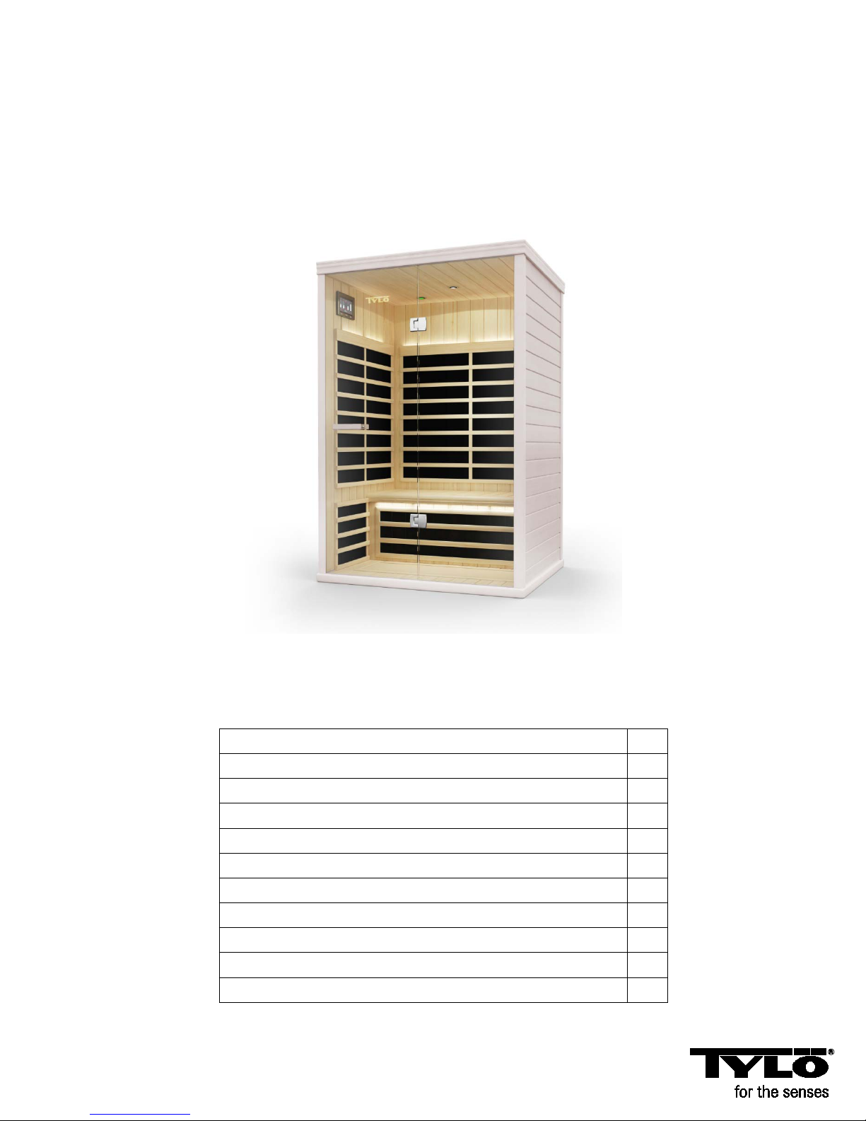
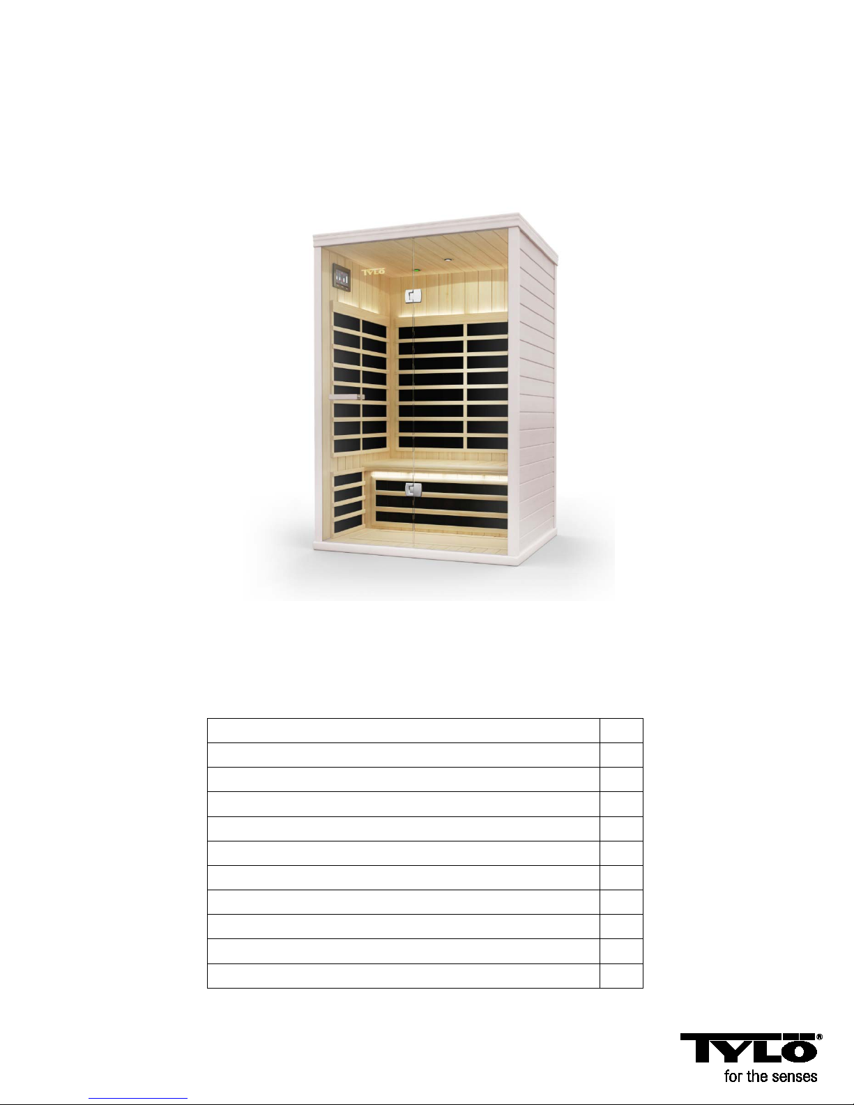
2 person infrared sauna
Prime+ 1210
User manual
Note: The cabin must be installed on a flat, level surface.
Page 2

Precautions to be taken before commissioning Warning (space configuration and use):
• Correct electrical earthing is required
• Electrical sockets are not permitted in the sauna.
• Do not allow heating elements to come into contact with water.
• Do not fit a lock or bolt on the door.
• Do not block the ventilation holes.
• Children must always be supervised in the sauna.
• Clean the sauna with a damp cloth.
• Cleaning the sauna with steam cleaners, high pressure cleaners or spraying with water is not permitted.
Electrical warning – “Do not insert the sauna power cable into a socket before assembly is complete.”
Warning (human restrictions):
• Being exposed to high temperatures for a long time may lead to hyperthermia (body temperature is several
degrees above 37° Celsius)
• Hyperthermia symptoms include: dizziness, lethargy, grogginess and feeling faint. Effects of hyperthermia:
o Failure to realise that you have to leave the infrared sauna.
o Damage to the foetus in pregnant women.
o Being physically unable to leave the sauna.
o Loss of consciousness
• Warning – the consumption of alcohol or drugs increases the risk of fatal hyperthermia.
• If you have health problems or are ill, consult your doctor before using the sauna.
• Stop using it immediately if you feel restless, if you start shaking, if you have a headache or feel sick or
nauseous.
• People who suffer from hyperthermia or cardiovascular diseases should seek medical advice before using
the infrared sauna.
• Do not use a sauna if you have drunk alcohol or taken tranquillisers or if you suffer from pain in the heat.
• Using the infrared sauna is not advisable if you have been exposed to UV radiation (a solarium or been
sunbathing) in the last 24 hours.
• Should you notice unusual skin changes after using the infrared sauna e.g. persistent erythema (reddening
of the skin for more than one day) or a reticular change in colour, you should stop using it and seek medical
advice.
Warning (fire risk):
• Do not use the sauna to dry clothing, bathing costumes etc.
• Do not hang towels or other objects on or in front of the infrared heat radiator.
• Never operate the infrared sauna with a damaged cable or a damaged socket.
Pre-assembly information:
a. Two (2) adults are required for assembling and installing the sauna.
b. Assembly tools: Phillips screwdriver
c. The boxes are labelled in order of assembly.
d. Note: The glass for assembling the front wall panel is heavy and fragile.
Box 1: Floor, ceiling, bench valance, bench, fan component and manual
Pack of 10 Phillips screws for the junction box covers
Door handle set
Box 2: Back and front wall panels
Box 3: Left and right wall panels
Electrical requirements: The infrared sauna must have a 230 volt connection.
Page 2
Page 3
How to construct the sauna:
Note – there are 11 power connections in all and several low voltage connections.
(7) are in the sauna: (back, left and right) panels, bench valance, bench valance fan,
bench and main power connection.
There are additional power connections on the top outer face of the ceiling.
(1) Mains connection cable for the sauna. Do NOT insert the main electrical connection
cable for the sauna into the socket before all the assembly steps have been
completed correctly.
------------------------------------------------------------------------------------------------------------------------------------------------
There are (5) power connection/ junction boxes that are labelled accordingly and must be connected
after assembling each section.
Back wall panel Left Right Bench valance Bench
B1 to B1 L1 to L1 R1 to R1 S3 to S3 S1 to S1
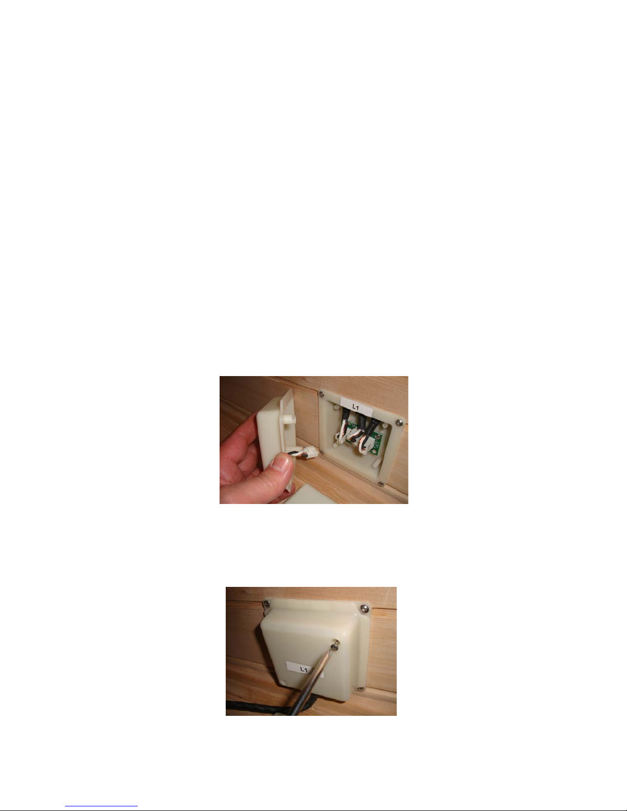
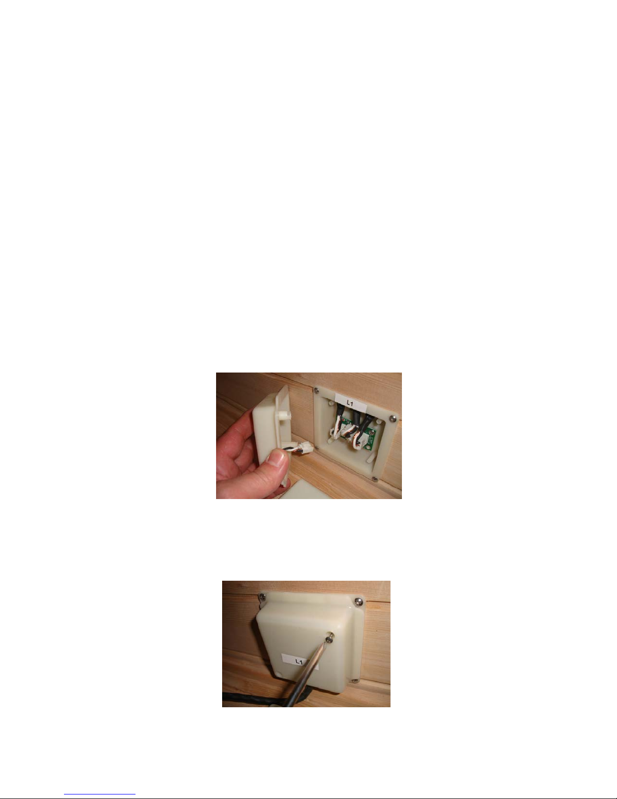
These (5) power plugs are connected easily by simply inserting the white plug of the white junction
box cover into the correct plug-in connection (3) in the junction box.
Example below: L1 to L1 (left wall panel power connection) (left wall panel junction box)
Fitting the junction box covers: After the junction box has been connected securely fix the junction
box cover with a Phillips screwdriver and 2 Phillips screws from Box 1.
Page 3
Page 4
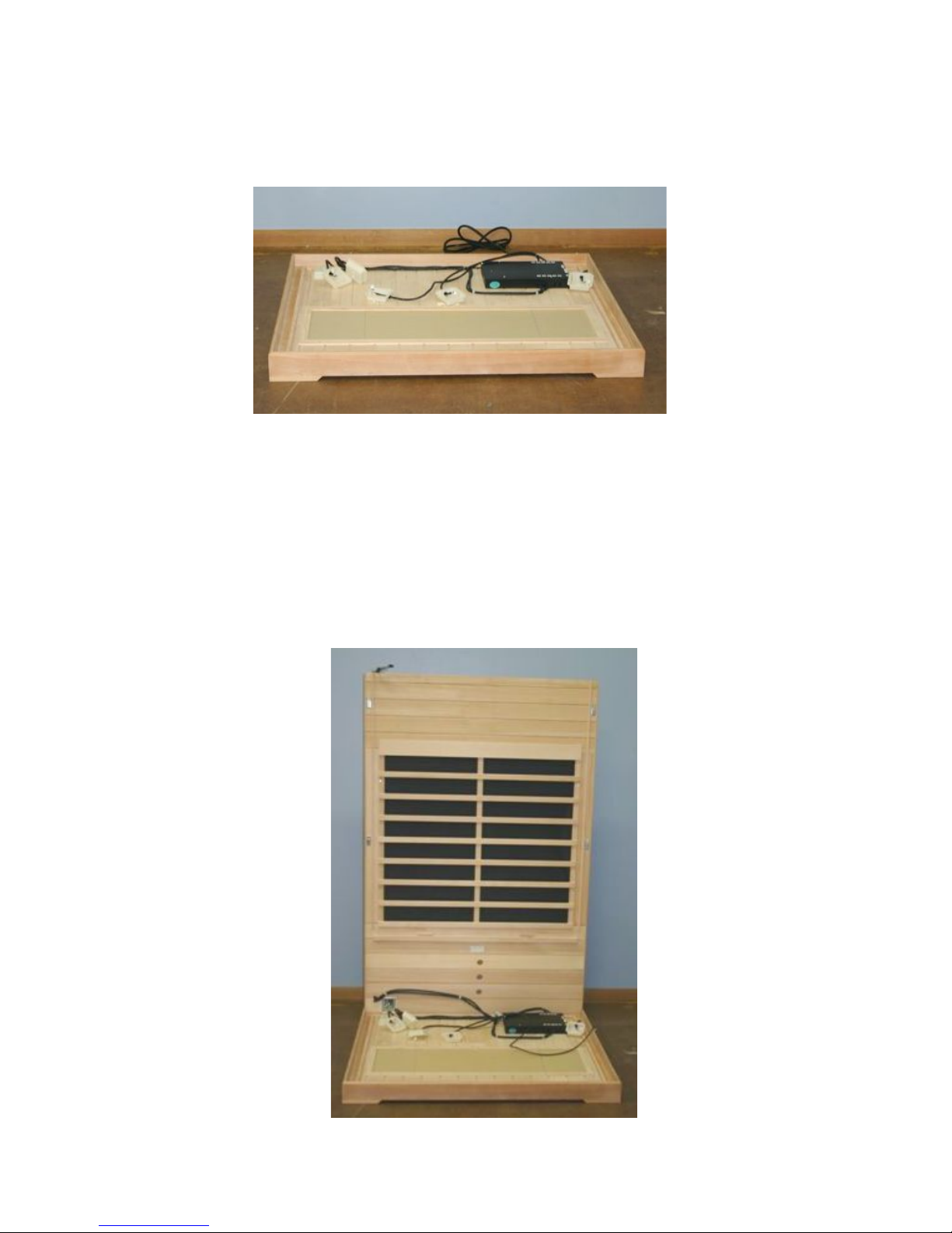
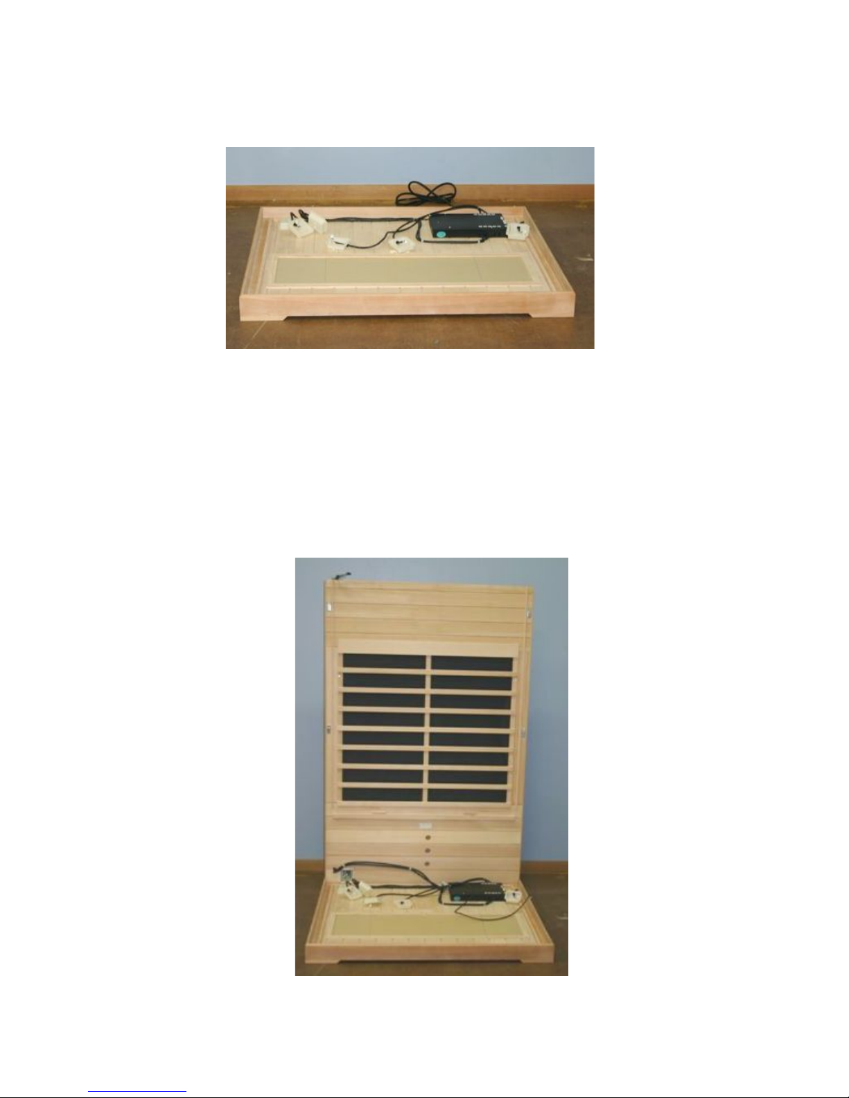
Floor panel (Box 1): Put the floor panel on a level surface 8-16 cm from the wall panel and no more
than 152 cm away from a 230V socket.
Position the floor panel in such a way that the ceramic tiles/ IR floor heating point towards the front
of the sauna.
Note: Put the ceiling, bench valance and bench aside until the corresponding steps.
Rear wall panel (Box 2):
• Place the rear panel section into the rear slot on the floor panel.
• The back wall panel section must be held upright until the right wall panel is fitted.
• Connect the electrical supply to the B-1 junction box.
• Fix the cover of the B-1 junction box with 2 Phillips screws.
Note – Put the front panel aside until the “Front panel” section.
Page 4
Page 5

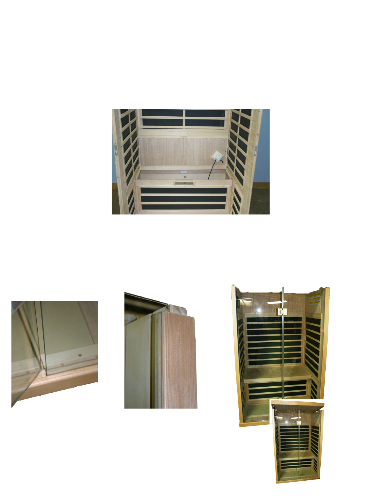
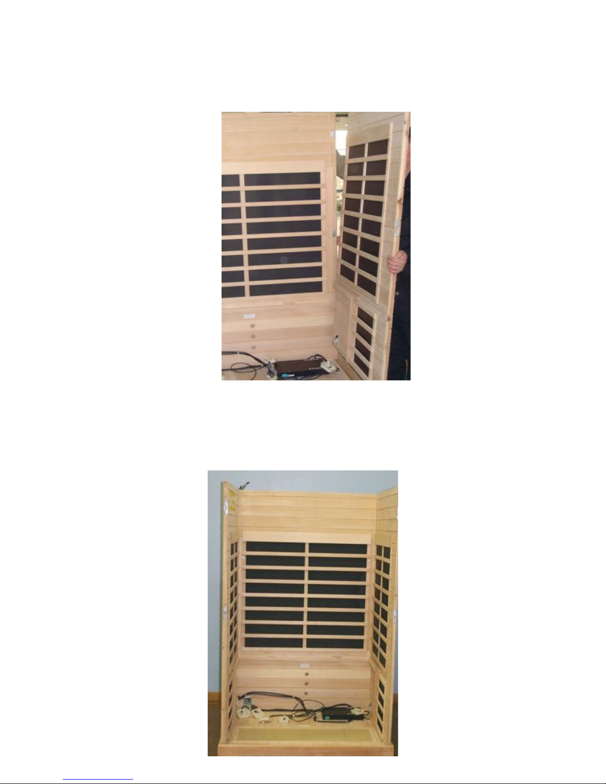
Right wall panel (Box 3):
• Place the right wall panel into the right hand slot on the floor panel.
• Attach the back wall panel to the right wall panel by lifting the right panel and pushing
it into the retaining bracket on the back panel.
• Connect the R-1 electrical supply to the R-1 junction box.
• Fix the cover of the R-1 junction box with 2 Phillips screws.
Left wall panel (Box 3):
• Place the left wall panel into the left hand slot on the floor panel.
• Attach the back wall panel to the left wall panel by lifting the left panel and pushing
it into the retaining bracket on the back panel.
• Connect the L-1 electrical supply to the L-1 junction box.
• Fix the cover of the L-1 junction box with 2 Phillips screws.
Page 5
Page 6

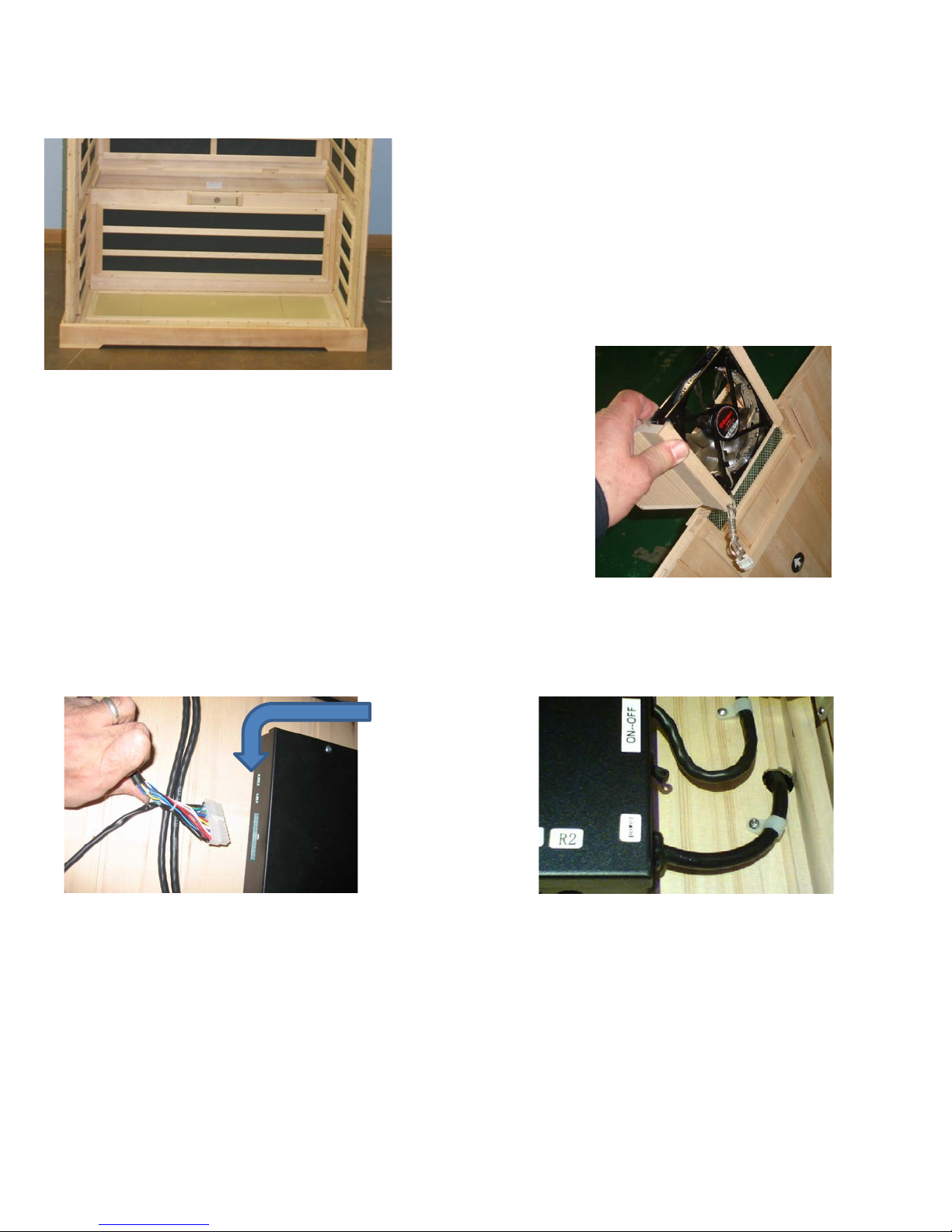
Bench valance (Box 1):
• Insert the bench valance between the left and right wall panel sections.
• Connect the S-3 electrical supply to the S-3 junction box.
• Fix the cover of the S-3 junction box with 2 Phillips screws.
Slide the fan component (Box 1) into
the support on the bench valance.
Connect the white connection on the black
junction box to the white connection on the fan.
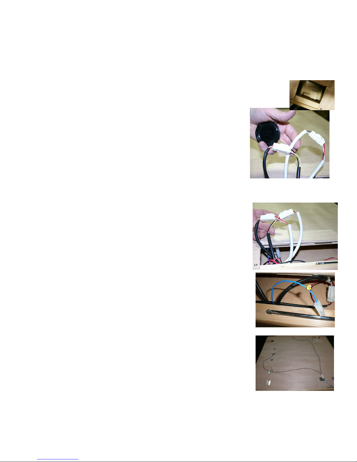
Black main junction box: (2) connections
Locate the black main junction box that is fixed to the internal floor of the sauna.
1 Insert the 24 pin, multicoloured cable plug into the left hand side of the main junction box.
See point 3 Input/output
2 The ON/ OFF switch is on the right hand side of the main junction box.
Set the switch as shown above to the ON (EIN) position.
3 Connect the loudspeaker input and output.
Note – Do NOT insert the 230 volt alternating current cable into the socket yet.
Page 6
Page 7
Bench (Box 1):
• Push the bench seat downwards into the back panel with the junction box
pointing towards you.
• Tilt the bench against the back panel as shown below.
• Connect the S-1 electrical connector to the S-1 junction box.
• Fix the cover of the S-1 junction box with 2 Phillips screws.
• Connect the bench valance strip lights to the strip light connection in the connector
(Note: two connections may come out of the floor with some models. You only
need to connect one with this model.)
• Lay the bench down and push it into the right place.
Front panel (Box 2):
• Push the front and glass sections into the corresponding slot in the floor.
Note: Only the right glass section will be fitted into the floor slot at this time. Push both side
panels to help secure the front wall panel.
Note: All panel parts are now connected but not secured.
Note: The ceiling is the final connection to secure the top end of the front panel.
Page 7
Page 8
Ceiling (Box 1):
Ceiling to the rear panel: (2) connections:
• Lift the ceiling up and place it carefully on the four (4) panels as shown below.
• Note: Ensure that the electrical connections are placed through the ceiling and are not disconnected
when you put the ceiling into position slowly.
• Tip: To make it easier to pull cables through the ceiling slot, you can take small styropor blocks and
put them on several places between the ceiling and the panels so that the ceiling stays put. When the
cables have been pulled through, remove the styropor blocks and lower the ceiling onto the panels.
• Using a step ladder, open the flaps in the ceiling and turn the wooden support 90º. This fixes the
ceiling securely onto the panels and ensures that the door panel cannot fall out.
Lift the door panel on the top left of the rear external face
of the ceiling. You will see 4 connections labelled 1–4.
Connect the ceiling connections 1–4 to connections
1–4 on the rear panel.
Ensure that the connections are firmly connected.
After connection close the back access panel.
Connection between the ceiling and the front wall panel:
• Lift the door on the top of the ceiling.
You will see four connections.
Note: Connect white to black on the two black and white cables.
• Connect the other 2 connections matching the colours.
• Numbered 5, 6, 7 & 8. Connect numbers 5–8 to 5–8.
• Close the front ceiling flap.
A dipole radio antenna is supplied with your infrared sauna for better
FM reception.
You will find the dipole antenna in the bag in the installation manual.
1. Take the dipole antenna (black wires) out of the bag in the
installation manual.
2. Open the cover on the top of the ceiling above the touch screen.
3. Connect the dipole antenna to the wire marked 7
4. Spread the wire out and pull it apart to improve FM radio reception.
Page 8
Page 9
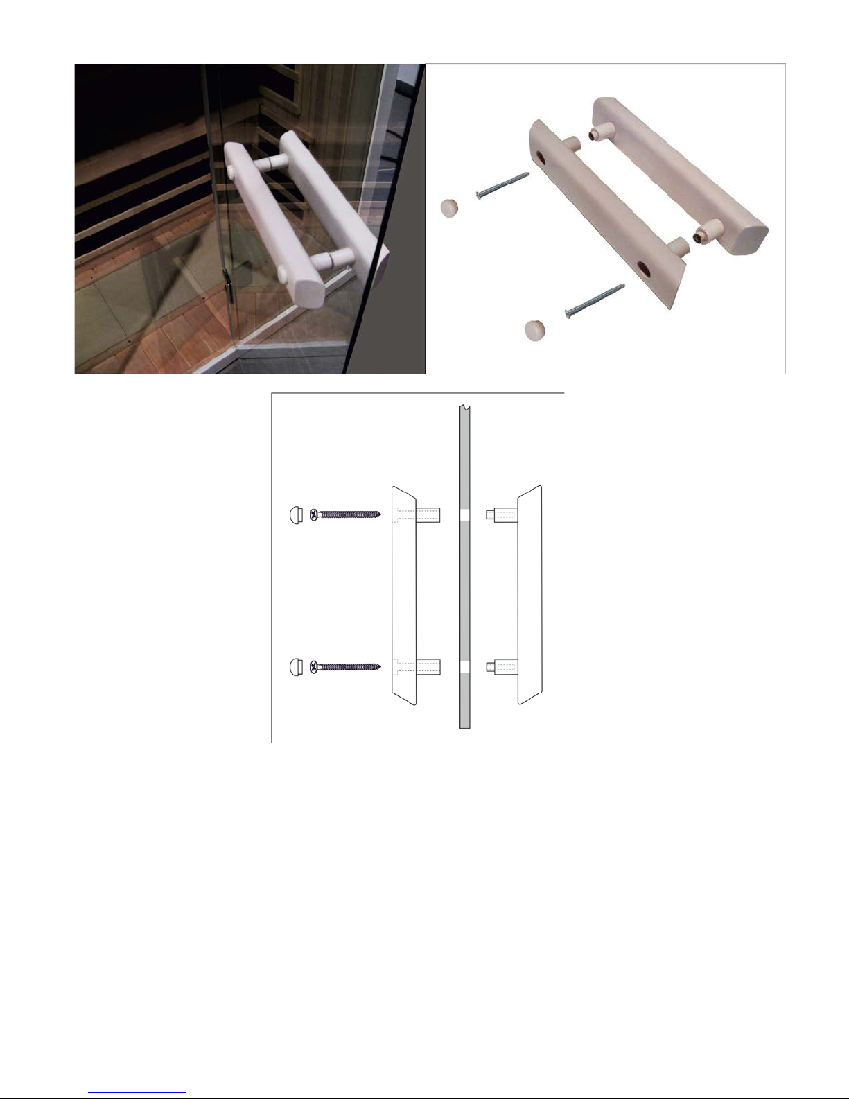
Door handles:
Inside Outside
Your infrared sauna is now ready for use.
------------------------------------------------------------------------------------------------------------------------------------------------
Page 9
Page 10
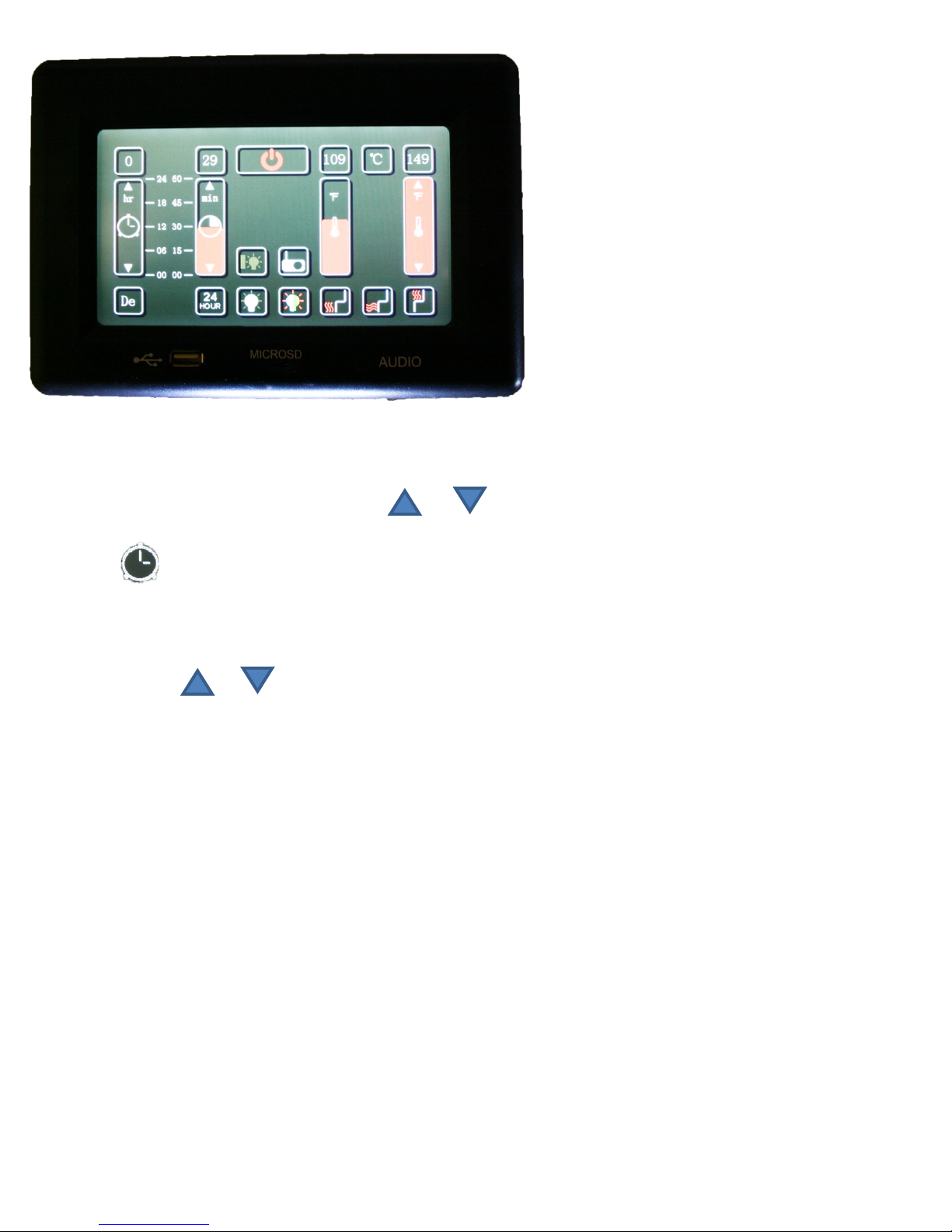
Control panel instructions:
Main current:
is ON. If it is white the sauna is OFF.
Press POWER to turn the sauna ON (AN) or OFF (AUS). If a red light comes on the sauna
Timer functions: Press and hold down or in order to set the running time. You can also run
your finger up or down the timer to set it.
Timer 2: Use this function with a pre-setting of up to 24 hours to set the sauna to come on later.
Temperature functions:
1. Press to switch between C and F. C or F will light up to show the required units.
2. Press and hold or to set the required temperature.
Pressing once will increase or reduce the setting in one degree intervals. You can also run your finger over
the temperature bar.
The central temperature display shows the actual sauna temperature.
3. Press to set the bench/ leg/ floor heat to ON or OFF . Red waves can be seen in heating mode and
white ones in OFF mode.
Light functions:
1. Press Inside light to switch it ON or OFF .
2. Note: Outside light ON or OFF will not work with S series models.
Colour therapy functions:
Press the colour therapy light in order to activate coloured light or a colour sequence. The sequence is
shown in detail below:
1. Press – RED
2. Press – RED-GREEN
3. Press – GREEN
4. Press – BLUE-GREEN
5. Press – BLUE
6. Press – BLUE-RED
7. Press – BLUE-RED-GREEN
8. Press – Activates the full rotation of all the 7 aforementioned colour therapies one after the other.
Page 10
Page 11
9. Press – Turns the colour therapy functions OFF.
Note: The colour of the light is indicated by the waves around the bulb symbol.
Troubleshooting tips:
a. Main control panel lights not lit up:
Check the electrical connections between the ceiling and the back wall panel and the front wall panel.
Ensure that the plug is correctly connected to the socket and the switch.
Ensure that the main switch (house) is not switched off (socket has power).
Ensure that the main control switch (under the bench) is not switched off and is ON.
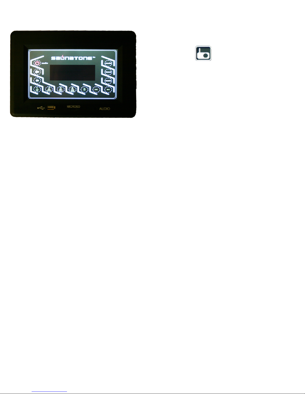
How to operate the radio and MP3 player
Press the radio icon to switch to radio mode.
Internal reception (only FM) varies. You can use USB,
micro SD or audio cable for MP3. You will have to use
an audio cable from your device for Apple products.
Loudspeakers are hidden sound generators. Some MP3
versions or other audio files can't be played back in the
USB or micro SD slot.
b. The sauna does not heat up:
Ensure that the power cable is correctly inserted into the socket.
Ensure that all junction boxes are correctly connected under the bench as shown
in the junction box connection code in 4a.
Ensure that the main switch (house) is not switched off (socket has power).
Ensure that the main control switch (under the bench) is not switched off and is ON.
Ensure that the required temperature is higher than the actual sauna temperature.
(Control needs heat)
-------------------------------------------------------------------------------------------
Page 11
Page 12
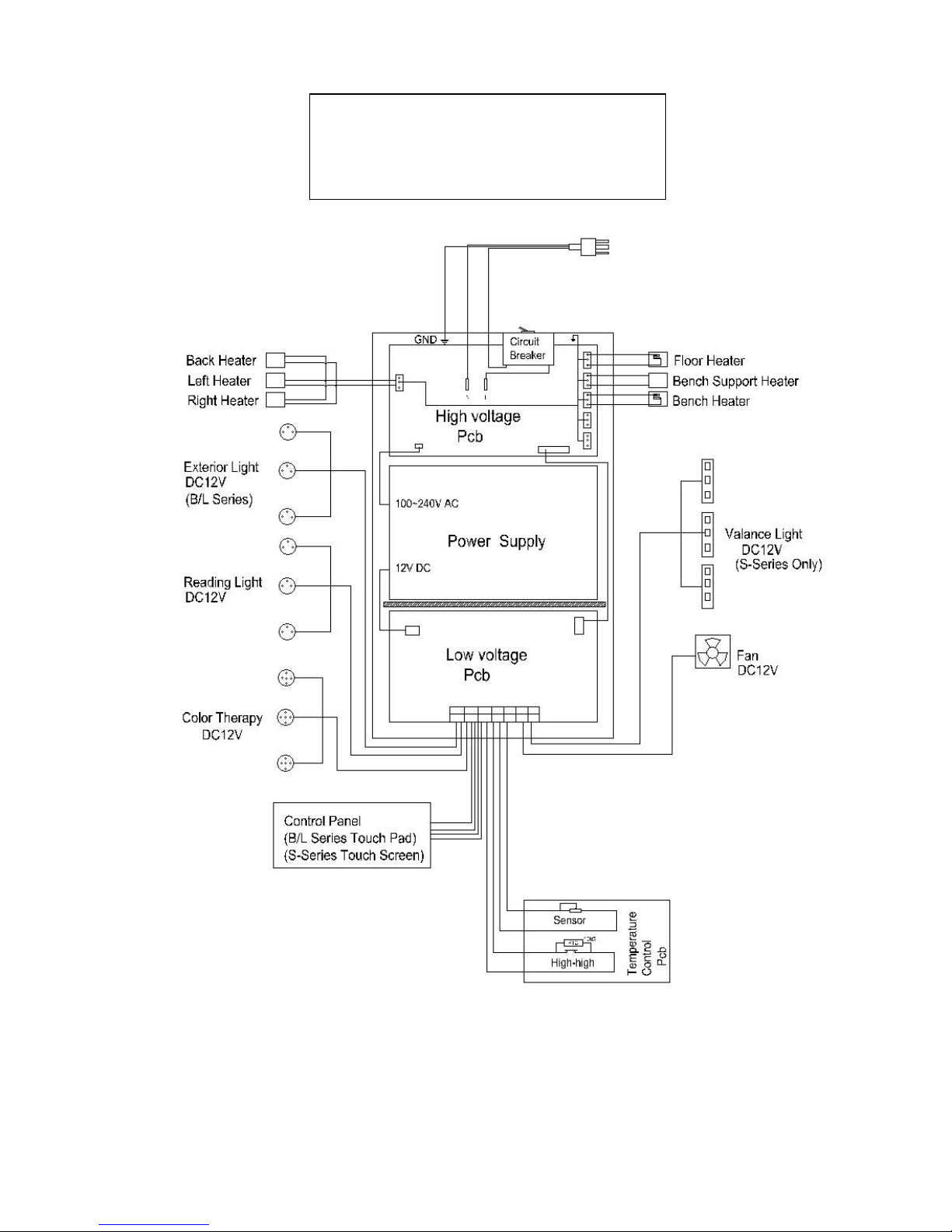
Wiring Diagram
Page 12
Page 13
Försiktighetsåtgärder innan kabinen tas i drift
2
Information om förmonteringen
2
Elkrav
2
Montera kabinen
3
Anslutningar i fördelningslådan
3
Anslutningar i huvudfördelningslådan
6
Elanslutningar i taket
8
Instruktioner för kontrollpanelen
10
Belysning: inne/ute/färgterapi
11
Underhåll och teknisk support
11
Kopplingsschema
12
121210
Infravärmekabin för två personer
Prime+ 1210
Användarinstruktioner
Anm.: Kabinen måste installeras på en plan, jämn yta.
Page 14

Försiktighetsåtgärder innan kabinen tas i drift: Varning (konfigurera och använda utrymmet):
• Riktig elektrisk jordning krävs
• Det är inte tillåtet att montera elkopplingar inuti kabinen
• Värmelementen får inte komma i kontakt med vatten
• Montera inte lås eller regel på dörren
• Blockera inte ventilationsöppningarna
• Barn får inte lämnas utan uppsyn i värmekabinen
• Rengör värmekabinen med en fuktig trasa
• Det är inte tillåtet att rengöra kabinen med ångrengöraring, högtrycksrengöring eller genom att spruta
av den med vatten
Elvarning – Anslut inte kontakten till elnätet förrän utrymmet är helt färdigmonterat!
Varning (användarbegränsningar):
• Om du är utsatt för förhöjda temperaturer över längre tid kan det leda till hypertermi (att kroppstemperaturen
ligger flera grader över 37 °C)
• Symtom på hypertermi är bland annat: yrsel, håglöshet, medtagenhet och svimning. Effekter av hypertermi:
o Användaren förstår inte att det är nödvändigt att lämna infrakabinen
o Fosterskador hos gravida
o Fysisk oförmåga att lämna utrymmet
o Medvetslöshet
• Obs! Med intag av alkohol eller droger ökar risken för dödlig hypertermi
• Om du har hälsoproblem eller sjukdomar bör du rådfråga läkare innan du använder värmekabinen
• Avbryt användningen direkt om du känner dig nervös, skakig, får huvudvärk, blir illamående eller kräks
• Personer som lider av hypertermi eller av hjärt-kärlsjukdom bör rådfråga läkare innan de använde
infravärmekabinen
• Använd inte värmekabinen om du har druckit alkohol eller tagit lugnande medel, eller om värme leder till
smärtor
• Vi rekommenderar inte att du använder infravärmekabinen om du under det senaste dygnet varit utsatt för
UV-strålning (om du solat ute eller i solarium)
• Om du upptäcker ovanliga hudförändringar efter att ha använt infravärmekabinen, till exempel långvarigt
erytem (hudrodnad som kvarstår mer än en dag) eller nätartade färgförändringar, ska du avbryta
användningen och rådfråga läkare
Varning (brandfara):
• Använd inte värmekabinen för att torka kläder, baddräkter eller liknande
• Häng inte upp handdukar eller andra föremål på eller framför infravärmestrålaren
• Anslut aldrig infrakabinen med skadad kabel eller skadad kopplingsdosa
Information om förmonteringen:
a. Det krävs två (2) vuxna för monteringen och installationen av kabinen.
b. Monteringsverktyg: Stjärnskruvmejsel
c. Kartongerna är markerade efter monteringsföljden för kabinen
d. Anm.: Glaset som monteras på den främre väggen är tungt och kan gå sönder.
Kartong 1: Golv, tak, bänkbeklädnad, fläktkomponent och instruktionsbok
Förpackning om 10 philipsskruvar för förgreningsdosornas lock
En uppsättning dörrhandtag
Kartong 2: Bakre och främre vägg
Kartong 3: Vänster och höger vägg
Elkrav: Infravärmekabinen är tillverkad för anslutning till 230 volt.
Sidan 2
Page 15
Monteringssteg för värmekabinen:
Anmärkning – det finns totalt (11) elanslutningar och flera lågspänningsförbindningar.
(7) Befinner sig i kabinen: (bakre, vänster och höger) vägg, bänkbeklädnad, fläkt under
bänkbeklädnad, bänk- samt huvudnätanslutning
Ytterligare elanslutningarna befinner sig på taket övre yttersida
(1) Kabinens nätanslutningskabel: Anslut INTE värmekabinens huvudströmledning till elnätet
förrän samtliga monteringssteg är korrekt genomförda.
------------------------------------------------------------------------------------------------------------------------------------------------
Det finns (5) elanslutnings-/förgreningsdosor som är markerade och som ska anslutas efter monteringen
av varje del.
Bakre vägg vänster höger bänkbeklädnad bänk
B1 till B1 L1 till L1 R1 till R1 S3 till S3 S1 till S1
Dessa (5) kopplingar är lätta att göra. Den vita kontakten från den vita förgreningsdosans lock ansluts till
passande instickningsanslutning (3) i förgreningsdosan.
Exempel nedan: L1 till L1 (elanslutning vänster vägg) (förgreningsdosa vänster vägg)
Montera förgreningsdosornas lock: När en säker anslutning till förgreningsdosan är gjord fäster
du förgreningsdosans lock med en stjärnskruvmejsel och 2 philipsskruvar från kartong 1.
Sidan 3
Page 16
Golvplatta (kartong 1): Placera golvplattan på en jämn yta, 8–16 cm från väggen och högst 152 cm från
ett 230 volts eluttag.
Placera golvplattan så att keramikklinker/infragolvvärme är riktade mot utrymmets framsida
Anm.: Ställ undan tak, bänkbeklädnad och bänk tills du kommer till motsvarande steg.
Bakre vägg (kartong 2):
• Placera den bakre väggdelen i golvplattans bakre spår
• Den bakre väggdelen måste hållas rak tills den högra väggen har monterats
• Anslut elförsörjningen till förgreningsdosan B-1
• Säkra B-1-förgreningsdosans lock med två philipsskruvar
Anmärkning – Ställ undan den främre väggen tills du kommer till avsnittet ”Främre vägg”
Sidan 4
Page 17
Höger vägg (kartong 3):
• Placera den högra väggen i golvplattans högra spår
• Foga samman den bakre väggen med den högra väggen genom att lyfta den högra väggen
och skjuta in den i den bakre väggens hållklammer.
• Anslut elförsörjningen R-1 till förgreningsdosan R-1
• Säkra R-1-förgreningsdosans lock med två philipsskruvar
Vänster vägg (kartong 3):
• Placera den vänstra väggen i golvplattans vänstra spår
• Foga samman den bakre väggen med den vänstra väggen genom att lyfta den vänstra väggen
och skjuta in den i den bakre väggens hållklammer.
• Anslut elförsörjningen L-1 till förgreningsdosan L-1
• Säkra L-1-förgreningsdosans lock med två philipsskruvar
Sidan 5
Page 18
Bänkbeklädnad (kartong 1):
• Placera bänkbeklädnaden mellan de vänstra och högra väggsektionerna
• Anslut elförsörjningen S-3 till förgreningsdosan S-3
• Säkra S-3-förgreningsdosans lock med två philipsskruvar
Låt fläktkomponenten (kartong 1) glida in i hållaren
i bänkbeklädnaden
Koppla samman den vita kontakten från den svarta
förgreningsdosan till den vita kontanten från fläkten.
Svart huvudfördelningslåda: (2) anslutningar
Leta reda på den svarta huvudfördelningslådan som sitter fast i värmekabinens innergolv.
1: Anslut den 24-poliga, flerfärgade kabelkontakten till huvudfördelningslådans vänstra sida
Se punkt 3 –
Input/Output
2: På huvudfördelningslådans högra sida finns en huvudströmbrytare (ON-OFF).
Ställ strömbrytaren enligt bilden ovan i läget PÅ (ON).
3: Anslut högtalarna till Input och Output.
Anmärkning – Stick INTE ÄN in kontakten i eluttaget (230 volt)!
Sidan 6
Page 19

Bänk (kartong 1):
• Skjut ned och in bänksitsen mot den bakre väggen. Förgreningsdosan ska vara riktad mot dig.
• Tippa bänken mot den bakre väggen enligt illustreringen nedan.
• Anslut förgreningsdosan S-1 till fördelarlådan S-1.
• Säkra S-1-fördelningslådans lock med två philipsskruvar.
• Anslut bänkbeklädnadens belysning till belysningskontakten från förgreningsdosan
(anm.: Hos vissa modeller kan två kontakter komma upp ur golvet. Vid en sådan modell
behöver du endast ansluta en kontakt.)
• Lägg ned bänken och skjut den på plats.
Främre vägg (kartong 2):
• Skjut in den främre delen och glasdelen i avsett spår i golvet
Anm.: Vid den här punkten fästs endast den högra glasdelen i golvspåret. Skjut båda sidoväggar,
då det hjälper när den främre väggen ska säkras.
Anm.: Nu är alla väggdelar sammankopplade men ännu inte säkrade.
Anm.: Taket är den sista kopplingen som säkrar den främre väggens överkant.
Sidan 7
Page 20

Tak (kartong 1):
Tak på bakre vägg: (2) anslutningar:
• Lyft taket och placera det försiktigt på de fyra (4) väggarna enligt bilden nedan
• Anm.: Se till att elanslutningarna dras genom taket och inte blir klämda när ni långsamt för taket på
plats
• Tips: För att göra det enklare att dra kablar genom takspåret kan du lägga små frigolitblock på flera
ställen mellan tak och väggar för att ha taket förberett på plats. När kablarna har dragits igenom tar
ni bort frigolitblocken och sänker ned taket på väggarna.
• Använd en trappstege för att nå upp och öppna luckorna på taket och vrid träblocket 90 grader.
Detta fäster taket säkert till väggarna och ser till att dörrpanelen inte kan ramla
ut.
Öppna dörrpanelen upptill till vänster på takets bakre
yttersida. Här finns fyra anslutningar som är markerade
med siffrorna 1–4.
Koppla samman takanslutningarna 1–4 med
anslutningarna 1–4 i den bakre väggen.
Se till att kopplingarna är fast anslutna. När du har skapat
anslutningarna stänger du den bakre åtkomstskivan.
Anslutning mellan tak och främre vägg:
• Öppna luckan på takets ovansida.
Här finns fyra anslutningar.
Anm.: Koppla samman vit och svart på de två svarta och
vita kablarna
• Koppla samman de andra två anslutningarna efter respektive
färg.
• De är numrerade 5, 6, 7 och8. Koppla samman nummer
5-8 med 5–8.
• Stäng den främre luckan i taket.
I leveransen av infravärmekabinen ingår en dipolsantenn för att ge bättre
FM-radiomottagning.
Dipolsantennen finns i samma påse som installationshandboken.
1. Ta ut dipolsantennen (svarta ledningar) ur påsen med
installationshandboken
2. Öppna luckan uppe på taket ovanför pekskärmen.
3. Koppla samman dipolsantennen med ledningen med markeringen #7
4. Rulla ut ledningen och dra isär den för att förbättra FM-radiomottagningen.
Sidan 8
Page 21

Dörrhandtag:
Insida Utsida
Nu är infravärmekabinen klar att använda!
------------------------------------------------------------------------------------------------------------------------------------------------
Sidan 9
Page 22

Instruktioner för kontrollpanelen:
Huvudström: Tryck på POWER för att slå på (ON) eller av (OFF) strömmen i utrymmet. När indikatorn
lyser rött är kabinen PÅ. När den är vit är kabinen AV.
Timerfunktioner: Tryck ned och håll eller nedtryckt för att ställa in tiden. Du kan även dra med
fingret uppåt eller nedåt på timern för att ställa in den.
Timer 2: Du kan med denna funktion ställa in att värmekabinen ska gå igång vid en senare tidpunkt
under de kommande 24 timmarna.
Temperaturfunktioner:
1. Tryck på temperaturfunktionen för att växla mellan C och F . Önskad enhet C eller F ljusmarkeras.
2. Tryck ned och håll eller nedtryckt för att ställa in önskad temperatur.
Om du trycker en gång höjs eller sänks den önskade inställningen i steg om en grad. Du kan även dra med
fingret över temperaturstapeln.
Den centrala temperaturindikatorn visar den faktiska temperaturen i kabinen.
3. För att stänga av eller sätta på bänk-/ben-/golvvärme trycker du på PÅ eller AV . Värmeläget indikeras
med röda vågor, inaktivt läge (AV) indikeras med vita vågor.
Ljusfunktioner:
1. Tryck på innebelysning (”Inside Light”), för att sätta PÅ eller stänga AV belysningen.
2. Anm.: Ytterbelysning (”Outside Light”) PÅ eller AV fungerar inte på modellerna i serien S.
Sidan 10
Page 23

Färgterapifunktioner:
Tryck på färgterapiljus (”Color Therapy Light”) för att aktivera färgat ljus eller en färgföljd. Nedan visas denna
följd i detalj:
1. Tryck – RÖD
2. Tryck – RÖD-GRÖN
3. Tryck – GRÖN
4. Tryck – BLÅ-GRÖN
5. Tryck – BLÅ
6. Tryck – BLÅ-RÖD
7. Tryck – BLÅ-RÖD-GRÖN
8. Tryck – aktiverar hela följden av alla ovannämnda sju färgterapier efter varandra
9. Tryck – Stänger AV färgterapifunktionerna
Anm.: Ljusets färg indikeras i vågorna runt glödlampsymbolen.
Använda radio- och mp3-spelare –
Tryck på ikonen för Radio för att växla till radioläge.
Mottagningen inne (endast FM) varierar. För mp3 kan
du använda USB, MicroSD eller en ljudkabel. För
produkter från Apple måste du använda den ljudkabel
som hör till enheten. Högtalarna är dolda. Vissa versioner
av mp3-filer eller andra ljudfiler kan inte spelas upp i USBeller MicroSD-uttaget.
Tips för att åtgärda störningar:
a. Indikatorerna i huvudkontrollpanelen lyser inte:
Kontrollera de elektriska anslutningarna mellan tak och bakre vägg samt främre vägg
Kontrollera att kontakten är ordentligt ansluten till eluttaget och strömbrytaren
Kontrollera att huvudströmbrytaren (i huset) inte är avstängd (kontakten har ström)
Kontrollera att huvudkontrollbrytaren (under bänken) inte är frånkopplad utan PÅ
b. Kabinen värms inte upp:
Kontrollera att strömkabeln är ordentligt ansluten till eluttaget
Kontrollera att alla förgreningsdosor under bänken är korrekt anslutna, enligt anvisningarna
för fördelningslådans kopplingsschema från 4a
Kontrollera att huvudströmbrytaren (i huset) inte är avstängd (kontakten har ström)
Kontrollera att huvudkontrollbrytaren (under bänken) inte är frånkopplad utan PÅ
Kontrollera att den önskade temperaturen är högre än den faktiska temperaturen i rummet
(kontrollen kräver värme)
-------------------------------------------------------------------------------------------
Sidan 11
Page 24

Kopplingsschema
Sidan 12
Page 25

Précautions à prendre avant mise en service
2
Informations relatives au pré-montage
2
Spécifications électriques
2
Installation / montage de la cabine
3
Connexions de la boîte de distribution
3
Connexions de la boîte principale de distribution
6
Connexions électriques sur le toit
8
Instructions de commandes
10
Éclairage : intérieur / extérieur / chromothérapie
11
Maintenance & support technique
11
Schéma électrique
12
121210
Cabine à chaleur infrarouge 2 personnes
Prime+ 1210
Manuel d'utilisation
Remarque : Veillez à installer la cabine sur une surface plate et plane.
Page 26

Précautions à prendre avant mise en service : Avertissement (configuration de la pièce et utilisation) :
• Il est impératif que la mise à la terre électrique soit correcte
• La présence de boîtiers de raccordement dans la pièce est interdite
• Ne mettre aucun élément chauffant au contact de l'eau
• Ne poser aucun verrou ou système de verrouillage sur la porte
• Ne pas obstruer les bouches d'aération
• Les enfants se trouvant dans la cabine à chaleur doivent être sous surveillance constante
• Nettoyez la cabine à chaleur à l'aide d'un chiffon humide
• Ne pas nettoyer la cabine à l'aide d'un nettoyeur à vapeur, d'un nettoyeur à haute pression
ou d'un jet d'eau
Avertissement électrique – Ne pas brancher le câble électrique de la cabine dans une prise de courant
avant achèvement complet du montage.
Avertissement (restrictions humaines) :
• Une exposition longue à des températures élevées peut provoquer une hyperthermie (température corporelle
supérieure de plusieurs degrés à 37° Celsius)
• Parmi les symptômes de l'hyperthermie : vertiges, état léthargique, engourdissements et évanouissements.
Effets de l'hyperthermie :
o Absence de prise de conscience de la nécessité de quitter la pièce infrarouge
o Dommages fœtaux chez la femme enceinte
o Incapacité physique à quitter la pièce
o Perte de conscience
• Attention – la consommation d'alcool ou de drogue augmente le risque d'hyperthermie mortelle
• En cas de problème de santé ou d'état pathologique, il est recommandé de prendre l'avis de votre médecin
avant d'utiliser la cabine à chaleur,
• Stoppez l'utilisation de la cabine en cas d'apparition de signes de nervosité, tremblements, maux de tête,
malaises ou nausées
• Il est recommandé aux personnes souffrant d'hyperthermie ou de maladies cardiovasculaires de prendre l'avis
de leur médecin avant d'utiliser la cabine infrarouge
• Ne pas utiliser la cabine à chaleur après absorption d'alcool ou de tranquillisants ou en cas d'apparition
de douleurs sous l'effet de la chaleur
• Il n'est pas recommandé d'utiliser la cabine infrarouge si vous avez été exposé à des rayons UV dans les
24 dernières heures (banc / bain de soleil)
• En cas d'apparition d'effets inhabituels sur la peau après utilisation de la cabine infrarouge tels qu'érythème
persistant (rougeurs perdurant plus d'un jour sur la peau) ou modification réticulaire de couleur, il est impératif
de stopper toute utilisation de la cabine et de prendre l'avis d'un médecin
Avertissement (danger d'incendie) :
• Ne pas utiliser la cabine à chaleur pour faire sécher des vêtements, des maillots de bain, etc.
• Ne pas poser de serviette ou quelque autre objet que ce soit sur ou devant le radiateur à chaleur infrarouge
• Ne jamais faire fonctionner la cabine infrarouge en cas de câble / prise électrique endommagé(e)
Informations relatives au pré-montage :
a. Le montage et l'installation de la cabine nécessitent l'intervention de deux (2) adultes.
b. Outils nécessaires pour le montage : Tournevis Phillips
c. les cartons sont numérotés dans l'ordre du montage de la cabine
d. Remarque : La vitre de la paroi avant est lourde et fragile.
Carton 1 : Plancher, toit, assise de banquette, banquette, élément du ventilateur et manuel sachet
de 10 vis Phillips pour les couvercles des boîtes de distribution jeu de poignées de porte
Carton 2 : Parois avant et arrière
Carton 3 : Parois gauche & droite
Spécifications électriques : La cabine à chaleur infrarouge se branche sur du 230 volts.
Page 2
Page 27

Étapes du montage de la cabine à chaleur :
Remarque – il y a au total (11) connexions électriques et plusieurs liaisons basse tension.
(7) Sont situées dans la cabine : Parois (arrière, gauche, droite), assise de banquette,
ventilateur d'assise de banquette, ventilateur de banquette, banquette et raccordement
au secteur banquette et raccordement au secteur
Les autres connexions électriques se trouvent à l'extérieur sur la partie supérieure du toit
(1) Câble d'alimentation de la cabine : NE BRANCHEZ PAS le câble d'alimentation générale
de la cabine à chaleur avant d'avoir procédé correctement à toutes les étapes du montage.
------------------------------------------------------------------------------------------------------------------------------------------------
Il y a (5) connexions électriques / boîtes de distributionrepérées de manière logique ; chacune d'entre elles
devra être raccordée après le montage de la partie dont elle relève.
Arrière Gauche Droite Assise de banquette Banquette
B1 à B1 L1 à L1 R1 à R1 S3 à S3 S1 à S1
Ces (5) connexions sont facilement réalisables. Il suffit en effet d'insérer le connecteur blanc du couvercle
blanc de la boîte de distribution dans le connecteur à broches voulu (3) de cette même boîte de distribution.
Exemple ci-dessous : L1 à L1 (connexion électrique de la paroi gauche) (boîte de distribution de la paroi
gauche)
Installation des couvercles des boîtes de distribution : Une fois la boîte de distribution raccordée,
fixez-en le couvercle à l'aide d'un tournevis Phillips et de 2 vis Phillips contenues dans le carton 1.
Page 3
Page 28

Plancher (carton 1) : Posez le plancher sur une surface plane à 8-16 cm de la cloison et à moins de 152 cm
d'une prise 230 V.
Positionnez le plancher de telle sorte que la faïence / les éléments de plancher chauffant IR se trouvent
à l'avant de la cabine
Remarque : Mettez de côté le toit, l'assise de banquette et la banquette jusqu'à ce que vous en ayez besoin
pour le montage.
Paroi arrière (carton 2) :
• Insérez la paroi arrière dans la rainure arrière du plancher
• Maintenez la paroi arrière bien droite jusqu'au montage de la paroi droite
• Raccordez l'alimentation électrique à la boîte de distribution B-1
• Fermez le couvercle de la boîte de distribution B-1 à l'aide de 2 vis Phillips
Remarque – Laissez de côté la paroi avant jusqu'au chapitre "Paroi avant"
Page 4
Page 29

Paroi droite (carton 3) :
• Insérez la paroi droite dans la rainure droite du plancher
• Reliez la paroi arrière à la paroi droite en soulevant cette dernière et en la faisant glisser dans
le support de retenue de la paroi arrière.
• Raccordez l'alimentation électrique R-1 à la boîte de distribution R-1
• Fermez le couvercle de la boîte de distribution R-1 à l'aide de 2 vis Phillips
Paroi gauche (carton 3) :
• Insérez la paroi gauche dans la rainure gauche du plancher
• Reliez la paroi arrière à la paroi gauche en soulevant cette dernière et en la faisant glisser
dans le support de retenue de la paroi arrière.
• Raccordez l'alimentation électrique L-1 à la boîte de distribution L-1
• Fermez le couvercle de la boîte de distribution L-1 à l'aide de 2 vis Phillips
Page 5
Page 30

Assise de banquette (carton 1) :
• Logez l'assise de banquette entre les parois gauche et droite
• Raccordez l'alimentation électrique S-3 à la boîte de distribution S-3
• Fermez le couvercle de la boîte de distribution S-3 à l'aide de 2 vis Phillips
Laissez glisser l'élément du ventilateur (carton 1) à l'intérieur
du dispositif de retenue de l'assise de la banquette
Raccordez la connexion blanche de la boîte de distribution
noire à la connexion blanche du ventilateur.
Boîte principale de distribution noire : (2) connexions
Localisez la boîte principale de répartition noire abritée sur le plancher intérieur de la cabine à chaleur.
#1 Enficher le connecteur de câble multicolore à 24 pôles sur le côté gauche de la boîte principale
de distribution
Voir point 3 Entrée/Sortie
#2 Sur le côté droit de la boîte principale de distribution se trouve un commutateur ON-OFF (EIN-AUS).
Mettez le commutateur en position ON (EIN) comme indiqué ci-dessus.
#3 Raccordez les entrées & sorties des haut-parleurs.
Remarque – NE BRANCHEZ PAS MAINTENANT le câble de courant alternatif 230 V dans la prise !
Page 6
Page 31

Banquette (carton 1) :
• Faites descendre la surface de la banquette contre la paroi arrière en direction de la boîte
de distribution.
• Clipsez la banquette contre la paroi arrière, comme indiqué ci-dessous.
• Raccordez l'alimentation électrique S-1 à la boîte de distribution S-1.
• Fermez le couvercle de la boîte de distribution S-1 à l'aide de 2 vis Phillips.
• Reliez les bandes lumineuses de l'assise de banquette à la connexion correspondante
de la boîte de distribution (remarque : certains modèles comportent deux connexions sur
le plancher. Ce modèle nécessite de ne raccorder qu'une seule connexion.)
• Placez la banquette et faites glisser jusqu'à l'endroit voulu.
Paroi avant (carton 2) :
• Insérez la partie avant en verre dans la rainure voulue du plancher
Remarque : Seule la partie en verre de droite se trouve alors insérée dans la rainure du plancher.
Insérez les deux parois latérales afin de faciliter le maintien de la paroi avant.
Remarque : Toutes les pièces des parois sont à présent raccordées mais pas sécurisées.
Remarque : Le toit maintiendra ensuite définitivement la partie supérieure de la paroi avant.
Page 7
Page 32

Toit (carton 1) :
Toit côté paroi arrière : (2) connexions :
• Soulevez le toit et placez-le délicatement sur les quatre (4) parois, comme indiqué ci-dessous
• Remarque : Assurez-vous que les connexions électriques sont bien enfichées dans le toit et ne
viennent pas à être débranchées lors de sa mise en place
• Astuce : Pour pouvoir tirer plus facilement le câble dans la rainure du toit, vous pouvez disposer des
petits blocs de styropore à plusieurs endroits entre le toit et les parois de manière à ce que le toit soit
déjà en lieu et place voulus. Une fois le câble tiré, retirez les blocs de styropore et faites descendre
le toit sur les parois.
• À l'aide d'un escabeau, ouvrez les trappes de toit et faites pivoter de 90° la pièce
en bois afin de mieux maintenir le toit sur les parois et d'empêcher que
le panneau de porte ne tombe.
Soulevez le panneau de porte situé à l'extérieur
et à l'arrière sur la partie supérieure gauche du toit.
Vous voyez alors 4 connexions numérotées de 1 à 4.
Raccordez les connexions 1-4 du toit aux connexions
1-4 de la paroi arrière.
Assurez-vous que les connexions sont bien raccordées.
Une fois l'ensemble raccordé, fermez la trappe d'accès
arrière.
Raccordement du toit & de la paroi avant :
• Soulevez la porte située sur la partie supérieure du toit.
Vous voyez alors quatre connexions.
Remarque : Reliez le blanc au noir des 2 raccords blancs
et noirs
• Raccordez les 2 autres connexions en assortissant les
couleurs.
• Numérotation de 5 à 8. Raccordez chacun des numéros 5, 6,
7 & 8 avec le numéro correspondant.
• Fermez la trappe avant du toit.
Une antenne radio dipôle est livrée avec votre cabine infrarouge pour une
meilleure réception de la FM.
Vous trouverez cette antenne dipôle dans la pochette du manuel d'installation.
1. Sortez l'antenne dipôle (fils noirs) de la pochette du manuel d'installation
2. Via l'écran tactile, ouvrez le chapeau situé dans la partie supérieure du toit.
3. Reliez l'antenne dipôle au fil numéro 7
4. Déroulez le fil et séparez-le afin d'améliorer la réception de la FM.
Page 8
Page 33

Poignées de porte :
Côté intérieur Côté extérieur
Votre cabine à chaleur infrarouge est maintenant prête à être utilisée !
------------------------------------------------------------------------------------------------------------------------------------------------
Page 9
Page 34

Instructions de commandes :
Courant principal :
(OFF). Si la lumière rouge s'allume, la cabine est SOUS TENSION. Si la lumière est blanche, la cabine
est HORS TENSION.
Appuyez sur POWER pour mettre la cabine sous tension (ON) ou hors tension
Fonctions du minuteur : Appuyez sur ou sur et maintenez la touche enfoncée pour définir
la durée. Vous pouvez également déplacer votre doigt vers le haut ou vers le bas sur le minuteur pour
le régler.
Minuteur #2 : Utilisez cette fonction pour programmer votre cabine en vue d'une utilisation dans
les 24 heures à venir.
Fonctions liées à la température :
1. Exercez une pression pour passer de l'unité degrés C à l'unité degrés F et inversement.
Un C ou un F s'allume pour indiquer l'unité choisie.
2. Appuyez sur ou sur et maintenez la touche enfoncée pour définir la température souhaitée.
La température définie augmente ou diminue d'un degré à chaque pression. Vous pouvez également passer
votre doigt sur la barre des températures.
L'affichage central des températures indique la température réelle de la cabine.
3. Exercez une pression pour mettre SOUS TENSION ou HORS TENSION le circuit de chaleur
de la banquette / des jambes / du plancher. Des ondes apparaissent en rouge en mode chauffage,
et en blanc si le chauffage est HORS TENSION .
Fonctions liées à la lumière :
1. Appuyez sur « Éclairage intérieur » (“Inside Light”) pour ALLUMER (AN) ou ÉTEINDRE (AUS) .
2. Remarque : Sur les modèles de la série « S », les fonctions ALLUMER (AN) et ÉTEINDRE (AUS)
« éclairage extérieur » („Outside Light”) ne sont pas opérationnelles.
Fonctions de chromothérapie :
Appuyez sur « Lumière chromothérapie » ( “Color Therapy Light”) pour activer une lumière colorée
ou une séquence de couleurs. Description détaillée de la séquence :
1. Pression – ROUGE
2. Pression – ROUGE-VERT
3. Pression – VERT
Page 10
Page 35

4. Pression – BLEU-VERT
5. Pression – BLEU
6. Pression – BLEU-ROUGE
7. Pression – BLEU-ROUGE-VERT
8. Pression – Active les unes après les autres les 7 chromothérapies mentionnées ci-dessus
9. Pression – DÉSACTIVE les fonctions de chromothérapie
Remarque : Les ondes représentées autour du symbole de l'ampoule prennent la couleur
de la lumière.
Aide au dépannage :
Fonctionnement de la radio et du lecteur MP3 –
Appuyez sur l'icône Radio pour passer en mode
Radio. La réception intérieure (FM seulement) peut varier.
Avec le lecteur MP3, vous avez la possibilité d'utiliser
un câble USB, une carte micro SD ou un câble audio.
Pour les produits Apple, vous devez utiliser le câble audio
de votre appareil. Les sources sonores sont constituées
par des haut-parleurs cachés. Il arrive que certaines
versions de MP3 ou d'autres formats de données audio
ne puissent pas être lues via l'entrée USB ou Micro SD.
a. La lumière de la commande principale ne s'allume pas :
Vérifiez les connexions électriques entre le toit et la paroi arrière ainsi que la paroi avant
Vérifiez que le connecteur est bien raccordé à la prise de courant et au commutateur
Vérifiez que l'interrupteur principal (maison) n'est pas hors tension (la prise est effectivement alimentée
en courant)
Vérifiez que le commutateur de commande principal (sous la banquette) n'est pas hors tension
et qu'il est bien sur la position ON (AN)
b. La cabine ne chauffe pas :
Vérifiez que le câble d'alimentation est bien inséré dans la prise de courant
Vérifiez que toutes les boîtes de distribution sont bien raccordées sous la banquette conformément aux
indications du « code de raccordement des boîtes de distribution » (cf. 4a).
Vérifiez que l'interrupteur principal (maison) n'est pas hors tension (la prise est effectivement alimentée
en courant)
Vérifiez que le commutateur de commande principal (sous la banquette) n'est pas hors tension
et qu'il est bien sur la position ON (AN)
Vérifiez que la température souhaitée est supérieure à la température réelle de la pièce
(chaleur demandée)
-------------------------------------------------------------------------------------------
Page 11
Page 36

Schéma électrique
Page 12
Page 37

Vorsichtsmaßnahmen vor
Inbetriebnahme
2
Information zur Vormontage
2
Elektrische Anforderungen
2
Kabinen-Aufbau / Montage
3
Verteilerkastenanschlüsse
3
Hauptverteilerkasten-Anschlüsse
6
Stromverbindungen an der Decke
8
Bedienfeld-Instruktionen
10
Beleuchtung: Innen/außen/Farbtherapie
11
Wartung & technischer Support
11
Schaltplan
12
121210
2-Personen Infrarot-Wärmekabine
Prime+ 1210
Benutzerhandbuch
Anm.: Die Kabine muss auf einer flachen, ebenen Oberfläche installiert werden.
Page 38

Vorsichtsmaßnahmen vor Inbetriebnahme: Warnung (Raum Konfiguration & Nutzung):
• Richtige elektrische Erdung ist erforderlich
• Elektrische Anschlussdosen im Raum sind nicht zulässig
• Heizelemente nicht mit Wasser in Berührung bringen
• Kein Schloss oder Riegel an der Tür anbringen
• Belüftungsöffnungen nicht blockieren
• Kinder sind in der Wärmekabine zu jeder Zeit zu beaufsichtigen
• Reinigen Sie die Wärmekabine mit einem feuchten Tuch
• Reinigung der Kabine mit Dampfreiniger, Hochdruckreiniger oder das Abspritzen
mit Wasser ist nicht erlaubt
Elektrische Warnung – „Stecken sie das Stromkabel des Raumes nicht in eine Steckdose bevor die Montage
des Raums beendet ist!“
Warnung (menschliche Einschränkungen):
• Über längere Zeit erhöhten Temperaturen ausgesetzt zu sein kann zu Hyperthermie führen (die
Körpertemperatur liegt mehrere Grad über 37° Celsius)
• Hyperthermie-Symptome sind unter anderen: Schwindelgefühl, Lethargie, Benommenheit und Ohnmacht.
Hyperthermie-Auswirkungen:
o Fehlende Erkenntnis, dass es notwendig ist, den IT Raum zu verlassen
o Schäden am Fötus bei Schwangeren
o Physische Unfähigkeit, den Raum zu verlassen
o Bewusstseinsverlust
• Achtung – der Konsum von Alkohol oder Drogen erhöht das Risiko tödlicher Hyperthermie
• Wenn Sie gesundheitliche Probleme oder Krankheiten haben, lassen Sie sich vor Benutzung der
Wärmekabine von Ihrem Arzt beraten,
• Unterbrechen Sie sofort die Nutzung, wenn Nervosität, Zittern, Kopfschmerzen, Übelkeit oder Brechreiz
auftreten
• Personen, die unter Hyperthermie oder unter Herz-Kreislauf-Erkrankungen leiden, sollten ärztlichen Rat vor
dem Einsatz der Infrarot-Kabine einholen
• Nutzen Sie keine Wärmekabine, wenn Sie Alkohol oder Beruhigungsmittel eingenommen haben oder wenn
Sie bei Wärme Schmerzen haben
• Die Nutzung der Infrarotkabine ist nicht empfehlenswert, wenn Sie innerhalb der letzten 24 Stunden einer UVStrahlung (Sonnenbank oder Sonnenbaden) ausgesetzt waren
• Bei ungewöhnlichen Hautveränderungen nach Benutzung der Infrarotkabine, wie z. B. persistierendes Erythem
(Rötung der Haut länger als einen Tag) oder netzartigem Farbwechsel, sollte die Anwendung unterbrochen
und ärztlicher Rat eingeholt werden
Warnung (Brandgefahr):
• Benutzen Sie die Wärmekabine nicht, um Kleidung, Badeanzügen etc. zu trocknen
• Hängen Sie keine Handtücher oder andere Objekte auf oder vor die Infrarot-Wärmestrahler
• Betreiben Sie die Infrarotkabine niemals mit einem beschädigten Kabel/einer beschädigten Anschlussdose
Information zur Vormontage:
a. Zwei (2) Erwachsene sind für Montage und Installation des Raums erforderlich.
b. Montagewerkzeuge: Phillips Schraubendreher
c. die Kartons sind in der Reihenfolge der Raum-Montage gekennzeichnet
d. Anm.: Glas für Montage der vorderen Wand ist schwer und zerbrechlich.
Karton 1: Boden, Decke, Bankschürze, Bank, Ventilatorbauteil und Handbuch
10er Pack Phillips Schrauben für Abdeckungen der Verteilerdosen
Satz Türgriffe
Karton 2: Rück- & Vorderwand
Karton 3: Linke & rechte Wand
Elektrische Anforderungen: Die Infrarot-Wärmekabine ist ausgelegt auf einen 230 Volt Anschluss.
Seite 2
Page 39

Schritte des Wärmekabinen Aufbaus:
Anmerkung – es gibt insgesamt (11) Stromanschlüsse und mehrere Niederspannungsverbindungen.
(7) befinden sich in der Kabine: (Rück-, linke, rechte) Wand, Bankschürze, Bankschürzen Ventilator, Bank und Hauptnetzanschluss
Zusätzliche Stromanschlüsse befinden sich auf der oberen Außenseite der Decke
(1) Netzanschlusskabel für die Kabine: Stecken Sie das elektrische Hauptanschlusskabel für
die Wärmekabine NICHT in die Steckdose, bevor alle Montageschritte richtig ausgeführt
wurden.
------------------------------------------------------------------------------------------------------------------------------------------------
Es gibt (5) Stromanschluss- / Verteilerdosen, die entsprechend gekennzeichnet sind, und nach der Montage
jeden Abschnitts anzuschließen sind.
Rückw. Links Rechts Bankschürze Bank
B1 an B1 L1 an L1 R1 an R1 S3 an S3 S1 an S1
Diese (5) Stromanschlüsse sind leicht hergestellt, indem der weiße Stecker der weißen VerteilerdosenAbdeckung einfach auf die passende Steckverbindung (3) in der Verteilerdose gesteckt wird.
Beispiel unten: L1 an L1 (Stromanschluss der linken Wand) (Verteilerdose linke Wand)
Anbringung der Verteilerdosen-Abdeckungen: Nachdem der Anschluss der Verteilerdose sicher
hergestellt wurde, Verteilerdosen-Abdeckung mit Phillips Schraubendreher und 2 Phillips Schrauben aus
Karton 1 befestigen.
Seite 3
Page 40

Bodenplatte (Karton 1): Stellen Sie die Bodenplatte auf eine ebene Oberfläche 8-16 cm von der Wand und
nicht mehr als 152 cm von einer 230V-Steckdose entfernt.
Positionieren Sie die Bodenplatte so, dass die Keramikfliesen / IR Bodenheizungen zur Vorderseite des
Raums weisen
Anm.: Stellen Sie Decke, Bankschürze und Bank bis zu den entsprechenden Schritten zur Seite.
Rückwand (Karton 2):
• Platzieren sie den Rückwand-Teil in den hinteren Schlitz der Bodenplatte
• Der Rückwand-Teil muss bis zur Montage der rechten Wand aufrecht gehalten werden
• Schließen Sie die elektrische Versorgung an die B-1 Verteilerdose an
• Sichern Sie die Abdeckung der B-1 Verteilerdose mit 2 Phillips Schrauben
Anmerkung – Vordere Wand bis zum Abschnitt “Vordere Wand” zur Seite stellen
Seite 4
Page 41

Rechte Wand (Karton 3):
• Platzieren Sie die rechte Wand in den rechten Schlitz der Bodenplatte
• Verbinden sie die Rückwand mit der rechten Wand, indem Sie die rechte Wand anheben und
sie in die Halteklammer der Rückwand schieben.
• Schließen Sie die elektrische Versorgung R-1 an die R-1 Verteilerdose an
• Sichern Sie die Abdeckung der R-1 Verteilerdose mit 2 Phillips Schrauben
Linke Wand (Karton 3):
• Platzieren Sie die linke Wand in den linken Schlitz der Bodenplatte
• Verbinden sie die Rückwand mit der linken Wand, indem Sie die linke Wand anheben und sie
in die Halteklammer der Rückwand schieben.
• Schließen Sie die elektrische Versorgung L-1 an die L-1 Verteilerdose an
• Sichern Sie die Abdeckung der L-1 Verteilerdose mit 2 Phillips Schrauben
Seite 5
Page 42

Bankschürze (Karton 1):
• Setzen Sie die Bankschürze zwischen den linken und rechten Wandabschnitten ein
• Schließen Sie die elektrische Versorgung S-3 an die S-3 Verteilerdose an
• Sichern Sie die Abdeckung der S-3 Verteilerdose mit 2 Phillips Schrauben
Lassen Sie das Ventilator-Bauteil (Karton 1) in die
Haltevorrichtung der Bankschürze gleiten
Schließen Sie den weißen Anschluss der schwarzen
Verteilerdose an den weißen Anschluss des
Ventilators an.
Schwarzer Hauptverteilerkasten: (2) Anschlüsse
Lokalisieren Sie den schwarzen Hauptverteilerkasten, der im Innenboden der Wärmekabine gesichert ist.
#1 Stecken Sie den 24-poligen, mehrfarbigen Kabelstecker in die linke Seite des Hauptverteilerkastens
Siehe Pkt. #3 Input/Output
#2 Auf der rechten Seite des Hauptverteilerkastens befindet sich der EIN-AUS-Schalter (ON-OFF).
Stellen Sie den Schalter wie oben gezeigt auf die EIN (ON-)Position.
#3 Lautsprecher Input & Output anschließen.
Anmerkung – Stecken Sie das 230 Volt Wechselstromkabel NOCH NICHT in die Steckdose!
Seite 6
Page 43

Bank (Karton 1):
• Schieben Sie den Banksitz an der Rückwand hinunter ein, wobei die Verteilerdose in Ihre
Richtung zeigt.
• Kippen Sie die Bank wie unten gezeigt gegen die Rückwand.
• Schließen Sie die elektrische S-1 Verteilerdose an den S-1 Verteilerkasten an.
• Sichern Sie die Abdeckung des S-1Verteilerkastens mit 2 Phillips Schrauben.
• Verbinden Sie den Lichtstreifen der Bankschürze an den Lichtstreifenanschluss aus der
Verteilerdose (Anm.: Bei manchen Modellen können zwei Anschlüsse aus dem Boden
kommen. Bei diesem Modell brauchen Sie nur einen Anschluss anzuschließen.)
• Legen Sie die Bank hin und schieben sie an die richtige Stelle.
Vordere Wand (Karton 2):
• Schieben Sie das Vorder- und Glasteil in den entsprechenden Schlitz im Boden
Anm.: Zu dieser Zeit wird nur das rechte Glasteil im Bodenschlitz angebracht sein. Schieben Sie
beide Seitenwände, um bei der Sicherung der vorderen Wand zu helfen.
Anm.: Alle Wandteile sind nun verbunden, jedoch nicht gesichert.
Anm.: Die Decke wird die endgültige Verbindung, um das obere Ende der vorderen Wand zu sichern.
Decke (Karton 1):
Seite 7
Page 44

• Heben Sie die Decke an und platzieren Sie sie vorsichtig auf die vier (4) Wände, wie unten gezeigt
Decke an Rückwand: (2) Anschlüsse:
• Anm.: Stellen Sie sicher, dass die elektrischen Anschlüsse durch die Decke gesteckt sind und nicht
abgeklemmt werden, wenn Sie die Decke langsam in Position bringen
• Tipp: Um es leichter zu machen, Kabel durch die Deckenschlitze zu ziehen, können Sie kleine
Styropor-Blöcke nehmen und sie an mehrere Stellen zwischen Decke und Wände legen, um die
Decke vorbereitet an Ort und Stelle zu haben. Wenn die Kabel durchgezogen wurden, werden die
Styropor-Blöcke entfernt und senken Sie die Decke auf die Wände.
• Unter Verwendung einer Trittleiter öffnen Sie die Klappen an der Decke und
drehen den Holzblock um 90 Grad. Das befestigt die Decke sicher an den
Wänden und stellt sicher, dass das Tür-Paneel nicht herausfallen kann.
Heben Sie die Türfüllung oben links an der hinteren
Außenseite der Decke an. Sie werden 4 Anschlüsse mit
der Kennzeichnung # 1-4 sehen.
Verbinden Sie die Deckenanschlüsse # 1-4 mit den
Anschlüssen # 1-4 der Rückwand.
Stellen sie sicher, dass die Anschlüsse fest verbunden
sind. Nachdem die Verbindung hergestellt ist, schließen
Sie die hintere Zugangsplatte.
Anschluss zwischen Decke & vorderer Wand:
• Heben Sie die Tür auf der Oberseite der Decke an.
Sie werden vier Anschlüsse sehen.
Anm.: Verbinden Sie weiß mit schwarz der
2 schwarzen & weißen
• Stecken Sie die 2 anderen Anschlüsse farblich passend
zusammen.
• Nummeriert 5, 6, 7 & 8. Nummern 5-8 mit 5-8 verbinden.
• Schließen Sie die vordere Deckenklappe.
Für Ihre Infrarotkabine wird für einen besseren FM-Empfang eine
Dipol-Radioantenne mitgeliefert.
Die Dipolantenne finden Sie in der Tüte des Installations-Handbuchs.
1. Nehmen Sie die Dipolantenne (schwarze Drähte) aus
der Tüte des Installationshandbuchs
2. Öffnen Sie die Abdeckung oben auf der Decke über dem Touch Screen.
3. Verbinden Sie die Dipolantenne mit dem Draht mit der Markierung #7
4. Entrollen Sie den Draht und ziehen Sie ihn auseinander, um den FM-RadioEmpfang zu verbessern.
Seite 8
Page 45

Türgriffe:
Innenseite Außenseite
Ihre Infrarot-Wärmekabine ist jetzt bereit für die Nutzung!
------------------------------------------------------------------------------------------------------------------------------------------------
Seite 9
Page 46

Bedienfeld-Instruktionen:
Hauptstrom:
leuchtet, ist die Kabine AN. Wenn es weiß ist, ist die Kabine AUS.
Drücken Sie POWER um den Raum AN (ON) oder AUS (OFF) zu stellen. Wenn es rot
Timer-Funktionen: Drücken und halten Sie oder um die Laufzeit einzustellen. Sie können
auch mit dem Finger auf dem Timer nach oben oder unten streichen, um den Timer zu stellen.
Timer #2: Um die Wärmekabine auf späteren Betrieb einzustellen, benutzen Sie diese Funktion mit
einer Voreinstellung von bis zu 24 Stunden.
Temperatur-Funktionen:
1. Drücken Sie, um zwischen C und F hin und her zu schalten. C oder F werden aufleuchten, um die
gewünschten Einheiten anzuzeigen.
2. Drücken und halten Sie oder um die gewünschte Temperatur einzustellen.
Einmaliges Drücken wird die gewünschte Einstellung in Ein-Grad-Stufen erhöhen oder senken. Sie können
auch mit dem Finger über den Temperaturbalken streichen.
Die zentrale Temperaturanzeige zeigt die tatsächliche Raumtemperatur an.
3. Drücken Sie, um Bank/Bein/Boden-Hitze AN oder AUS zu stellen. Im Heizmodus werden rote Wellen zu
sehen sein; weiße im AUS –Modus.
Licht- Funktionen:
1. Drücken Sie „Innenbeleuchtung“ (“Inside Light”), um sie AN oder AUS zu schalten.
2. Anm.: “Außenbeleuchtung“ („Outside Light”) AN oder AUS wird bei den Modellen der „S“ Serie nicht
funktionieren.
Farbtherapie- Funktionen:
Drücken Sie „Farbtherapie-Licht“ ( “Color Therapy Light”), um Farblicht oder eine Farbsequenz zu aktivieren.
Nachstehend zeigt diese Sequenz im Detail:
1. Druck – ROT
2. Druck – ROT-GRÜN
3. Druck – GRÜN
4. Druck – BLAU-GRÜN
5. Druck – BLAU
Seite 10
Page 47

6. Druck – BLAU-ROT
7. Druck – BLAU-ROT-GRÜN
8. Druck – Aktiviert die volle Rotation aller o.g. 7 Farbtherapien nacheinander
9. Druck – Stellt die Farbtherapie-Funktionen AUS
Anm.: Die Farbe des Lichts wird in den Wellen um das Glühlampensymbol herum dargestellt.
Tipps zur Beseitigung von Störungen:
Radio- und MP3 Player Betrieb –
Drücken Sie auf das Radio Icon , um auf RadioModus zu schalten. Innen-Empfang (nur FM) variiert. Für
MP3 können Sie USB, MicroSD oder Audio-Kabel
verwenden. Für Apple Produkte werden Sie ein AudioKabel von Ihrem Gerät verwenden müssen. Lautsprecher
sind versteckte Schallgeber. Einige Versionen von MP3
oder anderen Hör-Dateien könnten im USB oder MicroSD
Slot nicht abspielen.
a. Haupt-Bedienfeld-Leuchten nicht beleuchtet:
Stellen Sie elektrische Anschlüsse zwischen Decke und Rückwand sowie Vorderwand sicher
Stellen Sie sicher, dass der Stecker richtig mit der Steckdose und dem Schalter verbunden ist
Stellen Sie sicher, dass der Hauptschalter (Haus) nicht ausgeschaltet ist (Steckdose hat Strom)
Stellen Sie sicher, dass der Hauptkontrollschalter (unter der Bank) nicht ausgeschaltet ist und AN ist
b. Raum heizt sich nicht auf:
Stellen Sie sicher, dass das Stromkabel richtig in der Steckdose steckt
Stellen Sie sicher, dass alle Verteilerdosen richtig unter der Bank angeschlossen sind, wie im
„Verteilerkasten-Anschluss-Kodex“ aus 4a angegeben
Stellen Sie sicher, dass der Hauptschalter (Haus) nicht ausgeschaltet ist (Steckdose hat Strom)
Stellen Sie sicher, dass der Hauptkontrollschalter (unter der Bank) nicht ausgeschaltet ist und AN ist
Stellen Sie sicher, dass die gewünschte Temperatur höher ist als die tatsächliche Raumtemperatur
(Kontrolle braucht Hitze)
-------------------------------------------------------------------------------------------
Seite 11
Page 48

Wiring Diagram
Seite 12
Page 49

Меры предосторожности перед началом эксплуатации
2
Сведения о предварительном монтаже
2
Требования к электрооборудованию
2
Установка/монтаж кабины
3
Соединения распределительной коробки
3
Соединения главной распределительной коробки
6
Электрические соединения на потолке
8
Инструкции по использованию панели управления
10
Освещение: внутреннее/внешнее/цветотерапия
11
Техническое обслуживание и техническая поддержка
11
Схема соединений
12
121210
Инфракрасная тепловая кабина на 2 человек
Prime+ 1210
Руководство пользователя
Прим. Кабину следует устанавливать на плоской ровной поверхности.
Page 50

Меры предосторожности перед началом эксплуатации: предупреждение (конфигурация пространства
и использование)
• Требуется надлежащее электрическое заземление.
• Использование электрических розеток в кабине не допускается.
• Предотвращать контакт нагревательных элементов с водой.
• Не устанавливать на дверь замок или задвижку.
• Не блокировать вентиляционные отверстия.
• Не оставлять детей в тепловой кабине без присмотра.
• Очистку тепловой кабины проводить с помощью влажной тряпки.
• Очистка кабины с помощью пароочистителя, устройства для очистки под высоким давлением
или посредством мойки водяной струей не допускается.
Предупреждение об опасности поражения электрическим током: "Не вставляйте кабель
электропитания в розетку до полного завершения монтажа кабины!"
Предупреждение (личные ограничения)
• Воздействие высоких температур на организм в течение длительного времени может привести
к гипертермии (состоянию, при котором температура тела на несколько градусов превышает 37°С).
• Симптомами гипертермии являются, в частности: головокружение, летаргия, помрачение сознания
и обморок. Последствия гипертермии:
o неосознавание необходимости покинуть ИК-кабину;
o повреждение плода у беременных;
o физическая неспособность покинуть кабину;
o потеря сознания.
• Внимание! Употребление алкоголя или наркотиков повышает риск гипертермии со смертельным исходом.
• При наличии заболеваний или проблем со здоровьем перед использованием тепловой кабины следует
проконсультироваться с врачом,
• Немедленно прекратите использование кабины при появлении нервозности, дрожания, головной боли,
тошноты или позывов к рвоте.
• Лицам, страдающим гипертермией или заболеваниями сердечно-сосудистой системы, перед
использованием инфракрасной кабины рекомендуется проконсультироваться с врачом.
• Не используйте тепловую кабину, если вы употребляли алкоголь, принимали успокоительные средства
или если у вас возникают боли под воздействием тепла.
• Не рекомендуется использовать инфракрасную кабину, если вы на протяжении последних 24 часов
подвергались воздействию ИК-излучения (например, пользовались солярием или принимали
солнечные ванны).
• В случае появления необычных изменений кожи после использования инфракрасной кабины, например
персистирующей эритемы (покраснение кожи, не проходящее больше суток) или сетевидного
изменения цвета необходимо прекратить использование кабины и обратиться к врачу.
Предупреждение (опасность пожара)
• Не используйте тепловую кабину для сушки одежды, купальников и т. д.
• Не вешайте полотенца или другие объекты на инфракрасные теплоизлучатели.
• Не эксплуатируйте кабину с поврежденным кабелем или соединительной коробкой.
Сведения о предварительном монтаже
А. Установку и монтаж кабины должны проводить 2 (двое) взрослых людей.
Б. Инструменты, необходимые для монтажа: отвертки Phillips.
В. Нумерация коробок соответствует последовательности монтажа кабины
Г. Прим. Стекло для монтажа передней стенки тяжелое и хрупкое.
Коробка 1: днище, потолок, перегородка для скамьи, скамья, блок вентилятора и руководство,
упаковка винтов Phillips (10 шт.) для крепления крышек и распределительных коробок
комплект дверных ручек.
Коробка 2: задняя и передняя стенки
Коробка 3: левая и правая стенки
Стр.2
Page 51

Требования к электрооборудованию. Инфракрасная тепловая кабина рассчитана на подключение
напряжения 230 Вольт.
Этапы установки тепловой кабины
Примечание. В сауне предусмотрено в целом (11) электрических вводов и несколько
соединений низкого напряжения.
(7) Находятся внутри кабины: (Задняя, левая, правая) стенка, перегородка для скамьи,
вентилятор в перегородке для скамьи, скамья и главное гнездо подключения к сети
Дополнительные электрические вводы находятся на верхней внешней поверхности
потолка.
(1) сетевой кабель для кабины: НЕ вставляйте главный электрический соединительный
кабель тепловой кабины в розетку, пока не будут надлежащим образом выполнены
все этапы монтажа.
------------------------------------------------------------------------------------------------------------------------------------------------
В комплект поставки входят (5) соединительных/распределительных коробок, которые
соответственно маркированы и должны подключаться после завершения каждого этапа монтажа.
Зад. ст. Слева Справа Перегородка для скамьи Скамья
B1 к B1 L1 к L1 R1 к R1 S3 к S3 S1 к S1
Эти электрические вводы (5) легко подключаются посредством простой вставки белого штекера
белой крышки распределительной коробки в соответствующее штекерное соединение (3)
в распределительной коробке.
Пример внизу: L1 к L1 (электрическое соединение левой стенки) (распределительная коробка
левой стенки)
Монтаж крышек распределительных коробок. После подключения распределительной коробки
закрепите крышку распределительной коробки в с помощью отвертки Phillips и 2 винтов Phillips
из коробки 1.
Стр.3
Page 52

Днище (коробка 1) Установите днище на ровную поверхность на расстоянии 8–16 см от стены
и не более 152 см от розетки 230 В.
Разместите днище таким образом, чтобы керамические плитки/ИК-нагревательные элементы
для пола были направлены к передней стороне кабины.
Прим. Отложите потолок, перегородку для скамьи и скамью в сторону до последующих этапов.
Задняя стенка (коробка 2)
• Поместите элемент задней стенки в задний паз днища.
• Элемент задней стенки до монтажа правой стенки необходимо удерживать
в вертикальном положении.
• Подключите электропитание к распределительной коробке B-1.
• Закрепите крышку распределительной коробки B-1 при помощи 2 винтов Phillips.
Примечание. Отложите переднюю стенку в сторону до начала выполнения работ согласно
разделу «Передняя стенка».
Стр.4
Page 53

Правая стенка (коробка 3)
• Вставьте правую стенку в правый паз днища.
• Соедините заднюю и правую стенки между собой, приподняв правую стенку и вставив ее
в фиксатор задней стенки.
• Подключите электропитание R-1 к распределительной коробке R-1.
• Закрепите крышку распределительной коробки R-1 при помощи 2 винтов Phillips.
Стр.5
Page 54

Левая стенка (коробка 3)
• Вставьте левую стенку в левый паз днища.
• Соедините заднюю стенку с левой стенкой, приподняв левую стенку и передвинув
ее в фиксатор задней стенки.
• Подключите электропитание L-1 к распределительной коробке L-1.
• Закрепите крышку распределительной коробки L-1 при помощи 2 винтов Phillips.
Перегородка для скамьи (коробка 1)
• Вставьте перегородку для скамьи между левым и правым участками стенки
• Подключите электропитание S-3 к распределительной коробке S-3.
• Закрепите крышку распределительной коробки S-3 при помощи 2 винтов Phillips.
Вставьте блок вентилятора (коробка 1) в крепежное
приспособление в перегородке для скамьи.
Подсоедините белый контакт черной распределительной
коробки к белому контакту вентилятора.
Стр.6
Page 55

Черная главная распределительная коробка: (2) соединения
Найдите черную главную распределительную коробку, закрепленную во внутреннем дне тепловой
кабины.
1 Вставьте 24-контактный разноцветный кабельный штекер в левую сторону главной
распределительной коробки.
См. п. 3 вход/выход
2 На левой стороне главной распределительной коробки находится переключатель «ВКЛ.-ВЫКЛ.»
(ON-OFF). Установите переключатель в положение ВКЛ. (ON), как показано на рисунке выше.
3 Подсоедините вход и выход динамика.
Примечание. ЕЩЕ НЕ вставляйте кабель переменного тока 230 В в розетку!
Скамья (коробка 1)
• Подвиньте сиденье скамьи возле задней стенки вниз; при этом распределительная
коробка должна располагаться по направлению к вам.
• Обоприте скамью о заднюю стенку, как показано на рисунке ниже.
• Подключите распределительную коробку S-1 к распределительной коробке S-1.
• Закрепите крышку распределительной коробки S-1 при помощи 2 винтов Phillips.
• Подсоедините световые полосы перегородки для скамьи к соединению для световых
полос распределительной коробки. (Прим. В некоторых моделях из днища могут
выходить два соединения. В этой модели необходимо подключить только одно
соединение.)
• Положите скамью и передвиньте ее в правильное положение.
Стр.7
Page 56

Потолок – задняя стенка: (2) соединения
Передняя стенка (коробка 2)
• Вставьте переднюю стенку и стеклянную часть в соответствующий паз в днище.
Прим. На данном этапе в пазе днища должна быть установлена только правая стеклянная
часть. Перемещайте обе боковые стенки для помощи в закреплении передней стенки.
Прим. Все стеновые элементы сейчас соединены, но не закреплены.
Прим. Последним элементом соединения является потолок, который закрепляет верхнюю
часть передней стенки.
Потолок (коробка 1)
• Поднимите потолок и осторожно разместите его на
4 (четырех) стенках, как показано на рисунке ниже.
• Прим. Медленно передвигая потолок в надлежащее положение, убедитесь, что электрические
соединения проходят через потолок и не пережимаются.
• Совет. Чтобы облегчить протягивание кабелей в пазах в потолке, можно взять небольшие
блоки из стиропора и закрепить их в нескольких местах между потолком и стенками, чтобы
подготовить потолок на месте. После протягивания кабелей блоки из стиропора удаляются,
а потолок опускается на стены.
• Используя стремянку, откройте крышки на потолке и поверните
деревянный фиксатор на 90 градусов. Это обеспечит плотное крепление
потолка со стенками и предотвратит выпадение дверной панели.
Стр.8
Приподнимите дверную филенку слева сверху
на задней внешней стороне потолка. Там вы увидите
4 соединения, обозначенных номерами 1–4.
Электрические элементы 1-4 потолка соедините
с элементами 1-4 задней стенки.
Убедитесь в надежности соединения соединительных
элементов. После соединения закройте заднюю
панель контактов.
Page 57

Соединение между потолком и передней стенкой
• Поднимите дверцу на верхней стороне потолка.
Там вы увидите четыре соединения.
Прим. Соедините белый провод с черным для 2 пар
белых и черных проводов
• Два других соединения установите в соответствии
с цветовой маркировкой.
• Нумерация: 5, 6, 7 и 8. Соединяйте номера 5-8 с 5-8.
• Закройте переднюю крышку потолка.
Для улучшения приема FM-радиостанций в комплекте с инфракрасной
кабиной поставляется дипольная радиоантенна.
Дипольная антенна находится в пакете с руководством по установке.
1. Извлеките дипольную антенну (черные провода) из пакета
с руководством по установке.
2. Откройте крышку сверху на потолке над сенсорным экраном.
3. Соедините дипольную антенну с проводом с маркировкой 7.
4. Вытяните провод и растяните его, чтобы улучшить прием
FM-радиостанций.
Стр.9
Page 58

Дверные ручки
Внутренняя сторона Внешняя сторона
Теперь инфракрасная тепловая кабина готова к использованию!
------------------------------------------------------------------------------------------------------------------------------------------------
Стр.10
Page 59

Инструкции по использованию панели управления
Главный источник питания. Нажмите кнопку POWER, чтобы перевести кабину в режим ВКЛ.
(ON) или ВЫКЛ. (OFF). Если кнопка светится красным цветом, то кабина находится в режиме ВКЛ.
Если кнопка светится белым цветом, то кабина находится в режиме ВЫКЛ.
Функции таймера. Нажмите и удерживайте кнопку или , чтобы настроить время
работы. Также для установки таймера можно провести по нему пальцем вверх или вниз.
Таймер №2. Чтобы настроить тепловую кабину на более позднее использование,
используйте эту функцию с заданной настройкой до 24 часов.
Функции температуры
1. Нажимайте, чтобы переключаться между C и F. Буквы C или F светятся для индикации
используемых единиц измерения.
2. Нажмите и удерживайте кнопку или , чтобы настроить нужную температуру.
При однократном нажатии значение температуры увеличивается или уменьшается на один градус.
Также можно проводить пальцем по полоске с индикацией температуры.
На центральном индикаторе температуры отображается фактическое значение температуры
в кабине.
3. Нажимайте для перевода функций нагрева скамьи/ног/пола в режим ВКЛ. или ВЫКЛ. В режиме
нагрева отображаются красные волны, в режиме ВЫКЛ. – белые.
Функции освещения
1. Нажмите кнопку внутреннего освещения («Inside Light»), чтобы переключить его в режим ВКЛ.
Или ВЫКЛ.
2. Прим. Функция переключения внешнего освещения («Outside Light») в режимы ВКЛ. и ВЫКЛ.
в моделях серии S уже не применяется.
Стр.11
Page 60

Функции цветотерапии
Нажмите кнопку цветотерапии («Color Therapy Light»), чтобы активировать цветотерапию или
последовательность цветов. Ниже эта последовательность приводится подробно.
1. Нажатие – КРАСНЫЙ
2. Нажатие – КРАСНЫЙ-ЗЕЛЕНЫЙ
3. Нажатие – ЗЕЛЕНЫЙ
4. Нажатие – СИНИЙ-ЗЕЛЕНЫЙ
5. Нажатие – СИНИЙ
6. Нажатие – СИНИЙ-КРАСНЫЙ
7. Нажатие – СИНИЙ-КРАСНЫЙ-ЗЕЛЕНЫЙ
8. Нажатие – активация полной смены всех вышеназванных 7 режимов цветотерапии
9. Нажатие – отключение функций цветотерапии
Прим. Цвет света отображается в виде волн вокруг символа лампочки.
Режим радио и MP3-проигрывателя
Нажмите значок радио , чтобы включить режим
радио. Внутренний прием (только FM) варьируется.
Для воспроизведения MP3 можно использовать USB,
MicroSD или аудиокабель. Для изделий Apple
необходимо использовать аудиокабель к вашему
устройству. В качестве динамиков используются
скрытые излучатели звука. Некоторые версии файлов
MP3 или других аудиофайлов невозможно
воспроизвести при помощи разъема USB или MicroSD.
Советы по устранению неисправностей
А. Не светятся лампочки на главной панели управления
Проверьте электрические соединения между потолком и задней стенкой или передней стенкой.
Убедитесь, что штекер надлежащим образом соединен с розеткой и переключателем.
Убедитесь, что главный выключатель (дома) не выключен (в розетке есть ток).
Убедитесь, что главный контрольный выключатель (под скамьей) не выключен и находится
в положении ВКЛ.
Б. Кабина не нагревается
Убедитесь, что кабель электропитания правильно вставлен в розетку.
Убедитесь, что все распределительные коробки правильно подключены под скамьей, как
указано в документе «Руководство по подключению распределительных коробок» в 4a.
Убедитесь, что главный выключатель (дома) не выключен (в розетке есть ток).
Убедитесь, что главный контрольный выключатель (под скамьей) не выключен и находится
в положении ВКЛ.
Убедитесь, что нужная температура выше, чем фактическая температура в кабине
(для проверки требуется нагрев).
-------------------------------------------------------------------------------------------
Стр.12
Page 61

Схема электрических
соединений
Стр.13
 Loading...