

Page 1
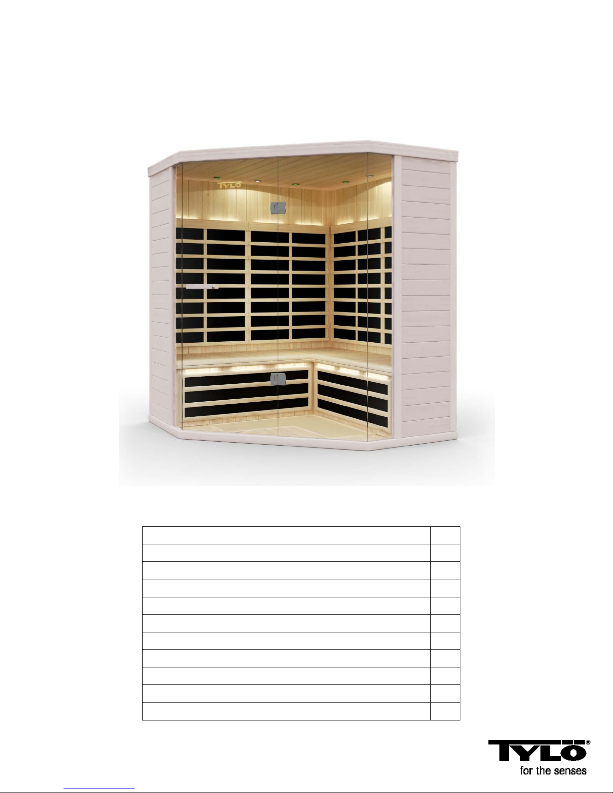
3 – 4 person infrared sauna
Precautions to be taken before commissioning
2
Pre-assembly information
2
Electrical requirements
2
Cabin construction/ assembly
3
Junction box connections
3
Main junction box connections
7
Power connections on the ceiling
9
Control panel instructions
12
Lighting: Internal/ external/ colour therapy
12
Maintenance & technical support
13
Wiring diagram
14
121210
Prime+ 1515/C
User Manual
Note: The cabin must be installed on a flat, level surface.
Page 1
Page 2

Precautions to be taken before commissioning Warning (space configuration and use):
• Correct electrical earthing is required
• Electrical sockets are not permitted in the sauna.
• Do not allow heating elements to come into contact with water.
• Do not fit a lock or bolt on the door.
• Do not block the ventilation holes.
• Children must always be supervised in the sauna.
• Clean the sauna with a damp cloth.
• Cleaning the sauna with steam cleaners, high pressure cleaners or spraying with water is not permitted.
Warning notice: Do not insert the sauna power cable into a socket before assembly is complete.
Warning (health restrictions):
• Being exposed to high temperatures for a long time may lead to hyperthermia (body temperature is several
degrees above 37° Celsius)
• Hyperthermia symptoms include: dizziness, lethargy, grogginess and feeling faint. Effects of hyperthermia:
o Failure to realise that you have to leave the infrared sauna.
o Damage to the foetus in pregnant women.
o Being physically unable to leave the sauna.
o Loss of consciousness
• Warning – the consumption of alcohol or drugs increases the risk of fatal hyperthermia.
• If you have health problems or are ill, consult your doctor before using the sauna.
• Stop using it immediately if you feel restless, if you start shaking, if you have a headache or feel sick
or nauseous.
• People who suffer from hyperthermia or cardiovascular diseases should seek medical advice before
using the infrared sauna.
• Do not use a sauna if you have drunk alcohol or taken tranquillisers or if you suffer from pain in the heat.
• Using the infrared sauna is not advisable if you have been exposed to UV radiation (a solarium or been
sunbathing) in the last 24 hours.
• Should you notice unusual skin changes after using the infrared sauna e.g. persistent erythema (reddening
of the skin for more than one day) or a reticular change in colour, you should stop using it and seek medical
advice.
Warning (fire risk):
• Do not use the sauna to dry clothing, bathing costumes etc.
• Do not hang towels or other objects on or in front of the infrared heat radiator.
• Never operate the infrared sauna with a damaged cable or a damaged socket.
Pre-assembly information:
a. Two (2) adults are required for assembling and installing the sauna.
b. Assembly tools: Phillips screwdriver
c. The boxes are labelled in order of assembly.
d. Note: The glass for assembling the front sauna panel is heavy and fragile.
Box
1: Floor, ceiling, long bench valance, short bench valance, fan component, manual,
Pack of 10 Phillips screws for the junction box covers
Box 2: Left and right wall panels
Long and short bench
Box 3: Left front, right front and front wall panel
Electrical requirements: The infrared sauna must have a 230 volt connection.
Page 2
Page 3
How to construct the sauna:
Note – there are (14) power connections inside the sauna.
(10) are in the sauna: left and right rear wall panels, left and right front, wall panels,
left and right bench valance, fan, left and right bench and main power connection
There are additional power connections on the top outer face of the ceiling.
(1) Mains connection cable for the sauna. Do NOT insert the main electrical connection
cable for the sauna into the socket before all the assembly steps have been
completed correctly.
------------------------------------------------------------------------------------------------------------------------------------------------
There are (8) power connection/ junction boxes that are labelled accordingly and must be connected after
assembling each section.
Left back wall panel Right back wall panel Left front Right front Left bench valance
B1 to B1 B2 to B2 L1 to L1 R1 to R1 S3 to S3
Right bench valance Left bench Right bench
S4 to S4 S1 to S1 S2 to S2
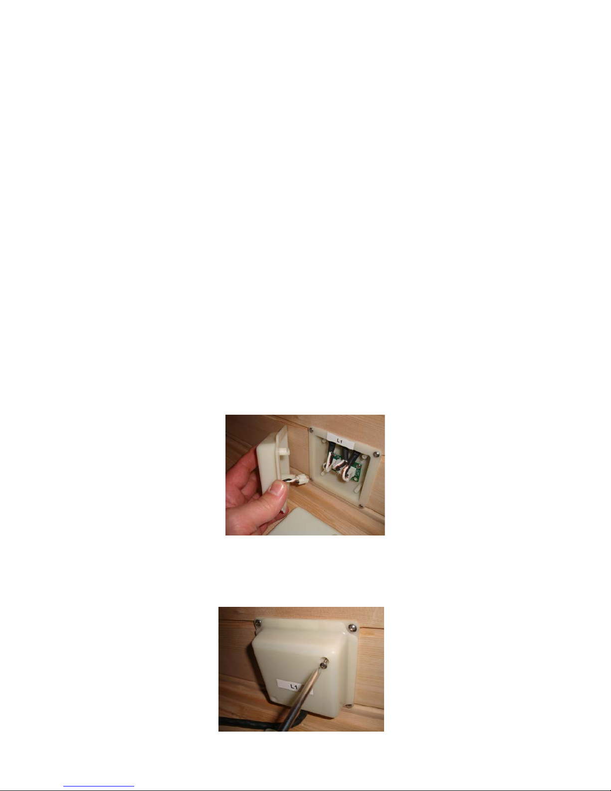
These (8) power plugs are connected easily by simply inserting the white plug of the white junction box
cover into the correct plug-in connection (3) in the junction box.
Example below: L1 to L1 (left wall panel power connection) (left wall panel junction box)
Fitting the junction box covers: After the junction box has been connected securely fix the junction box
cover with a Phillips screwdriver and 2 Phillips screws from Box 1.
Page 3
Page 4

Floor panel (Box 1): Put the floor panel on a level surface 8-16 cm from the wall panel and no more than
152 cm away from a 230V socket.
Position the floor panel in such a way that the slot for the glass sections are at the front of the sauna.
Note: Put the ceiling, bench valance and bench aside until the corresponding steps.
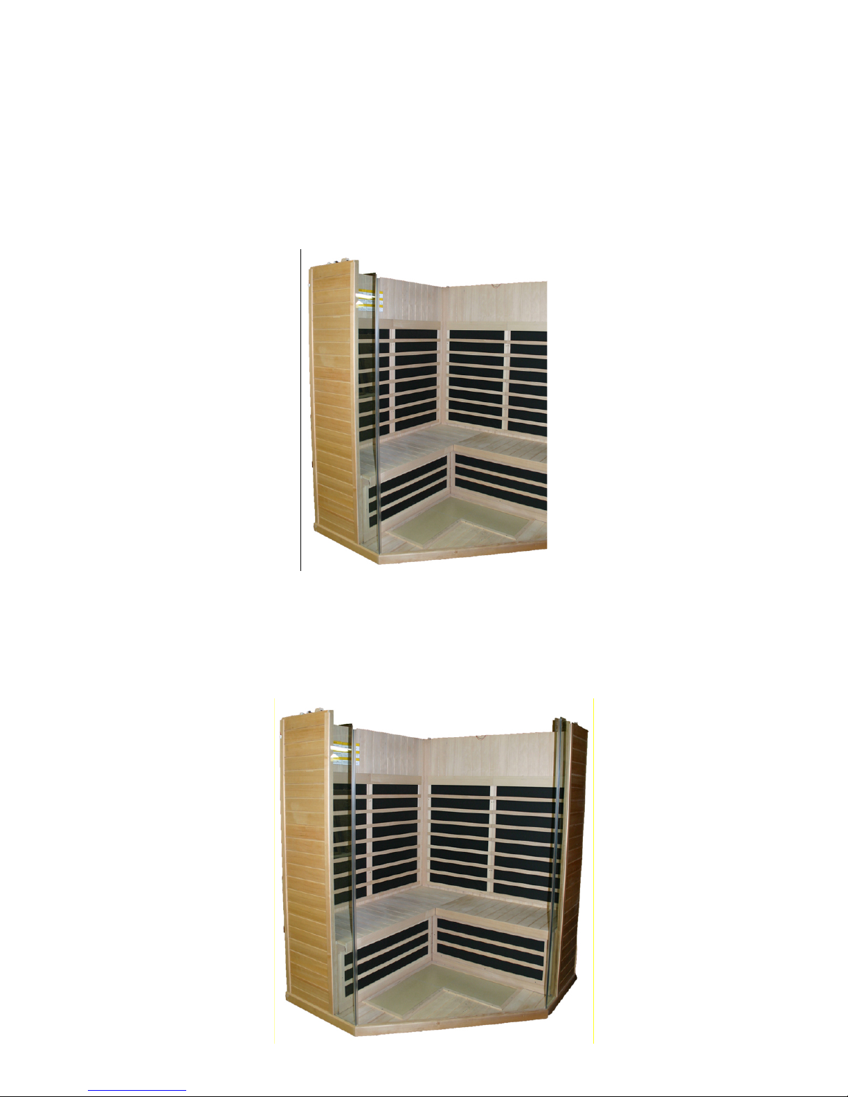
Left back wall panel and right back wall panel (Box 2):
• Place the left wall panel section into the back left hand slot of the floor panel.
• The back left rear panel section must be held in position while the right rear panel
section is located.
• Place the right wall panel section into the back right hand slot of the floor panel.
• Connect the right back panel section to the left back panel section.
o Lift the right back panel and push it onto the wall bracket.
• Connect the power connections to the B-1 junction box.
• Fix the cover of the B-1 junction box with 2 Phillips screws.
• Connect the power connections to the B-2 junction box.
• Fix the cover of the B-2 junction box with 2 Phillips screws.
Note – Put the benches aside until the Bench fitting section.
Page 4
Page 5
Left side wall panel (Box 3):
• Place the left wall panel section into the left hand slot on the floor panel.
• Attach the left wall panel to the back wall panel by lifting the left panel and pushing
it into the retaining bracket on the back panel.
• Connect the electrical supply to the B-1 junction box.
• Fix the cover of the L-1 junction box with 2 Phillips screws.
Note – Put the glass sections aside until the Front panel section.
Right side panel (Box 3):
• Place the right wall panel section into the right hand slot on the floor panel.
• Attach the right wall panel to the back wall panel by lifting the right panel and pushing
it into the retaining bracket on the back panel.
• Connect the R-1 electrical supply to the R-1 junction box.
• Fix the cover of the R-1 junction box with 2 Phillips screws.
Page 5
Page 6

Left bench valance (Box 1):
• Insert the bench valance between the left and right wall panel sections.
• Connect the S-3 electrical supply to the S-3 junction box.
• Fix the cover of the S-3 junction box with 2 Phillips screws.
Slide the fan component (Box 1) into the retaining bracket on the bench valance.
Connect the white connection of the black junction
box to the white connection on the fan.
Right bench valance (Box 1):
• Insert the bench valance between the left bench valance and the right side panel.
• Connect the S-4 electrical supply to the S-4 junction box.
• Fix the cover of the S4 junction box with 2 Phillips screws.
Page 6
Page 7

Black main junction box: Connections
Locate the black main junction box that is fixed to the internal floor of the sauna.
1 Insert the 24 pin, multicoloured cable plug into the left hand side of the main junction box.
See point 3 Input/output
2 The ON/ OFF switch is on the right hand side of the main junction box.
Set the switch as shown above to the ON (EIN) position.
3 Connect the loudspeaker input and output.
Note – Do NOT insert the 230 volt alternating current cable into the socket yet.
Long bench (Box 2):
• Rest the bench upright against the back wall panel.
• Connect the S-1 power supply to the S-1 junction box.
• Fix the cover of the S-1 junction box with 2 Phillips screws.
• Lay the bench down and push first the left hand and then the right hand edge into position.
• Push the seat onto the back wall panel.
Page 7
Page 8

Short bench (Box 2):
• Rest the bench upright against the back wall panel.
• Connect the S-2 electrical supply to the S-2 junction box.
• Fix the cover of the S-2 junction box with 2 Phillips screws.
• Lay the bench down and push first the right hand and then the left hand edge into position.
• Push the seat onto the back wall panel.
Front wall panel:
• Place the left hand glass section into the floor slot and the slot in the left hand wooden panel.
• Note: The long loop on the seal should be on the inside of the two fixed panels.
• Place the right hand glass section into the floor slot and the slot in the right hand wooden panel.
Page 8
Page 9

Ceiling:
• Lift the ceiling up and place it carefully on the five (5) panels as shown below.
• Note: Ensure that the (3) electrical connections – 1 on the front panel and 2 on the rear left panel –
are placed through the ceiling and are not disconnected when you put the ceiling into position slowly.
• Tip: To make it easier to pull cables through the ceiling slot, you can take small styropor blocks and
put them on several places between the ceiling and the panels so that the ceiling stays put in an
elevated position. When the cables have been pulled through, remove the styropor blocks and lower
the ceiling onto the panels.
• Lower the ceiling carefully onto the 4 wall panels.
Doors:
• Put the fixed right hand side section attached to the door into the floor slot provided.
• Align the door vertically to the ceiling edge until it touches the ceiling section.
• Lift the ceiling section up and place the fixed side section into the ceiling slot provided.
• Open the ceiling flap and turn the wooden locking device 90º in order to fix the glass sections.
In this way the side sections are firmly fixed to the ceiling. This ensures that the glass section
is firmly inserted into the door.
Page 9
Page 10

Ceiling to the rear panel: (4) connections:
Lift the door panel on the top left of the rear external face
of the ceiling. You will see 4 connections labelled 1–4.
Fix each ceiling connection 1–4 to the corresponding
number.
Ensure that they are connected securely to each other.
After connecting (4) close the ceiling flap.
Connection between the ceiling and front wall panel
• Lift the flap on the top of the ceiling.
You will see four connections.
• Note: Connect the two white ones to the black cables.
• Connect the other 2 connections matching the colours.
• Close the front ceiling flap.
A dipole radio antenna is supplied with your infrared sauna
for better FM reception.
You will find the dipole antenna in the bag in the installation manual.
1. Take the dipole antenna (black wires) out of the bag
in the installation manual.
2. Öpen the cover on the top of the ceiling above the touch screen.
3. Connect the dipole antenna to the wire marked 7
4. Spread the wire out and pull it apart to improve FM radio reception.
Page 10
Page 11

De luxe door handles:
Inside Outside
Your infrared sauna is now ready for use.
------------------------------------------------------------------------------------------------------------------------------------------------
Page 11
Page 12

Control panel instructions:
Main current: Press POWER to turn the sauna ON (AN) or OFF (AUS). If a red light comes on the sauna
is ON. If it is white the sauna is OFF.
Timer functions: Press and hold down or in order to set the running time. You can also run
your finger up or down the timer to set it.
Timer 2: Use this function with a pre-setting of up to 24 hours to set the sauna to come on later.
Temperature functions:
1. Press to switch between C and F. C or F will light up to show the required units.
2. Press and hold or to set the required temperature.
Pressing once will increase or reduce the setting in one degree intervals. You can also run your finger
over the temperature bar.
The central temperature display shows the actual sauna temperature.
3. Press to set the bench/ leg/ floor heat to ON or OFF. Red waves can be seen in heating mode
and white ones in OFF mode.
Light functions:
1. Press Inside light to switch it ON or OFF.
Note: Outside light ON or OFF will not work with S series models.
Colour therapy functions:
Press the colour therapy light in order to activate coloured light or a colour sequence. The sequence
is shown in detail below:
1. Press – RED
2. Press – RED-GREEN
3. Press – GREEN
Page 12
Page 13

4. Press – BLUE-GREEN
5. Press – BLUE
6. Press – BLUE-RED
7. Press – BLUE-RED-GREEN
8. Press – Activates the full rotation of all the 7 aforementioned colour therapies one after the other.
9. Press – Turns the colour therapy functions OFF.
Note: The colour of the light is indicated by the waves around the bulb symbol.
How to operate the radio and MP3 player
Press the radio icon to switch to radio mode.
Internal reception (only FM) varies. You can use USB,
micro SD or audio cable for MP3. You will have to use
an audio cable from your device for Apple products.
Loudspeakers are hidden sound generators. Some MP3
versions or other audio files can't be played back in the
USB or micro SD slot.
Troubleshooting tips:
a. Main control panel lights not lit up:
Check the electrical connections between the ceiling and the back wall panel and the front wall panel.
Ensure that the plug is correctly connected to the socket and the switch.
Ensure that the main switch (house) is not switched off (socket has power).
Ensure that the main control switch (under the bench) is not switched off and is ON.
b. The sauna does not heat up:
Ensure that the power cable is correctly inserted into the socket.
Ensure that all junction boxes are correctly connected under the bench as shown
in the junction box connection code in 4a.
Ensure that the main switch (house) is not switched off (socket has power).
Ensure that the main control switch (under the bench) is not switched off and is ON.
Ensure that the required temperature is higher than the actual sauna temperature.
(Control needs heat)
-------------------------------------------------------------------------------------------
Page 13
Page 14

Wiring Diagram
Page 14
 Loading...