

Page 1
Expression
130404
Art.nr 2900 6110
Page 2
WARNING!
(mm)
(mm)
kW
min./max
normal
"X"
recess
"Y"
10
10 - 18
200
200
100
1900
Output
Voltage
Amperage
Conductor
mm²
10
400V 3~
16
2,5
• Check before each use of the sauna that there are no foreign objects in
the sauna cabin, on or in the heater.
• Covering the heater can cause fire.
• Do not touch the upper parts of the heater - risk of burns!
• Incorrect ventilation or heater positioning can lead to the wooden
panelling drying out, causing a risk of fire under certain circumstances.
• The flooring in the sauna should be made of non-slip material.
• Never use a hose in the sauna.
• There should always be at least 50 mm of insulation directly behind the
wooden panelling in the sauna (no other materials such as chipboard,
plasterboard etc. may be used).
• The sauna door should open outwards, and should open easily with a
little light pressure.
• Do not use the sauna cabin for any purpose other than taking saunas.
• Do not install more than one sauna heater in a sauna cabin, unless you
follow special instructions for twin-heater installations.
• Fragrant essences and similar products can ignite if poured directly onto
the stones.
• Never leave small children unattended in the sauna.
• Saunas are not recommended for people in poor health. Please consult a
doctor.
• Please keep these instructions.
INSTALLATION
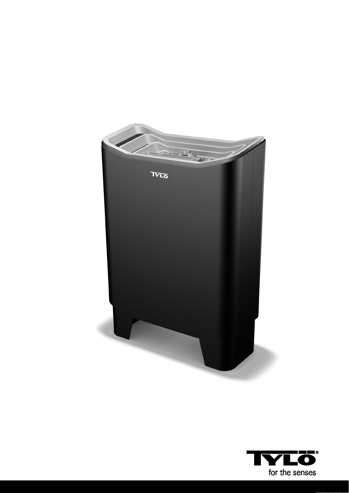
Fig. 1
Tylö Expression sauna heater with separate h1 control panel (CC10,
CC50, CC300, EC50, TS). Expression is designed for floor installation.
Assembly and installation of the sauna heater.
Fig. 2 - removing the outer casing
Push the front plate upwards. Lift off the outer casing to expose the
electrical wiring.
Fig. 3 - mounting the feet
Put the heater back in the lower part of the packaging. Attach the four
adjustable feet to the base.
Figs. 4, 5 - electrical wiring
Leave the heater in its packaging with the front facing upwards to
facilitate installation of electric cables. The packaging also protects the
back of the heater from scratching.
Undo the screws and open the cover.
After completing the electrical installation, replace the outer casing, fig.
7.
Position the heater on the same wall as the inlet vent, fig. 16.
distance from side wall: see table.
Volume and minimum distance:
Output Sauna
The Tylö sauna heater should be connected using standard wiring (Fk
or EKK), approved for fixed installation. Cables (EKK) or electrical
ducting must be run on the outside of the heat insulation, see figs. 12,
13, 14. Any single wires (Fk) must be protected by electrical ducting
(VP) up to the heater, or by internally insulated flexible metal tubing.
volume
. m³
Fig. 6 - silicone
To ensure that the heater is firmly installed, silicone should be applied
on the indicated installation surface (fig. 6) under the feet.
Fig. 8 - safety distance
A = normal installation. B = recess installation. Minimum distance from
side wall (X, Y): see table. Minimum distance from rear wall: 100 mm.
Min. distance from side
installation
wall (mm)
installation
Min.
distance
from
back wall
Minimum
Min.
ceiling
height in
sauna
When the Expression sauna heater is installed in a recess, the sensor
(C) should be positioned 250 mm from the rear wall and 300 mm from
the ceiling.
Fig. 9 - safety distance
Minimum distance between sauna fittings and the front of the sauna
heater.
Fig. 10 - sauna
(Expression sauna heater and CC/h1/EC50 control panel)
1 = sauna heater. 2 = thermistor (sensor). 3 = control panel CC 10/CC
50/CC 300/h1/EC50. 4 = external on/off switch (option). 5 = distribution
board. 6 = relay box RB30.
Wiring diagram, fig. 24
Fig. 11 - sauna
(Expression sauna heater and h1 control panel)
1 = sauna heater. 2 = thermistor (sensor). 3 = h1 control panel.
4 = external on/off switch (option). 5 = distribution board. 6 = relay box
RB30.
Wiring diagram, fig. 24.
Figs. 12, 13 - Expression + h1
A = electrical conduit. B = wooden panelling. C = insulation behind
control panel.
D = sensor. E = capillary tube/ thermistor wire. F = separate h1 control
panel. G = valve.
Figs. 13, 14 - Expression + CC/h1/EC50/TS
A = electrical conduit. B = wooden panelling. C = insulation behind
control panel.
D = sensor. E = capillary tube/ thermistor wire. F = separate control
panel CC/h1/EC50/TS. G = valve.
Amperage and conductor area:
kW
V
amp
area mm²
h1 control panel
User guide: supplied with control panel.
Manual and automatic on/off. Max. 24 hours connection time, 24 hours
preselected time.
The h1 control panel is controlled electronically with the option of
remote control from one or more locations. The wires between the
sauna heater and the control panel must be shielded (LiYCY). Connect
the shielding to terminal 12 in the control panel, see wiring diagram.
Alternative positions
Fig. 11. On the wall in the sauna cabin, max. 760 mm from the floor.
Fig. 10. Anywhere outside the sauna cabin.
EC50 control panels
User guide: supplied with control panel.
Installed at any distance from the sauna cabin.
EC50 panels are electronically controlled and available in the following
models:
EC 50-3. Manual and automatic on/off. Max. 3 hours connection time,
10 hours preselected time.
EC 50-12. Manual and automatic on/off. Max. 12 hours connection
time, 10 hours preselected time.
CC control panels
User guide: supplied with control panel.
Installed at any distance from the sauna cabin.
CC 50 panels are electronically controlled. Available in the following
models:
CC 10-3. Manual and automatic on/off. Max. 3 hours connection time,
10 hours preselected time.
CC 10-10. Manual and automatic on/off. Max. 10 hours connection
time, 10 hours preselected time.
CC 50-3. Manual and automatic on/off. Max. 3 hours connection time,
10 hours preselected time.
CC 50-12. Manual and automatic on/off. Max. 12 hours connection
time, 10 hours preselected time.
5
Page 3

CC 300. Built-in weekly time switch. Manual and automatic on/off.
Max. 24 hours connection time, 24 hours preselected time.
Fig. 24 - wiring diagram
1 = sauna heater. 2 = thermistor (sensor). 3 = control panel.
4 = external on/off switch (option). 5 = RB 30
Check the heater's data plate to ensure it is connected to the correct
voltage.
Don't forget - the installation must be earthed!
TS control panels
TS panels are thermally operated and have a patented divided output.
They should be mounted outside or inserted into the wall (fig. 14).
When inserted into the wall, there must always be insulation behind
the control panel. Capillary tube length 1850 mm. Also available with
capillary tube length 5000 mm.
Installation of sensor for TS control panel (fig. 17). A = capillary tube.
B = sensor holder. C = plastic capillary tube holder.
D = sensor for installation 300 mm from ceiling (fig. 14, not above the
sauna heater).
Extra equipment for TS control panel
Locking cover in transparent plastic to fit over the control panel.
Available with a design that prevents unauthorised changes being
made to the set time and/or temperature.
Fig. 27-29 - wiring diagrams
1 = sauna heater. 2 = control panel.
Check the heater's data plate to ensure it is connected to the
correct voltage.
Don't forget - the installation must be earthed!
Remote control
TS control panels use contactors for remote control operation.
Unusual voltages or numbers of phases
Before connecting to voltages or numbers of phases not listed in the
above wiring diagram, contact Tylö Customer Service.
Positioning of thermistor (sensor)
The thermistor should be positioned 300 mm from the ceiling on the
wall between the inlet and outlet vents (not above the sauna heater).
The thermistor wire can be extended beyond the sauna with a shielded
low voltage wire (2-core).
Tip: The thermometer should be placed at a height where the
temperature coincides with the exact numbers displayed on the h1.
NB: Seal any holes in the wall behind the thermistor.
Relay box (RB)
Installed outside and at any distance from the sauna. The relay box
must be positioned at a minimum distance of 1 metre from the h1.
Shielded low voltage wire (6-core).
The control cable from CC/h1/EC50 to the relay box must be a
shielded low voltage wire (6-core). Connect the shielding to terminal
12 in the control panel.
Lighting
Connect the lighting according to the wiring diagram.
Option: external switch
An external switch (optional) can be connected to the control panel.
See wiring diagram supplied with external switch (Item No. 9090
8045).
Impulse deactivation: The switch has an on/off function each time it is
pressed.
Constant deactivation: The panel continues running until switched off,
but never longer than the set running time.
When the heater is on, the indicator light in the external switch is
illuminated. If the panel is programmed for a later start, the indicator
light flashes.
6
BUILDING INSTRUCTIONS
It is important to install correct sauna ventilation.
Incorrect sauna ventilation can result in hot floors and benches and
scorched walls and ceiling (the temperature cut-out switch will be
triggered). Carefully follow the sauna ventilation instructions.
Set the adjustable outlet vent to evacuate 6-8 m³ of air per person per
hour when the sauna is heated.
Mechanical sauna ventilation can cause the wooden panelling to dry
out, resulting in a fire risk.
Fig. 15, 16 - the inlet vent should always be installed
directly underneath the sauna heater.
Position the inlet vent straight through the wall under the centreline of
the heater. Vent size for family sauna approx. 125 cm², for larger
sauna
approx. 300 cm².
Fig. 18 - the outlet vent must never lead
outdoors
The inlet and outlet vents must be the maximum possible distance
apart, e.g. positioned diagonally. The outlet vent must be positioned
high up on the wall or on the ceiling, and must have the same area as
the inlet vent.
The outlet vent should always vent into the space where the door and
inlet vent are positioned. It must never vent directly outdoors. The
outlet air from the sauna is constantly renewed in the room outside.
This thermal ventilation system works independently of any negative or
positive pressure in adjacent rooms.
Any cavity above the sauna ceiling should not be completely sealed.
Leave at least one vent hole on the same wall as the sauna door.
Option A: Outlet vent through sauna wall (seen from above). Position
the vent high up, near the ceiling.
Option B: Outlet vent through cavity above sauna ceiling (seen from
side).
Option C: Outlet vent via duct under ceiling inside sauna (seen from
side). Position the outlet air duct in the angle between the ceiling and
wall. The duct can be built out of wooden panels, and should have the
same area as the outlet vent.
Special information for steam sauna (Tylarium)
Do not position the outlet vent so that it leads to a part of the building
that is kept cold. This eliminates the risk of condensation.
Fig. 19 - recommendations for sauna construction
A. Floor frame, corner posts, vertical studs, ceiling frame.
B. Horizontal studs, ceiling studs, vents.
C. 50 mm mineral wool as heat insulation, approx. 20 mm air gap
between insulation and outer wall (if applicable).
D. 12 mm wooden panelling for walls and ceiling. There should always
be at least 50 mm of insulation directly behind the wooden
panelling in the sauna. No other materials such as chipboard,
plasterboard etc. may be used)
E. Bonded, non-slip plastic floor covering extending approx. 50 mm up
the walls behind the wooden panelling.
F. Inlet vents that should always be fully open may be fitted with a
slatted grille on the outside.
G. Outlet vent, can be fitted with a sliding hatch to adjust through-
flow.
H. Benches, minimum 22 mm in knot-free pine (alternatively
aspen, lime or obeche).
I. Drainage channel (should always be installed in public saunas).
Never position a drainage channel or drain beneath the sauna
heater.
Fig. 20 - heater guard
The stones and upper part of sauna heater are very hot! To avoid risk
of accidental contact, Tylö recommends that a heater guard always be
installed around the heater as shown in the drawings.
Page 4

Tip:
• There should never be a drain in a sauna. However, all public
saunas should have a drainage channel (I, fig. 19) connected to a
drain outside the sauna (private saunas do not need a drainage
channel).
• If the sauna has a window in the door or wall, treat the whole lower
moulding with spar varnish and seal the joint between the glass and
moulding with wet room silicone to prevent condensation on the
glass surfaces from leaking into the joint.
• Varnish the threshold and door handles with two coats of spar
varnish to maintain the wood's finish and make it easier to clean the
sauna. Sauna benches, decorative screens and back rests should
be oiled on both sides with Tylö sauna oil (this is particularly
important in the Tylarium).
NB: All other wood in the sauna should be untreated.
• Install floor decking only if the floor is slippery. Floor decking is
impractical and prolongs the drying time for any water spilt on the
floor.
• Coat the bucket and ladle with spar varnish, or oil them with Tylö
sauna oil. This will keep the bucket watertight and keep the wood
beautifully preserved. Never leave the wooden bucket in the sauna
after taking a sauna.
• Before using the sauna for the first time, heat the sauna cabin up to
approx. 90°C and leave the heater running for about 1 hour. This
will clear the "new” smell out of the sauna.
• Clean the sauna regularly. Scrub the benches and floor with soft
soap detergent, which is gentle and leaves a pleasant fragrance.
GENERAL INFORMATION
Fig. 21 - filling the stone compartment
Only use dolerite stones (Tylö sauna stones), as "ordinary" stones can
damage the unit. Fill the stone compartment around the heating
elements from the bottom to the top and approx. 50 mm above the
front top edge, without pressing the stones into place.
Fig. 22
Never place stones on top of the side air chambers. Covering the
vents will obstruct air circulation, the unit will overheat and the cut-out
switch will activate.
Check the stone compartment at least once a year.
This is especially important for public saunas and saunas in frequent
use. Instructions: Remove all the stones from the compartment. Clean
any small stones, gravel and limescale deposits from the bottom of the
stone compartment. Only replace whole, undamaged stones. Replace
damaged stones with new dolerite stones as required.
Temperature cut-out
Tylö sauna heaters have a built-in temperature cut-out device in the
terminal box at the bottom of the heater. It activates automatically if
there is any risk of overheating. If the cut-out has activated, it is usually
because of poor ventilation, incorrect heater location or an incorrectly
filled stone compartment. Contact an electrician to reset the cut-out
device.
Fig. 23
The ladle should always be used to sprinkle water on the stones,
never a hose or bucket. NB: The stones must be very hot.
A pleasant fragrance can be created by using fragrance essences.
Pour a few drops of the essence into the fragrance holder.
To maintain a comfortable basic level of humidity in the sauna, fill the
built-in air humidifier with water before switching on the sauna.
A. Fragrance holder
B. Air humidifier
Clean the fragrance holder and air humidifier as required. Remove
them and rinse them under running water.
Time setting on control panel TS 16-3(B), TS 30-03
and Expression sauna heater.
The first digits 1-2-3 indicate the connection time. The subsequent 9
digits indicate the preselected time.
For direct connection: Turn the dial past the first 3 and then back to
the required connection time (1, 2 or 3 hours).
The timer will stop automatically when it reaches 0.
Automatic connection: Turn the dial to 9, and then back to the
required preselected time (= the time the heater is to automatically
come on). The timer will stop automatically when it reaches 0.
You can turn the dial forwards or backwards at any time, e.g. to
manually stop the heater (turn to 0) or to change a previous setting.
Time setting on control panel TS 30-012
The digits 1-12 on the timer indicate the connection time. The sauna
heater is connected for the number of hours that the dial is set at, and
automatically switches off when it reaches 0.
You can change the time setting at any time, and you can manually
switch off the heater by turning the dial to 0.
GUIDELINES FOR USING THE
SAUNA
• Always have a shower before entering the sauna.
• Take a towel in with you to sit on. Stay inside the sauna only as long
as it feels pleasant. Go out now and then to cool off with a
refreshing shower.
• Show consideration for other sauna users. Don’t set the
temperature higher than is pleasant for everyone using the sauna.
• Young children love saunas. Let them splash around in a tub of
water on the floor or on the lower bench, where it is cooler. But
remember to keep an eye on them at all times.
• Round off your sauna with a long, cool shower.
• Never get dressed right after your sauna, or you will start perspiring
again. Relax without your clothes on outside the sauna. Have a cold
drink and enjoy the sensation of true well-being. Don’t get dressed
until your body has cooled down and your pores have closed.
You can enjoy traditional dry and wet saunas with
all Tylö sauna heaters.
Dry and wet saunas have long historic traditions. A sauna is best
enjoyed at temperatures between 70-90°C.
In dry saunas, where the stones are not sprinkled with water, the
relative humidity (RH) is only 5–10%.
In wet saunas, where water is ladled onto the hot stones, the relative
humidity rises steeply to RH 10-25%, and you can feel the heat waves
vibrating in the air and massaging your skin. A few drops of Tylö
Sauna Fragrance added to the water poured over the stones bring a
pleasant, invigorating sensation to the nose and airways. Try rounding
off your sauna by pouring a little extra water over the stones, to
produce a pleasant tingling sensation on your skin. Wet saunas are
the most popular way of taking a sauna, and are generally considered
the most traditional method.
Important! Use ordinary drinking water. Salt water or brackish water
will damage the heating elements. Never use a hose to spray water
onto or into the heater. Always use the ladle to sprinkle water onto the
stones. Devices that provide continuous water sprinkling may not be
used in the sauna.
USER GUIDE
Expression and TS
Setting the temperature
The digits indicate a rising temperature scale. Find the sauna
temperature that suits you best. Begin, for example, by turning the dial
to position 4. If you want the sauna to be hotter or cooler, adjust the
dial up or down until you
After this, you can always leave the temperature setting at this level.
find your ideal temperature (usually 70-80°C).
In the event of problems, please contact the retailer where you purchased
the equipment.
© This publication many not be reproduced, in part or in whole, without the written permission
of Tylö.
Tylö reserves the right to make changes to materials, construction and design.
7
Page 5

h1
CC 100
ON
CC
INFO
MENU
TEMP
OFF
LIGHT
EC50
TS
4
3
2
5
6
1
7
3
8
2
9
1
0
TIME
0
5
1
TS
2
4
3
TEMP
1
3
2
4
7
5
6
Max.
250 mm
8
SILICONE
A
X
Min.
100 mm
B
YY
C
Max.
1000 mm
9
A = min. 400mm
B = min. 200mm
A
20
mm
B
Min.
Page 6

300mm
50-150cm
50-150cm
300mm
3
2
10
2
4
6
1
Expression + CC/h1/EC50
3
5
Max
760
mm
4
5
6
1
11
A
Expression + h1
A
300
mm
Max
760
mm
D
300
mm
B
C
E
F
F
G
E
D
F
B
C
G
12
Expression + h1
1413
Expression + CC/h1/EC50/TS
Page 7

A
B
15 16
A
18
C
D
17
B
C
Page 8

A
B
C
A
D
G
A
B
F
E
A
Sauna
I
19
Alt A Alt B
Min 20 mm
A = min. 200 mm B = min. 400 mm
A
A
A
20
Max 400 mm
H
B
B
B
21
22
23
A
B
Page 9

400 - 415 - 440 V 3N~
1 = Expression 10
24
2 = thermistor (sensor)
3 = CC/h1/EC50
4 = external switch
5=RB30
5
3x1.5mm²
5xTAB
3 x 1.5 mm²
WARNING! THIS APPLIANCE MUST BE EARTHED!
25
6 x 0.2 mm²
1 = Expression 10
2 = thermistor (sensor)
3=
CC/h1/EC50
3
4 = external switch
5=RB30
3
4xTAB
3 x 1.5 mm²
5
3 x 1.5mm²
6 x 0.2 mm² (AWG 24) 2 x 0.5 mm² (AWG 20)
42
3 x 0.2 mm²
2 x 0.5 mm²
4xTAB
3 x 0.2 mm² (AWG 24)
7xTAB
53
11 12 13 14 15 16 11 12 13 14 15 16 17 18 19 20 21
5
40 41
200-240 V~
1.5 mm²
BB
NA
5
UZVXWY
BCD
142536
LLGL
123
1
L1 L2 L3 N
400-440 V 3N~
400 - 415 - 440 V 2N~
200-208-230-240V3~
53
11 12 13 14 15 16 11 12 13 14 15 16 17 18 19 20 21
42
G
LLL
123
1
200-240 V 3~
5
NABCD
UV ZXYW
12 4563
40 41
200-240 V~
5
BB
AB
AB
4*
2
1
1
G
WZ X Y
WZ X Y
UV
V
123456
23456
4* See wiring diagram delivered
with the External Switch
G
4*
2
1
WZ XY
UV
123456
G
WARNING! THIS APPLIANCE MUST BE EARTHED!
1 = Expression 10
26
2 = thermistor (sensor)
3=
CC/h1/EC50
4 = external switch
5=RB30
5
3 x 1.5mm²
3xTAB
3 x 1.5 mm²
WARNING! THIS APPLIANCE MUST BE EARTHED!
6 x 0.2 mm² (AWG 24) 2 x 0.5 mm² (AWG 20)
3
3 x 0.2 mm² (AWG 24)
7xTAB
1.5 mm²
200 - 208 - 230 - 240 V~
53
11 12 13 14 15 16 11 12 13 14 15 16 17 18 19 20 21
42
LLGL
123
1
200-240 V~
5
NABCD
UV ZXYW
12 4563
40 41
200-240 V~
1.5 mm²
5
BB
400-415-440V3~
AB
4* See wiring diagram delivered
with the External Switch
4*
2
1
WZ XY
UV
123456
4* See wiring diagram delivered
with the External Switch
G
1=
1=
1 = Expression 10
27
2 = TS 16-3
G
400-440 V 3~
WARNING! THIS APPLIANCE MUST BE EARTHED! WARNING! THIS APPLIANCE MUST BE EARTHED! WARNING! THIS APPLIANCE MUST BE EARTHED!
2
LULVLW
11
2233
1
Y6
X5
Z4
W3
V2
U1
G
28
400-440 V 3~
Expression 10
2 = TS 16-3 B
G
2
LULVL
N
2233
11
29
Y6
X5
Z4
W3
V2
U1
1
2
Max 500 W
2.5 mm²
G
G
400-440 V 3~
W
Expression 10
2 = TS 30-03, TS 30-012
22
LZULXVL
ABCD
141252363
YW
1
Y6
G
X5
Z4
W3
V2
U1
 Loading...