

Page 1
Installation and Operation Instructions
Black Line Series
16 CK
Wood Burning Sauna Stove
Installation and Operation Instructions
01/26/15
Rev. 2
Page 1
720-0101
R. D. LD
Page 2
Side walls:
Installation and Operation Instructions
Woodburning sauna stoves are regarded as fireplaces having scorching surfaces. In our stoves,
the surface temperature will not exceed 350 C, and the following safety distances should be
O
observed when using them:
Flammable structural elements such as wooden walls, sauna
seats etc.
20"
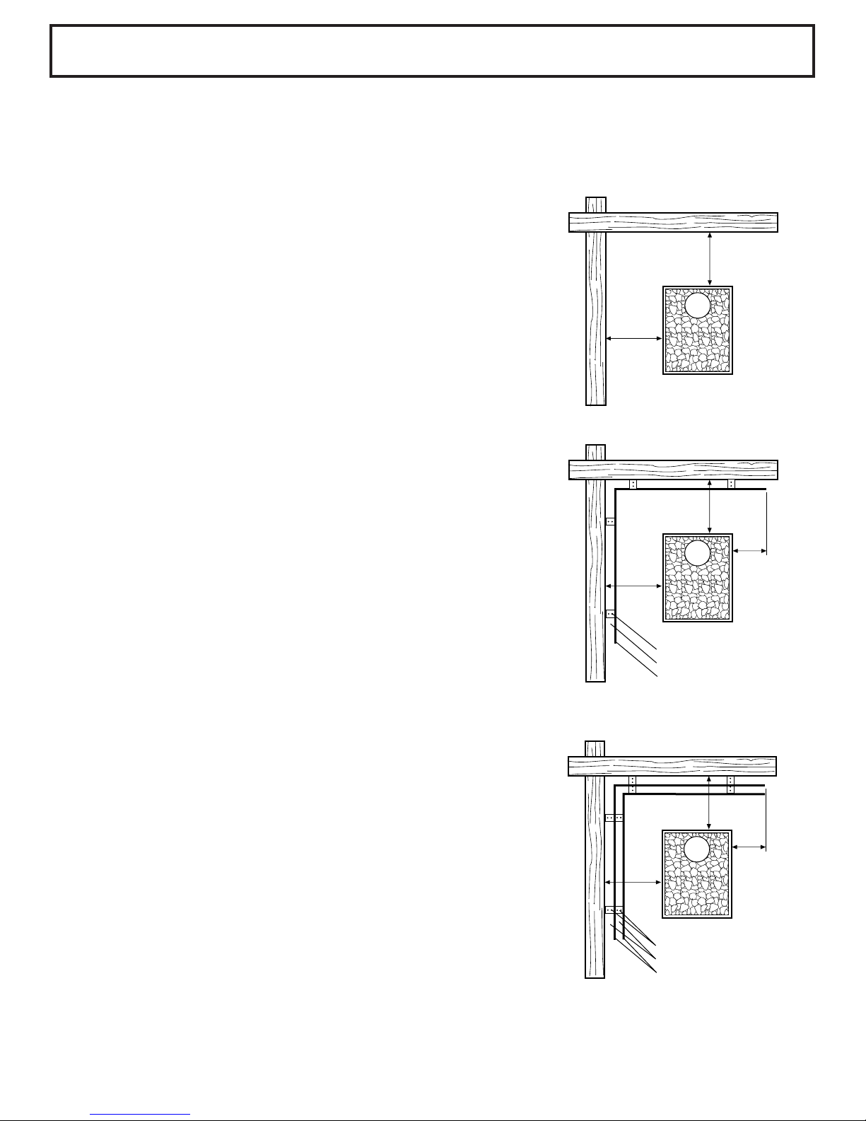
1. Minimum distance between the vertical surfaces of the stove
and any unprotected wooden structural element: 20".
(Figure 1)
Figure 1
20"
2. However, the safety distance mentioned in item
1 can be decreased to minimum 10" provided
a single light protection is used. This kind of single
light protection can be constructed either by using a
minimum 1/4" thick incombustible cement plate
reinforced with fiber, or by fastening an at least
10"
12"
1mm thick metal plate densely enough to the wall.
A minimum 1-1/4" vent hole must be left between
Figure 2
10"
the protective plate and the wooden surface to be
protected. This can be done for example by using
pipe bushings as intermediate supports.
(Figure 2)
Anchor screw
1-1/4" vent hole
.040" metal plate or 1-1/4"
thick incombustible cement
plate reinforced with fiber
3. The safety distance mentioned on item 1 can be
further decreased to minimum 5" provided a
double protection is used. The double protection
can be constructed using two plates described in
item 2, in addition to which an at least 1-1/4" vent
hole must be left between the wall and the plates.
(Figure 3)
01/26/15
Rev. 2
Page 2
Figure 3
5"
5"
Anchor screw
1-1/4" vent hole
.040" metal plate or 1-1/4"
thick incombustible cement
plate reinforced with fiber
12"
720-0101
R. D. LD
Page 3
Installation and Operation Instructions
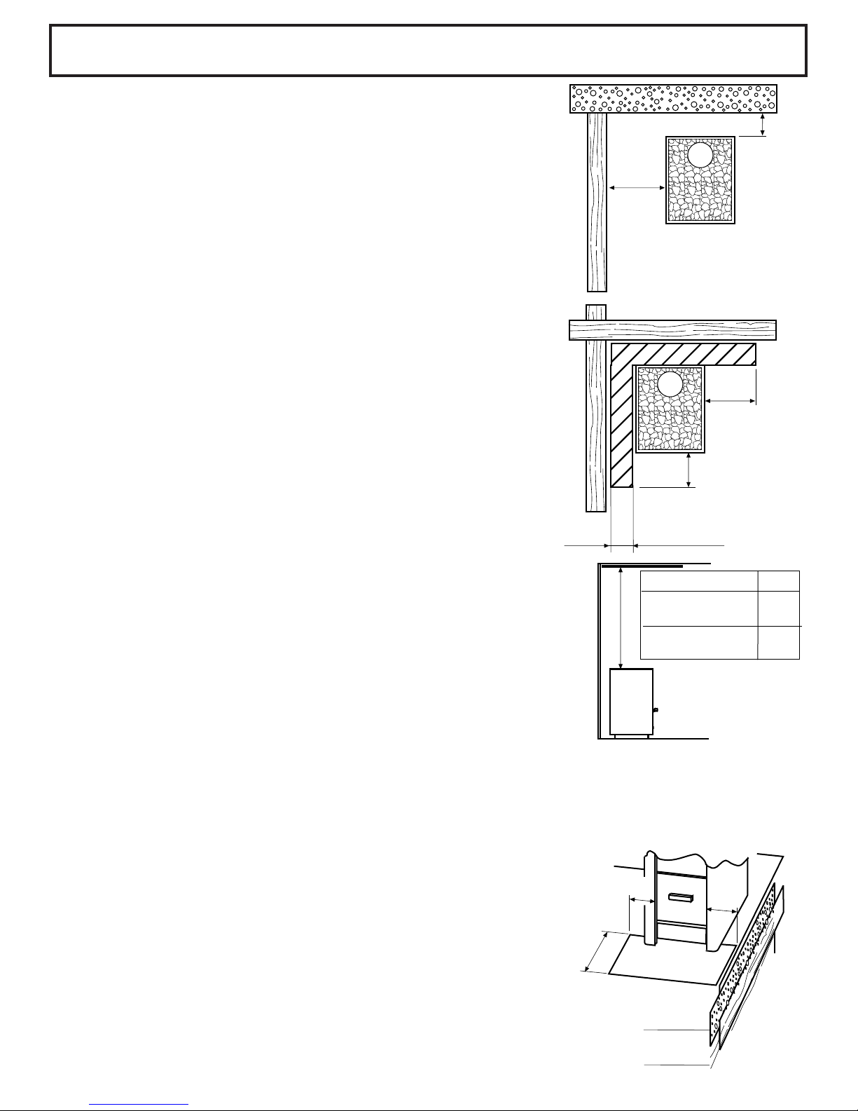
4. If the wall has been bedded in, a 2" vent hole
between the wall and the vertical surfaces of the
stove is enough. (Figure 4)
5. A 2-1/4" embedding with open sides at a minimum
1-1/4" distance away from the protected surface is
equivalent for a single light protection. Likewise,
a 4-1/4" embedding not touching the protected
surface would be equivalent for a double light
protection. (Figure 5)
Dimension A is determined according to the
protection method used for wooden surfaces
- 20" with no protection
- 10" with single light protection
- 5" with double light protection
Figure 4
Figure 5
2"
A
15-3/4"
Protecting the ceiling:
4-1/2"/ 2-1/4"
Provided the distance between the stove top and the
ceiling is minimum 47-3/4", no special protection is
needed for the ceiling. If the distance is less than 47-3/4",
you can choose one of the protection methods mentioned
in items 1-3. The ceiling protection must extend above the
vertical surfaces of the stove. (Figure 6)
Figure 6
F in
No protection for the 47-1/4
ceiling
F
Single light
protection
Fireplace base:
The fireplace must be installed on a rigid base. This base must be strong enough to bear the
weight of the fireplace and to prevent any excessive rise of temperature of the structural
elements connected to it. When installing the stove on a wooden floor, it is advisable to use a
minimum 2" thick concrete slab or a minimum 1/4" thick fiber-reinforced cement plate
covered by a metal plate.
Protecting the floor in front of the stove:
4"
Figure 7
4"
15-3/4"
35-1/2
The safety distances listed in items 1-5 cannot be applied
to a combustible floor area in front of the stove. This area
should be protected using a metal plate connected to the
floor and closely fitting the stove. The floor protection in
front of the stove must extend at least to 4" beyond
both sides of the oven mouth and to 15-3/4" in front of it.
01/26/15
Rev. 2
Page 3
15-3/4"
Concrete
Wood
720-0101
R. D. LD
Page 4

Installation and Operation Instructions
Wall protection and choices of materials:
If the wooden walls surrounding the heater are closer than the required minimum safety distance
recommends and the walls are made of a combustible material (panels, boards, logs, etc), the wall
surfaces must be protected.
A 2-3/16" masonry equals single-layer protection, and 4-3/8" masonry equals double layer protection.
The masonry must be open-ended and at least 1-18" from the surface being protected, extending 235/8" above the top of the heater, and have a 19-3/4" minimum safety distance on each side.
Wood materials used in the sauna room, such as panels, will darken over time. This darkening is caused
by temperature changes in the sauna. If the wall panels have been treated, the wall surfaces above the
heater will begin to darken very quickly depending on the treatment used. Darkening is due to the fact
that the treatment has a weaker resistance to heat than untreated wood. This has been proved in
material tests.
Fine-grained stone particles rising from crumbling sauna rocks with air currents may darken the wall
surfaces around the heater. If the heater installation instructions are followed, the heater will not heat up
combustible materials used in the sauna room to a dangerous level. The maximum allowed temperature
for wall and ceiling surfaces is +140 °C. Note! Glass and stone surfaces can be very hot to the
touch.
Installing the stove:
Install stove so the base rests firmly on a solid surface
and maintaining proper safety distances. The stove has
an opening in the top of the heater for the flu. Insert the
building pipe inside the pipe on the top of the stove.
Preheating:
In the factory, the interior parts of the stove have been coated with protective agents to prevent
corrosion during storage. Before starting to use the stove and placing rocks on the stove, you should
preheat the stove in order to remove these protective agents. A minimum of 3 oven fills of wood should
be burned for preheating. During preheating, sufficient ventilation should be arranged in the washroom
to dissipate the smoke gases produced by the protective agents.
01/26/15
Rev. 2
Page 4
720-0101
R. D. LD
Page 5

Installation and Operation Instructions
Stove rocks:
Always use rocks supplied by the manufacturer in your stove.
Before placing the rocks onto the stove, carefully wash them with clean water. Do not use any
detergents.
Place the rocks on top of each other so that they are level with the edge of the rock well. Be
careful not to place the rocks too close to each other to allow air circulation between the rocks.
Place the largest rocks at the bottom of the rock well.
Heating up the stove:
Only wood can be used for heating up the stove. Before heating, the stove grate should always
be cleaned and the ash pan emptied
Avoid heating the stove so that the passage in the rock well remains red heated for a long time
because this would overload the firebox and shorten the lifetime of the stove.
After your saunabath, you can leave a small fire in the stove to dry up the washroom constructions.
Stove maintenance:
The stove must be cleaned through the soot hatches at least once a year in order to maintain optimal
draft. At the same time, it is also useful to check the condition of the stove rocks and to replace
the decayed ones with new ones.
The wood burning stoves are manufactured and sold by: TyloHelo Inc.
01/26/15
Rev. 2
Page 5
720-0101
R. D. LD
Page 6

Installation and Operation Instructions
1
C
A
B
Heater
A. Hold on to the door. Push the hinge pin from the inside through
the console and through the upper hole of the door.
B. Push the hinge pin inwards.
C. Push the hinge pin through the console and the lower hole of
the door.
Changing the direction of the door opening:
01/26/15
Rev. 2
B
A
C
Heater
1
Page 6
1. Remove the ash box door.
A. Hold on to the door and lift the hinge pin upwards to enable
the lower part to come free from the holes of the door.
B. Pull outwards.
C. Pull down.
720-0101
R. D. LD
Page 7

Installation and Operation Instructions
Connecting to the chimney:
Check the fire safety of the chimney connection seal (use mineral wool or
ceramic fibre, if necessary).
Do not mount the light-duty flue to the heater. Attach the light-duty flue to
sauna structures only.
Ensure that the connecting flue duct diameter is correct and the joint is tight.
Other fireplaces on the same chimney:
Install one fireplace per chimney. Check fireplace function.
First heating: burning and other smells:
The first heating should be done in the sauna without rocks with the heater
connected to the chimney. The sauna must be thoroughly ventilated, and the
heater must be heated for an adequate length of time (min. 3 loads of firewood).
If the first heating is done outdoors, a minimum of 2-metre (6 ½) metal duct must be
used as a flue duct.
Sauna rocks, care and quality:
Use Saunatec-approved, prewashed rocks specifically intended for use in a
sauna heater (no ceramic).
Reload, and, depending on the frequency of use, replace sauna rocks at least
once a year.
Troubleshooting:
Stones that do not heat up:
Check the seal on chimney structures.
Reduce the draft.
Cleaning hatch is leaking.
Side panels and rear parts are overheating:
Check the seals on chimney and flue duct structures.
Overheating can shorten the useful service life of the chamber.
Ash drawer:
Empty the ash drawer regularly before each use.
01/26/15
Rev. 2
Page 7
720-0101
R. D. LD
Page 8

Installation and Operation Instructions
Sauna steam water:
We recommend the use of clean, fresh tap water.
Winter storage:
If the heater will be kept in the cold for the winter, remove all heater stones and clean out the
stone tray. Empty the ash drawer.
Fire safety instructions:
Before installation, check with your local fire safety authority on the most recent fire safety
regulations in force.
For technical assistance or service questions call 1-888-780-4427 and ask for Technical
Support. Prior to calling please have your model or type number of your stove. You can also
email us at: techsupport@tyloheloinc.com
01/26/15
Rev. 2
Page 8
720-0101
R. D. LD
 Loading...