

Tyloheloinc 4.5B Installation Manual
INSTALLATION AND OPERATING INSTRUCTIONS
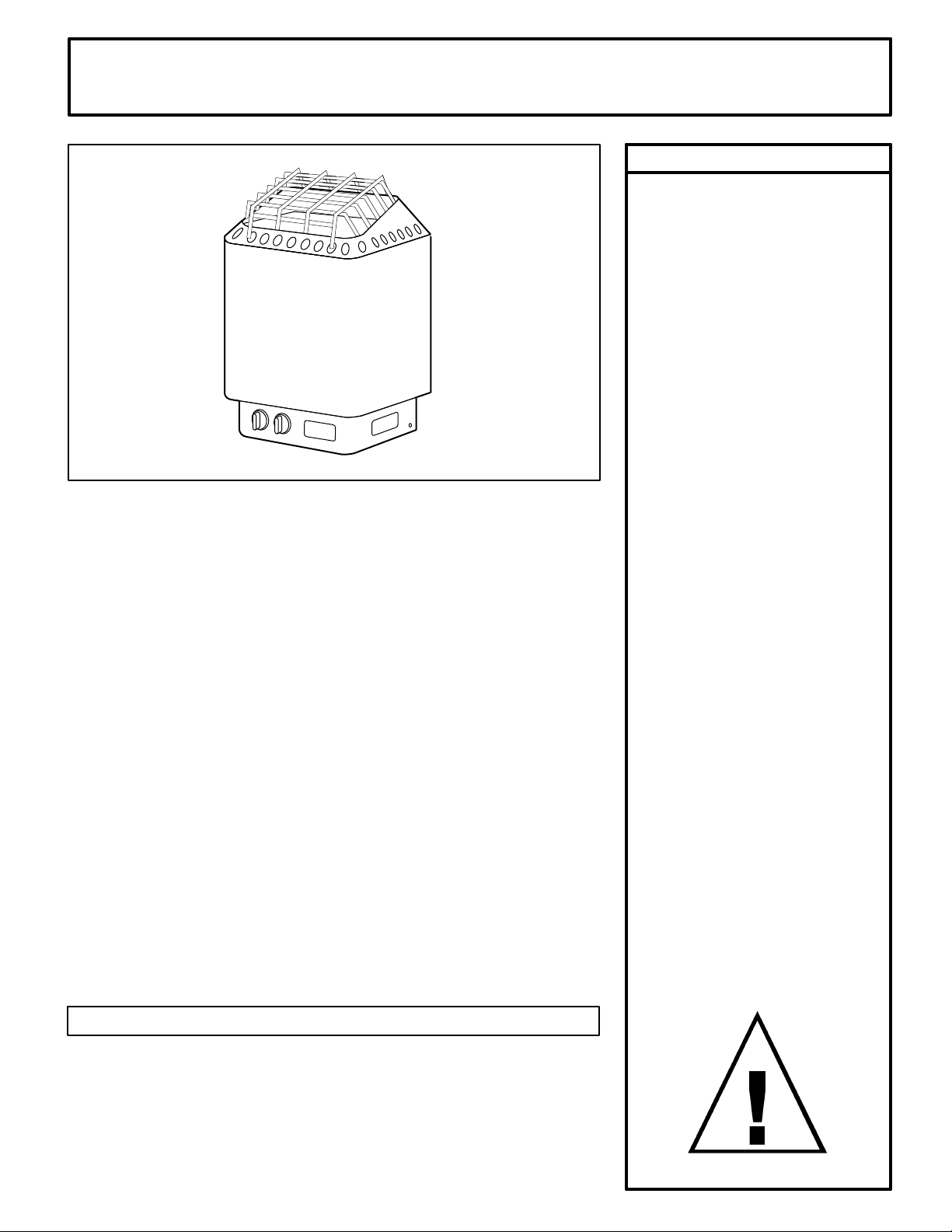
"DESIGNER B" SERIES SAUNA HEATERS
MODELS 4.5B, 6.0B, 8.0B (With built-in control)
(Model #'s 1712-45-17,1712-60-17,1712-80-17)
Read all instructions carefully before installation. Please leave all
instructions and warranty with the owner.
WARNING
Prolonged exposure to elevated temperatures is capable of inducing
hyperthermia. Hyperthermia occurs when the internal temperature of the
body reaches several degrees above the normal body temperature of
98.6°F. The symptoms of hyperthermia include an increase in the normal
temperature of the body, dizziness, lethargy, drowsiness, and fainting. The
effects of the hyperthermia include failure to perceive heat, failure to
recognize the need to exit the room, unawareness of impending hazard,
fetal damage in pregnant women, physical inability to exit the room and
unconsciousness.
WARNING
The use of alcohol, drugs, or medication is capable of greatly increasing
the risk of fatal hyperthermia.
Page 1
WARNING
Do not take a sauna if using
alcohol, drugs or medications.
Pregnant women or persons
with poor health should
consult their physician before
using any sauna.
Caution re hazard: Do not use
the sauna room for drying
clothes, bathing suits, etc. Do
not hang towels above heater
or place any object other than
the rocks supplied on the
heater. If any darkening of the
wall around the heater is
noticed discontinue sauna use
immediately.
Inspect sauna regularly for
required maintenance to
heater, control and benches.
Replace wood surfaces which
show any signs of
deterioration.
The heater gets extremely hot
during operation and should
not be touched or burns may
result.
Minors should be adequately
supervised whenever near a
hot or warming sauna.
SECTION 1: GENERAL INFORMATION
These heaters are ETL approved by Intertek for permanent installations and
electrical connections. Built with splash proof construction, the conducting
parts are protected against water. All wiring must be performed in
accordance with local codes. See Diagram 5 for wire and room size
requirements.
421 1-81 01 -20-20 20 701 4000 31 4 SKSM 103 J
INSTALLATION AND OPERATING INSTRUCTIONS
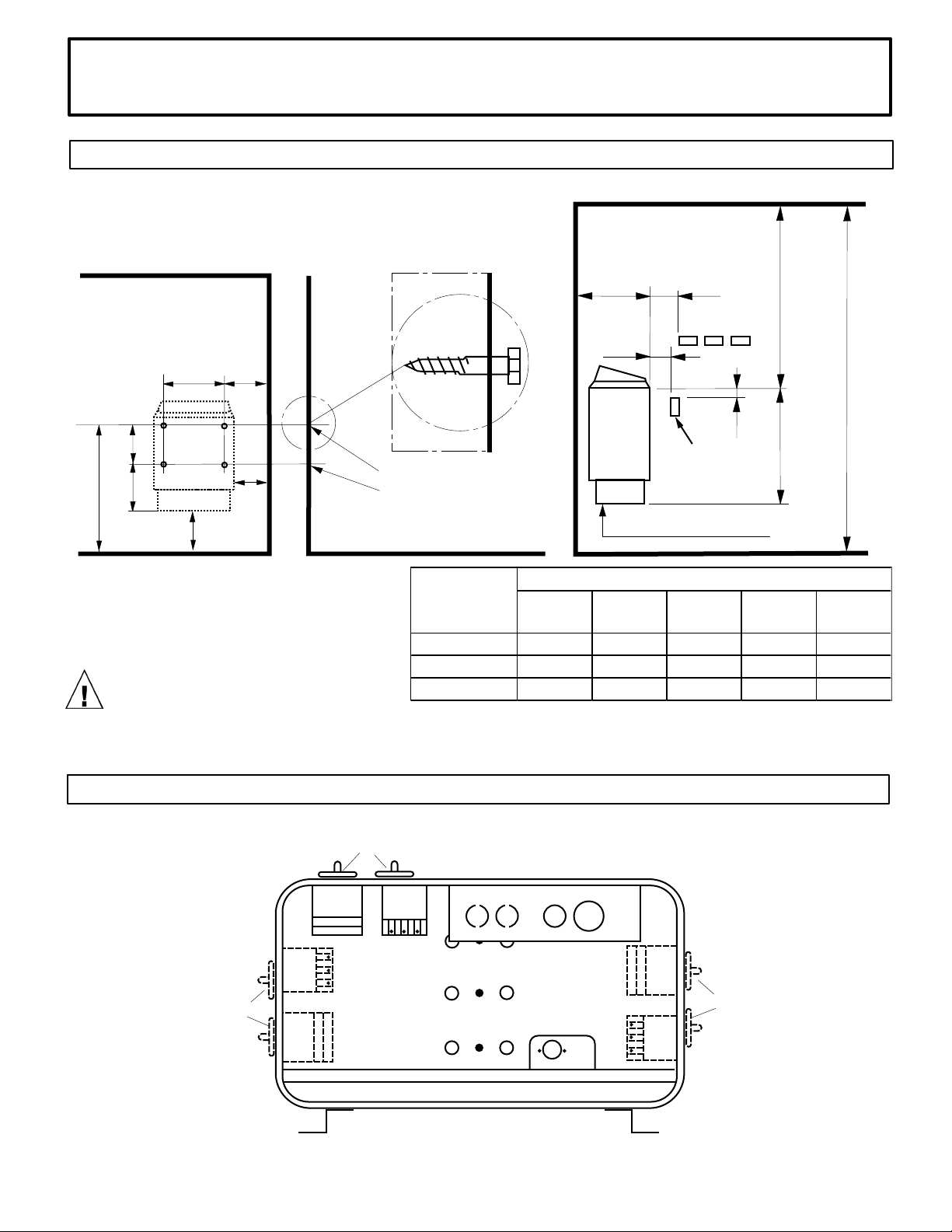
"A"
DISTANCE
"B"
DISTANCE
"C"
DISTANCE
"D"
DISTANCE
"K"
DISTANCE
DESIGNER 4.5B 3.0" 3 5/8" 4.0" 10 3/4" 23"
DESIGNER 6.0B
4.0" 4 5/8" 5.0" 10 3/4"
23"
DESIGNER 8.0B
5.0" 5 5/8" 6.0" 11 1/2"
23"
HEATER
MINIMUM
DIAGRAM 1
MOUNTING BRACKET LOCATION AND TO MINIMUM DISTANCE TO COMBUSTIBLE MATERIAL
All wiring for sauna system or accessories should be routed inside the
walls or away from the high temperature air from the sauna heater.
Page 2
14 3/8"
B
6"
K
10½"
6½"
A
Min.
Recheck your distances from the
heater to combustible materials to
be sure you have the proper
minimum distances.
OBSERVING MINIMUM DISTANCES IS
REQUIRED TO REDUCE FIRE HAZARD
CAUTION: Avoid re, Do Not Place Combustible Material on sauna heater / ATTENTION:
Evitez les Incedies, Ne Placez Aucne Matiere Combustible Sur Lle Chauffe-saun
Screws
Use the long screws in the upper
holes of the mounting bracket
D
C
(Upper Bench)
2"
Guard
Rail
High Limit Control
44"
Minimum
74"
Minimum
1"
18½"
DIAGRAM 2
4
2 1
1
4
Left
side
Alternate
Location
1. Timer
421 1-81 01 -20-20 20 701 4000 31 4 SKSM 103 J
2. Thermostat
2
3. High limit control (Reset)
4. Knobs for the thermostat and the timer.
Front
Back
2
4
Right
3
1
side
Alternate
Location
INSTALLATION AND OPERATING INSTRUCTIONS
Page 3
SECTION 2: MOUNTING OF SAUNA HEATER
For ease of operation, the heater controls may be mounted on the front or
either side. If the controls are relocated, this should be done before
mounting the heater to the wall.
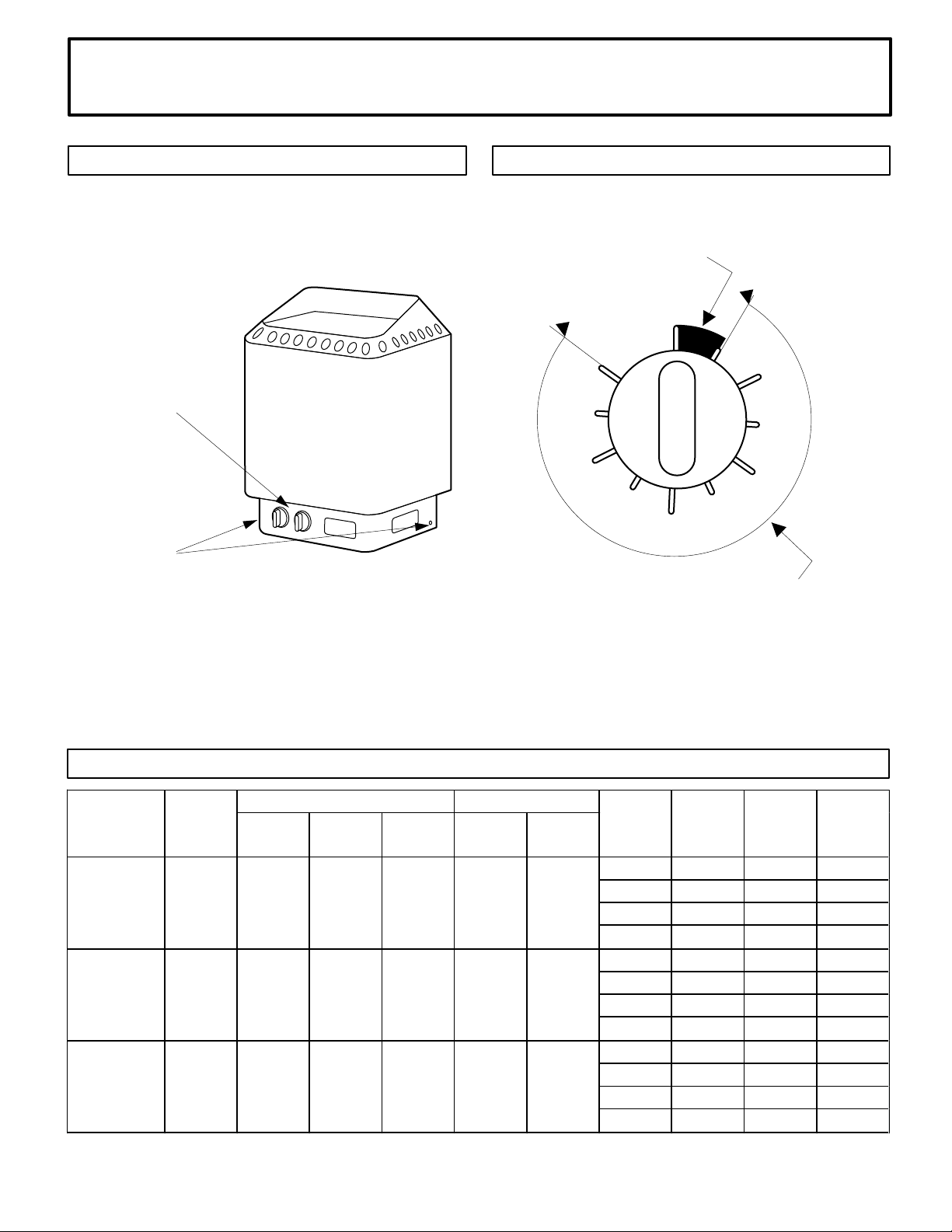
MOVING THE CONTROLS Lay the heater on its back: remove the control
knobs by pulling them straight off (See Item 1 on Diagram 3); unsnap the
plastic label plates from the left and right sides of the electrical enclosure
and remove the screws from the left and right sides of the electrical box
(See Item 2 on Diagram 3) and from the bottom cover of the box. Remove
the painted trim piece from the front of the box. Remove the bottom cover
by sliding it towards the back of the heater.
Remove the screws mounting the controls then carefully move the controls
to their new position. Reassemble in the reverse order using the original
hardware. Ensure that no wires are pulled loose, pinched, kinked, pulled
tight or otherwise damaged. Use the plastic label plates to cover the
unused control mounting positions.
HANGING THE HEATER Using the template provided, drill four 9/64" holes
to fasten the heater to the wall. Install two ¼" x 1 ½" hex head lag screws
(supplied with the heater) into the upper two holes. Tighten these screws
until their heads are about 1/8" from the wall surface. The screws must be
threaded through the wall into a framing member or backing board to
support the heater weight. Hang the heater on the two upper screws.
Locate the two ¼" x 1" hex head lag screws (supplied with the heater) then
install them into the two lower mounting holes. Tighten to lock the heater in
place.
WARNING
Fire sprinkler systems used
inside any sauna room should
be properly rated for sauna
room temperatures.
Do not pour chlorinated pool or
spa water on heater. Excessive
water use on heater may cause
damage and void warranty.
Electric Shock Hazard - High
voltage exists within this
equipment. There are no user
serviceable parts in this
equipment. All installation and
service to this equipment
should be performed by
qualied licensed personnel in
accordance with local and
national codes.
Do not construct sauna room
so as to restrict air ow through
the bottom of the heater.
Packing the rocks too tightly
may cause the heater high limit
switch to trip.
See Diagram 1 & 2 for the heater location details and the necessary
clearances to combustible materials.
SECTION 3: PLACING OF ROCKS (SEE DIAGRAM #10)
The rocks supplied with the heater have been chosen to provide the best
heater performance. Use of any other type of rock may void the heaters
warranty. Never operate the heater without rocks in place!
Rinse the rocks with water before placing in the heater. Carefully place the
rocks loosely so that the air can circulate through the heater. Packing the
rocks too tightly may cause the heater high limit switch to trip. The rocks
must fully cover the heating elements. Attach the guard with the screws
provided.
421 1-81 01 -20-20 20 701 4000 31 4 SKSM 103 J
INSTALLATION AND OPERATING INSTRUCTIONS
Floor Area
Wall
Height
Volume
Cu.Ft.
Wall
Height
Volume
Cu.Ft.
1 208 21.6 10-2 W/G
1 240 18.8 10-2 W/G
3 208 12.5 12-3 W/G
3 240 10.8 12-3 W/G
1 208 28.8 8-2 W/G
1 240 25 10-2 W/G
3 208 16.7 12-3 W/G
3 240 14.4 12-3 W/G
1 208 38.5 8-2 W/G
1 240 33.3 8-2 W/G
3 208 22.2 10-3 W/G
3 240 19.2 10-3 W/G
HEATER
MODEL /
Product Number
KW
MINIMUM ROOM
MAXIMUM ROOM
PHASE
VAC
DESIGNER 4.5B
(-3 = 3 Phase)
1712-45-17
4.5
12 sq. ft.
74"
100
96"
AMPS
WIRE SIZE
210
DESIGNER 8.0B
(-3 = 3 Phase)
1712-80-17
8
31 sq. ft.
74"
310
DESIGNER 6.0B
(-3 = 3 Phase)
1712-60-17
6
21 sq. ft.
74"
175
96"
250
96"
425
Page 4
DIAGRAM 3
MOVING THE CONTROLS
1.
2.
1. Remove knobs.
2. Remove screws on side of heater.
DIAGRAM 4
ONE HOUR OPERATING ZONE FOR 9 HOUR DELAY TIMER
This area from "OFF" to "ON" is the operating zone. This is
the only time the heater is on.
OFF
ON
9
1
8
2
7
3
6
5
DELAY ZONE
This area from "9" to "ON" is the delay zone, meaning the
heater can be programmed to come on up to nine hours
later. The heater will not operate in this area.
4
421 1-81 01 -20-20 20 701 4000 31 4 SKSM 103 J
DIAGRAM 5
 Loading...