

Tylo Air 10 Installation Manual
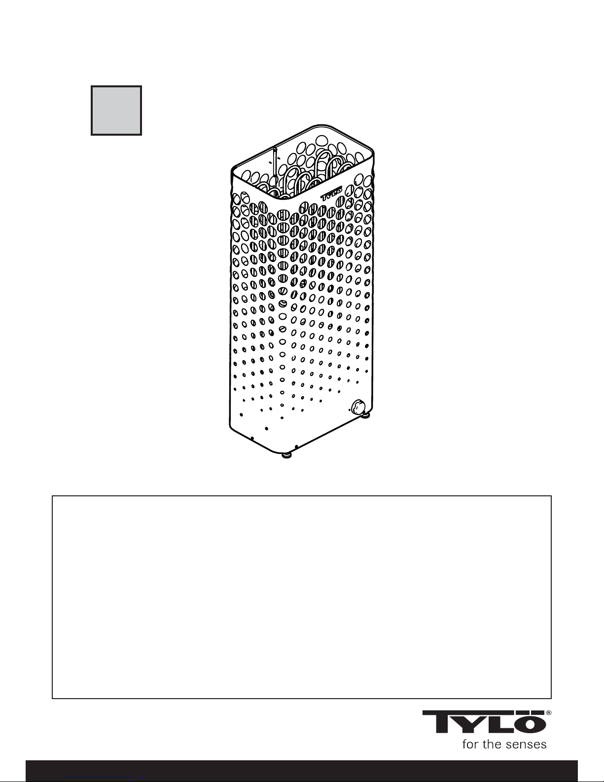
TYLÖ AIR
1604
2900 5230
SVENSKA
INSTALLATIONSANVISNING
ENGLISH
INSTALLATION GUIDE
DEUTSCH
INSTALLATIONSANLEITUNG
FRANÇAIS
NOTICE D’INSTALLATION
РУССКИЙ
ИНСТРУКЦИИ ПО УСТАНОВКЕ
POLSKI
INSTRUKCJA INSTALACJI
NEDERLANDS
INSTALLATIEHANDLEIDING
A
7
PRIOR TO INSTALLATION
Parts
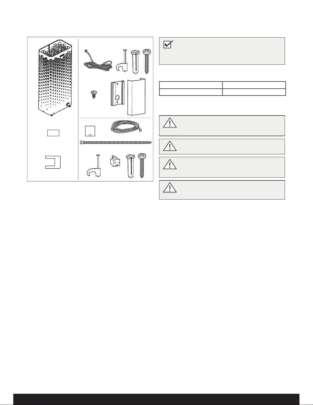
Check that the following parts are included in the packaging:
Figure 1: Sauna heater/control panel parts
1. Sauna heater
2. Warning label in ten languages
3. Connectors x 3 pieces
4. NTC Sensor, cable length 4 m
5. Clips TC (3-5) x 10 pieces
6. Plastic plugs 25x5 x 2 pieces
7. Screws RXS/A2 PHIL B6x25 x 2 pieces
8. Screw B4x6,5 x 1 piece
9. Sensor cover
10. Control panel
11. Cable between the heater and the control panel, RJ10 4P4C,
cable length 1 piece x 5 m
12. Cable tie
13. Clips C3x5 x 10 pieces
14. Modular plug 4, 4/4RJ10 x 2 pieces
15. Plastic plugs 25x5 x 3 pieces
16. Screws RXS/A2 PHIL B6x25 x 3 pieces
Contact your dealer if any parts are missing.
The Pure control panel comes with Tylö Air, see separate guide.
Installation requirements
To ensure safe use of the heater, check that the following criteria
are met:
• Cable (EKK) or electrical ducting for connecting the heater
must be run on the outside of the heat insulation.
• The cables must be run correctly (see the Connection/wiring
diagram section, page 11).
• The fuse size (A) and the power cable size (mm²) must be
suitable for the heater (see the Connection/wiring diagram
section, page 11).
• The sauna ventilation must comply with the instructions in
this manual (see the Air intake valve positioning section,
page 9, the Air exhaust valve positioning section, page 9).
• The position of the sauna heater, control panel and sensors
must comply with the instructions in this manual.
Installation tools
The following tools and materials are needed for installation and
connection:
• water level,
• adjustable spanner,
• screwdrivers.
Installation planning
Before starting to install your sauna heater, you should:
• Plan the sauna heater positioning (see the Heater positioning
- normal installation section, page 8).
• Plan the control panel positioning (see the attached
instructions for the control panel for allowable positioning).
• Plan the sensor positioning (see Figure 3, page 8 and
Figure 5, page 8).
• Position the air intake vent (see the Air intake vent positioning
section, page 9).
• Position the air exhaust vent (see the Air exhaust vent
positioning section, page 9).
• Plan the electrical installation (see the Connection/wiring
diagram section, page 11).
NOTE! A brick wall without heat insulation increases
the warm-up time. Each square meter of plastered
ceiling or wall surface equals an additional 1.2–2 m³
of sauna volume.
1
4
3
13
2
8
9
11
12
10
14
15
5
16
6
7
DANGER! Poor ventilation or heater positioning
may lead to dry distillation, posing a fi re risk
under certain circumstances!
DANGER! Insuffi cient insulation of the sauna
cabin may pose a fi re risk!
DANGER! Use of the wrong materials in the
sauna cabin, such as particle board, drywall, etc.,
may pose a fi re risk!
DANGER! The heater must be connected by
a qualifi ed electrician pursuant to applicable
regulations!
Table 1: Output and sauna volume
Output kW Sauna volume min./max. m³
10.5 10-18
• The heater's output (kW) must be adapted to the sauna's
volume (m³) (see Table 1). The minimum and maximum
volumes must not be exceeded.
8
Positioning the heater - recess installation
To position the sauna heater in a recess:
1. Position the heater at a safe distance from the fl oor, side
walls and interior fi ttings (see Figure 5).
2. Position the sensor according the picture (see Figure 5).
2
3
1
45
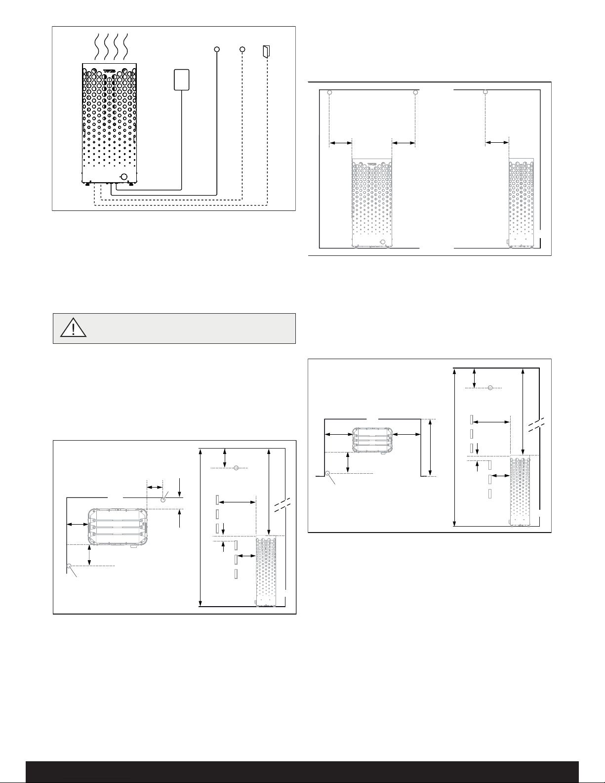
Figure 2: Schematic diagram of installation
1. Sauna heater
2. Control panel
3. Sensor
4. External on/off switch (option, door contact needed for function)
5. Door contact (option)
Positioning the heater - normal installation
DANGER! No more than one heater may be
installed in the same sauna cabin.
Position the sauna heater:
• on the same wall as the door (or the side wall, if very close
to the door wall). The heater may also be placed in a recess
(see Figure 5).
• Position the heater at a safe distance from the fl oor, side
walls and interior fi ttings (see Figure 3).
Position the sensor according the picture (see Figure 3).
If the wall on which the sensor is to be installed is made of highly
heat-absorbing material (e.g. concrete, brick, etc.), or of hardened
glass, the sensor may be installed in the ceiling at a distance from
the heater, according to Figure 4.
1
4
8
11
10
2
6
5
9
7
3
3
Figure 3: Positioning the heater - normal installation
1. Minimum distance from the side wall: 120 mm
2. Sensor position alt 1: 700 mm from the heater
3. Sensor
4. Minimum distance from the back wall: 120 mm
5. Sensor position alt 2: 700 mm from the front of the heater
6. Sensor position: 200 mm from the ceiling
7. Minimum distance to the ceiling: 970 mm
8. Minimum distance to interior fi ttings: 120 mm
9. Minimum ceiling height: 1,900 mm
10. Minimum distance: 20 mm
11. Minimum distance to interior fi ttings: 120 mm
Figure 5: Positioning the heater - recess installation
1. Minimum distance to the side wall: 120 mm
2. Sensor
3. Max. 1,000 mm
4. Sensor position: 700 mm from the front of the heater
5. Sensor position: 200 mm from the ceiling
6. Minimum distance to the ceiling: 970 mm
7. Minimum distance to interior fi ttings: 120 mm
8. Minimum ceiling height: 1,900 mm
9. Minimum distance: 20 mm
10. Minimum distance to interior fi ttings: 120 mm
Figure 4: Ceiling installation of the sensor
1. 1,200 mm
1 1
1
3
1 1
4
2
7
10
9
5
8
6
 Loading...