


Utilities Catalog
Utilities Catalog
PC-U2008, February, 2008
Tyler Utilities • 11910 CR. 492 • Tyler, Texas 75706 • (800) 527-8478
Union Foundry Company • Box 309 • Anniston, Alabama 3602 • (800) 226-7601
TABLE OF CONTENTS
Item Page Item Page
Pressure Pipe Fittings:
Flanged C110 .................................. 28-35
Mechanical Joint C110 ..................... 11-21
Mechanical Joint C153 ......................... 1-8
Swivel Hydrant Fittings ............. 3-5, 20, 21
Tapping Sleeves, MJ ...............................10
Union-Tite Push-On C153 ................ 22-27
Sample Specifications:
Flanged C110 ........................................28
Mechanical Joint C110 ...........................11
Mechanical Joint C153 .............................1
Union-Tite Push-On C153 ......................22
Special Information:
Terms and Conditions of Sale ........... 48-49
Adapter Flange Assembly .......................50
Flange Data ..................................... 34-35
Questions Frequently Asked ............. 53-54
Tap Locations for Flanged Fittings ...........35
Tapping Sleeves, Excavation ...................55
Cutting-In Sleeve, Installation ...................8
MJ Gasket ..............................................56
MJ Transition Gasket ..............................56
Offsets ...................................................51
Pipe O.D.'s .............................................52
Retainer Gland Data ....................8, 20, 50
MJ Nuts and Bolt ....................................54
SUBMITTALS:
MJ Field Lok ..................................... 55-56
22U - C110 Full Body .............................57
23U - C153 MJ Compact ........................58
26U - Union-Tite ....................................59
28U - C110 Flange Fittings ................... BC
Municipal Castings:
Boxes:
Service Screw Type ............................36
Valve
Adjustable, O-Ring ...................... 43-44
Two-Piece (Screw Type) ................ 37-38
Two-Piece (Slip Type) ........................ 39-40
Three-Piece (Screw Type) ..................41-42
Lids
Drop & MWW ....................................45
Covers
Meter Box .........................................47
Risers .....................................................46
Wrenches ...................................36, 45, 47
NOTE: Flanged ductile-iron fittings in 24-in.
(610 mm) and smaller sizes may be rated for 350
psi (2,413 kPa) with the use of special gaskets.
( +.06)
( - .06)
Flange Thickness of SSB D.I. Class 350
MJxFlange Fittings
Size T Size T
3 .60 14 .87
4 .63 16 .90
6 .63 18 .93
8 .70 20 .96
10 .75 24 1.00
12 .81
NOTICE: Weights published in this catalog are for shipping purposes only. Actual weights may
vary because some fittings are produced in both foundries. All meet the AWWA standards to
which they are designed.
For weights of specific fittings, please contact Tyler Pipe or Union Foundry Company.
Tyler Utilities Division • 11910 CR 492 • Tyler, Texas 75706 • (800) 527-8478
Union Foundry Company • Box 309 • Anniston, Alabama 36202 • (800) 226-7601 02/01/08
TUF Lock
B E T T E R B Y D E S I G N
Advantages of the TUF Lock™ mechanical joint restraint:
● UL Listed and FM approved for PVC and Ductile Iron
Pipe sizes 4 - 12 inch.
● PVC TUF Lock conforms to ASTM 1674.
● Eliminates cumbersome thrust blocks.
● Currently available to restrain PVC and Ductile Iron
Pipe from 3 - 24 inches.
● Proven joint restraint technology utilizes fewer
wedges in frequently applied diameters.
● Cast with tested and traceable ASTM A536
compliant 65-45-12 ductile iron.
● Wedges and bolts are E-coated for corrosion
resistance.
● Color-coded red for PVC or black for Ductile Iron
applications.
● Restrain IPS PVC pipe, standard PVC Pipe and
Ductile Iron Pipe.
● PVC wedge design maintains pipe hoop strength
integrity.
● Accommodate out-of-round pipe.
● Ductile and PVC TUF Lock™ rated for a 2:1 safety
factor based on pipe pressure rating.
● Suitable for potable water and wastewater
applications.
● Allows disassembly just like a standard mechanical
joint.
TUF Lock™ Ductile Iron TLD
● Restrain any class of Ductile Iron Pipe.
● Reduce time in the trench utilizing proven joint
restraint technology.
TUF Lock™ PVC TLP
● Restrain any class of AWWA C900/905 PVC pipe.
● One restraint accommodates IPS and C900 PVC
pipe w/o removing a washer.
● Single tooth design provides superior restraint
technology.
Featuring a new
product line . . .
™
MJ TUF LockTM Restraints
MJ TUF LockTM TLD
Tyler Utilities Division • 11910 CR 492 • Tyler, Texas 75706 • (800) 527-8478
02/01/08 Union Foundry Company • Box 309 • Anniston, Alabama 36202 • (800) 226-7601 i
MJ TUF LockTM TLP
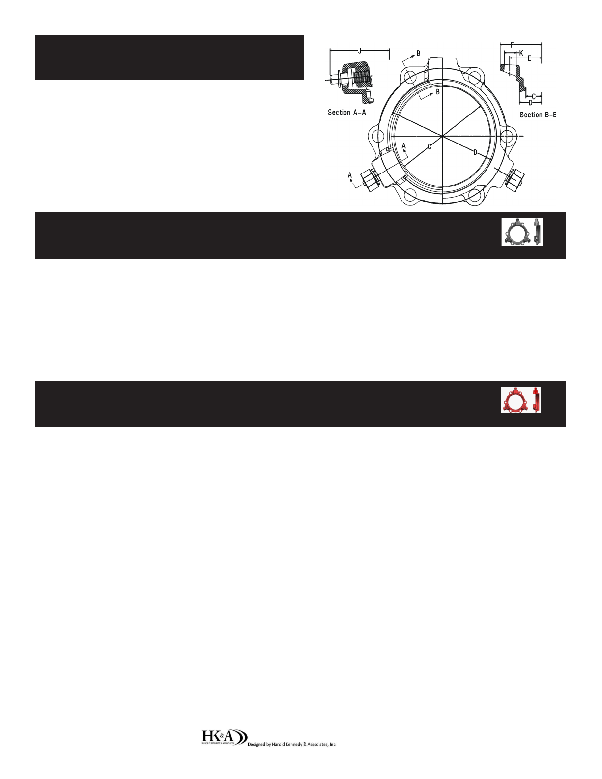
TUF Lock™ MJ Restraint Dimensions
Size
(inches) C D E F J K
3 4.08 4.88 6.19 7.67 9.82 3/4
4 4.93 5.92 7.50 8.98 10.67 7/8
6 7.03 8.02 9.50 10.98 12.77 7/8
8 9.18 10.17 11.75 13.23 14.92 7/8
10 11.23 12.22 14.00 15.70 16.97 7/8
12 13.33 14.32 16.25 17.95 19.07 7/8
14 15.44 16.40 18.75 20.43 21.18 7/8
16 17.54 18.50 21.00 22.88 23.28 7/8
18 19.64 20.60 23.25 25.43 25.38 7/8
20 21.74 22.70 25.50 27.50 27.48 7/8
24 25.94 26.90 30.00 32.00 31.68 7/8
Ductile TUF™ Lock Application Chart
Size Part Wedge T-Bolt Weight Weight Pressure
(inches) Number Quantity Quantity (lbs) (w/ Acc.) Rating (psi) Pipe OD
3 TLD-3 2 4 7.0 10.1 350 3.96
4 TLD-4 2 4 7.8 10.9 350 4.80
6 TLD-6 3 6 11.2 17.8 350 6.90
8 TLD-8 3 6 13.1 20.3 350 9.05
10 TLD-10 6 8 26.0 32.5 350 11.10
12 TLD-12 8 8 31.5 40.4 350 13.20
14 TLD-14 10 10 43.3 53.6 350 15.30
16 TLD-16 12 12 54.1 66.3 350 17.40
18 TLD-18 12 12 59.8 72.2 250 19.50
20 TLD-20 14 14 69.8 83.8 250 21.60
24 TLD-24 16 16 90.4 106.9 250 25.80
PVC TUF™ Lock Application Chart
Size Part Wedge T-Bolt Weight Weight Pressure
(inches) Number Quantity Quantity (lbs) (w/ Acc.) Rating (psi) Pipe OD
3 TLP-3 2 4 7.1 10.2 305 3.50
4 TLP-4 2 4 8.3 11.0 305 4.50-4.80
6 TLP-6 3 6 12.4 18.3 305 6.63-6.90
8 TLP-8 3 6 14.9 20.8 305 8.63-9.05
10 TLP-10 6 8 25.7 33.4 305 10.75-11.10
12 TLP-12 8 8 34.1 42.0 305 12.75-13.20
14 TLP-14 10 10 45.1 55.4 235 15.30
16 TLP-16 12 12 56.2 68.4 235 17.40
18 TLP-18 12 12 62.4 74.8 235 19.50
20 TLP-20 14 14 72.9 86.9 235 21.60
24 TLP-24 16 16 93.2 109.8 235 25.80
Suggested Specications: Bold Italicized language applies to Ductile and PVC TUF Lock™
Restraint glands shall be designed for use with and conform to the applicable requirements of ANSI / AWWA
C111.A21.11. Restraint gland product identication shall have traceability. Restraint glands shall have a minimum safety factor of 2:1. Restraint glands shall employ a single tooth wedge design and utilize torque limiting
nutsrequiring no more than 60 ft-lbs of torque to actuate wedges. Restraint devices shall accept out of round
pipe. Restraint devices shall not utilize stops, shall have a bolt and threaded wedge that can not be removed prior
to assembly. Mechanical Joint restraints shall be listed by Underwriters Laboratories in sizes 4”- 12”, and have
Factory Mutual approval in sizes 4” -12”. Specialty tools will not be required for installation. Restraint glands
shall be Tyler Union TUF Lock™ or approved equal.
Ductile TUF Lock™ will restrain pipe conforming to the requirements of ANSI/AWWA/C151/A21.51. Ductile Iron Pipegripping wedges shall be heat treated and hardened to a BHN range of 370-470.
PVC TUF Lock™ will restrain pipe manufactured to AWWA C900 / C905 and have working pressure ratings equal to the
pressure rating of the pipe on which they are used. Restraint glands shall accommodate 3”- 12” IPS pipe without the
removal of spacers or other modication of the device and conform to the requirements of ASTM 1674.
MECHANICAL JOINT C153 DUCTILE IRON
COMPACT FITTINGS
Sizes 3" thru 12" UL Listed For Fire Main Equipment
SAMPLE SPECIFICATIONS
Mechanical Joint watermain fittings with accessories, 3" through 48" shall be manufactured from Ductile Iron in
accordance with and meet all applicable terms and provisions of standards ANSI/AWWA C153/A21.53 ANSI/
AWWA C111/A21.11 (current revisions). Ductile Iron Mechanical Joint Fittings 3" through 24" shall be rated for
350 PSI working pressure. 30" through 48" shall be rated for 250 psi working pressure. Flanged ductile-iron
fittings in 24-in. (610 mm) and smaller sizes may be rated for 350 psi (2,413 kPa) with the use of special gaskets.
All coated fittings meet requirements of NSF-61.
NOTE - EXCEPTIONS: Mechanical Joint Fittings with flanged branches are rated for water pressure of 250 PSI.
NOTE: Fittings are CEMENT LINED and seal coated in accordance with ANSI/AWWA C104/A
21. 4
; also available
double cement-lined, bare or epoxy coated.
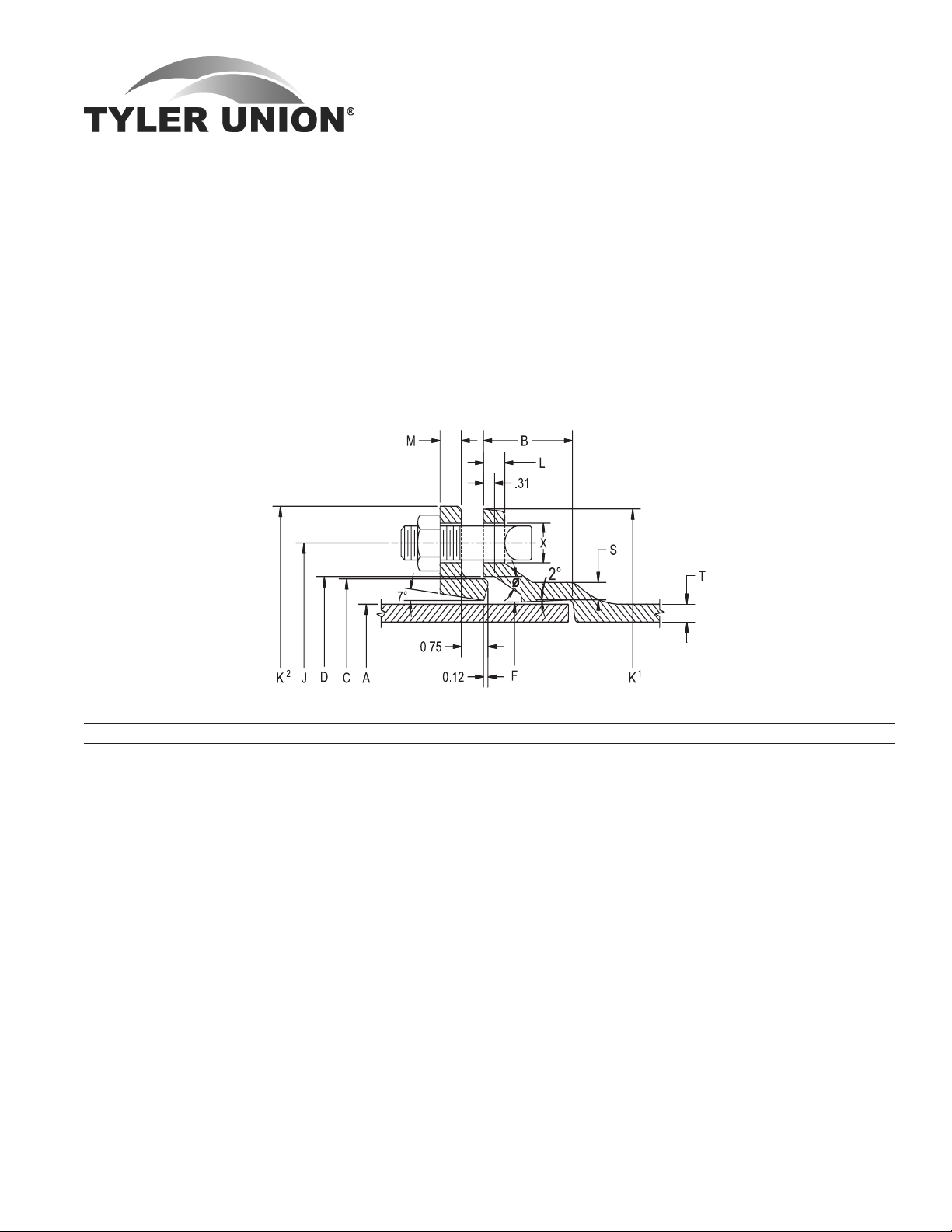
JOINT DIMENSIONS IN INCHES BOLTS
Size A Dia. B C Dia. D Dia. F Dia. J Dia. K 1 Dia. K2 Dia. L M S T X Size No.
3 3.96 2.50 4.84 4.94 4.06 6.19 7.62 7.69 .58 .62 .39 .33 ¾ Á x3 4
4 4.80 2.50 5.92 6.02 4.90 7.50 9.06 9.12 .60 .75 .39 .34 Â ¾x3½ 4
6 6.90 2.50 8.02 8.12 7.00 9.50 11.06 11.12 .63 .88 .43 .36 Â ¾x3½ 6
8 9.05 2.50 10.17 10.27 9.15 11.75 13.31 13.37 .66 1.00 .45 .38 Â ¾x3½ 6
10 11.10 2.50 12.22 12.34 11.20 14.00 15.62 15.62 .70 1.00 .47 .40 Â ¾x3½ 8
12 13.20 2.50 14.32 14.44 13.30 16.25 17.88 17.88 .73 1.00 .49 .42 Â ¾x3½ 8
14 15.30 3.50 16.40 16.54 15.44 18.75 20.31 20.25 .79 1.25 .56 .47 Â ¾x4 10
16 17.40 3.50 18.50 18.64 17.54 21.00 22.56 22.50 .85 1.31 .57 .50 Â ¾x4 12
18 19.50 3.50 20.60 20.74 19.64 23.25 24.83 24.75 1.00 1.38 .68 .54 Â ¾x4 12
20 21.60 3.50 22.70 22.84 21.74 25.50 27.08 27.00 1.02 1.44 .69 .57 Â ¾x4 14
24 25.80 3.50 26.90 27.04 25.94 30.00 31.58 31.50 1.02 1.56 .75 .61 Â ¾x4½ 16
30 32.00 4.00 33.29 33.46 32.17 36.88 39.12 39.12 1.31 2.00 .82 .66 1¿ 1 x5½ 20
36 38.30 4.00 39.59 39.76 38.47 43.75 46.00 46.00 1.45 2.00 1.00 .74 1¿ 1 x5½ 24
42 44.50 4.00 45.79 45.96 44.67 50.62 53.12 53.12 1.45 2.00 1.25 .82 1À 1¼x6½ 28
48 50.80 4.00 52.09 52.26 50.97 57.50 60.00 60.00 1.45 2.00 1.35 .90 1À 1¼x6½ 32
Tyler Utilities Division • 11910 CR 492 • Tyler, Texas 75706 • (800) 527-8478
02/01/08 Union Foundry Company • Box 309 • Anniston, Alabama 36202 • (800) 226-7601 1
MECHANICAL JOINT C153 DUCTILE IRON
COMPACT FITTINGS
Sizes 3" thru 12" UL Listed For Fire Main Equipment
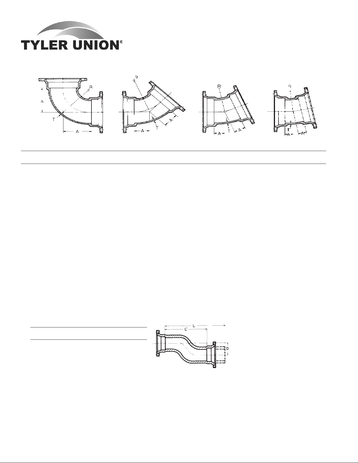
BENDS
90° Bends (1/4) 45° Bends (1/8) 22½° Bends (1/16) 11¼° (1/32)
Dimensions Dimensions Dimensions Dimensions
Size T A R Weight A R Weight A R Weight A R Weight
3 .34 3.5 2.5 19 2.00 2.41 17 1.50 2.51 15 1.25 2.53 16
4 .35 4.0 3.0 26 2.50 3.56 22 1.75 3.81 20 1.50 5.12 20
6 .37 6.5 6.0 49 3.50 7.25 39 2.25 6.35 31 1.50 5.12 29
8 .39 7.5 7.0 64 4.00 8.44 56 2.85 11.80 50 2.06 15.80 45
10 .41 9.5 9.0 102 5.01 10.88 78 3.35 14.35 66 2.32 18.36 59
12 .43 10.5 10.0 129 5.98 13.25 102 3.86 16.90 87 2.56 20.90 82
14 .51 12.0 11.5 214 5.50 12.06 155 3.93 17.25 142 2.59 21.25 136
16 .52 13.0 12.5 273 5.98 13.25 204 3.98 17.50 178 2.62 21.50 157
18 .59 15.5 14.0 411 6.50 12.36 292 7.50 30.19 286 3.00 60.84 283
20 .60 17.0 15.5 519 7.00 13.59 372 8.50 35.19 376 3.50 71.07 374
24 .62 17.0 15.5 721 7.50 14.89 490 9.00 37.69 512 3.50 76.12 487
30 .66 21.50 19.0 930 10.50 9.31 716 6.75 21.36 665 4.75 22.84 600
36 .74 24.50 22.0 1450 11.50 21.73 1110 7.75 26.39 960 5.00 25.38 820
42 .82 29.25 26.7 2205 14.00 27.76 1610 9.00 32.68 1350 6.00 35.54 1180
48 .90 33.25 30.75 2990 15.00 30.17 2090 10.00 27.70 1760 6.50 40.61 1475
*OFFSETS
MJ x MJ MJ x PE
Dimensions Weights
Size D L1 L MJxMJ MJxPE
4 6 10 -- 45 --
4 12 16 -- 55 - 4 18 22 -- 65 - 4 24 28 -- 75 - 6 6 12 17.5 41 54
6 12 18 -- 65 - 6 18 24 -- 75 - 6 24 30 -- 85 - 8 6 13 -- 84 - 8 12 19 -- 90 - 8 18 25 -- 100 --
* Not included in AWWA C153.
Tyler Utilities Division • 11910 CR 492 • Tyler, Texas 75706 • (800) 527-8478
2 Union Foundry Company • Box 309 • Anniston, Alabama 36202 • (800) 226-7601 02/01/08
MECHANICAL JOINT C153 DUCTILE IRON
COMPACT FITTINGS
Sizes 3" thru 12" UL Listed For Fire Main Equipment
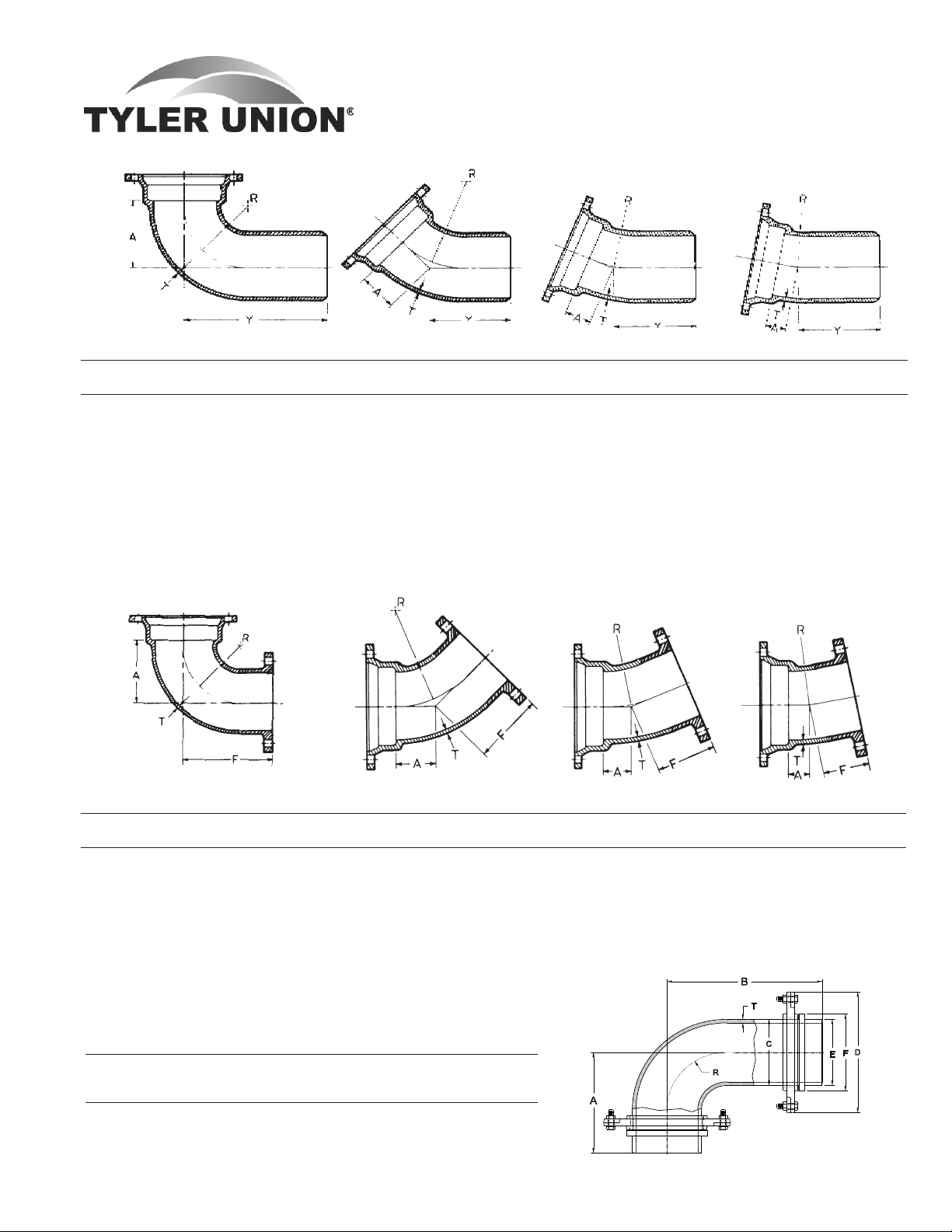
BENDS
90° Bend MJ x PE (1/4) 45° Bend MJ x PE (1/8) 22½° Bend MJ x PE (1/16) 11¼° Bend MJ x PE (1/32)
Dimensions Dimensions Dimensions Dimensions
Size T A Y R Weight A Y R Weight A Y R Weight A Y R Weight
3 .34 3.5 9.0 2.5 18 2.0 7.5 2.41 17 1.50 7.00 2.51 19 1.25 6.75 7.62 15
4 .35 4.0 9.5 3.0 26 2.5 8.0 3.56 22 1.75 7.25 3.81 20 1.50 7.00 5.12 20
6 .37 6.0 11.5 5.0 45 3.2 8.7 5.49 38 2.25 7.75 6.35 33 1.50 7.00 5.12 32
8 .39 7.5 13.0 7.0 64 4.0 9.5 8.44 55 2.84 8.34 11.80 51 2.05 7.55 15.80 44
10 .41 9.5 15.0 9.0 108 5.0 10.5 10.88 78 3.35 8.85 14.35 66 2.31 7.81 18.36 60
12 .43 9.0 14.4 6.0 114 6.0 11.5 13.25 104 3.50 9.00 12.70 89 2.56 8.06 20.90 79
14 .51 12.0 20.0 11.5 219 5.5 13.4 10.85 165 3.93 11.93 17.25 152 2.59 10.59 21.25 137
16 .52 13.0 21.0 12.5 254 6.0 14.0 13.25 206 3.98 11.98 17.50 181 2.62 10.62 21.50 161
24 .62 17.0 25.0 15.5 710 7.5 16.6 14.69 460 9.00 17.66 37.69 455 9.00 26.12 12.00 475
30 .68 21.5 30.5 -- 865 10.5 19.5 -- 715 6.75 15.75 -- 600 -- -- -- --
90° Bend MJ x Flange 45° Bend MJ x Flange 22½° Bend MJ x Flange 11¼° Bend MJ x Flange
(1/4) (1/8) (1/16) (1/32)
Dimensions Dimensions Dimensions Dimensions
Size T A R F Weight A R F Weight A R F Weight A R F Weight
3 .34 3.5 2.5 5.5 21 ... ... .. .. ... ... .. .. ... ... .. ..
4 .35 4.0 3.0 6.5 28 2.50 3.56 4.0 34 1.75 3.81 4.0 34 1.50 5.12 4.0 19
6 .37 6.0 5.0 8.0 45 3.25 5.49 5.0 57 2.25 5.35 5.0 57 1.50 5.12 5.0 30
8 .39 7.5 7.0 9.0 73 4.25 7.93 5.5 83 2.50 7.62 5.5 83 1.75 7.70 5.5 50
10 .41 9.5 9.0 11.0 113 5.00 9.76 6.5 122 3.00 10.16 6.5 122 2.00 10.25 6.5 75
12 .43 10.5 10.0 12.0 141 6.00 12.19 7.5 159 3.50 12.70 7.5 159 2.25 12.82 7.5 88
14 .51 12.0 11.5 14.0 217 5.50 10.85 8.5 207
16 .52 13.0 12.5 15.0 280 6.00 12.02 9.5 290
90° Swivel x Swivel Hydrant Ell
Dimensions
Size T A B C D E F R
*Weight
6 .37 10.5 15.5 6.90 11.2 6.81 7.98 6.0 74
* Weight includes two swivel glands.
Tyler Utilities Division • 11910 CR 492 • Tyler, Texas 75706 • (800) 527-8478
02/01/08 Union Foundry Company • Box 309 • Anniston, Alabama 36202 • (800) 226-7601 3
MECHANICAL JOINT C153 DUCTILE IRON
COMPACT FITTINGS
Sizes 3" thru 12" UL Listed For Fire Main Equipment
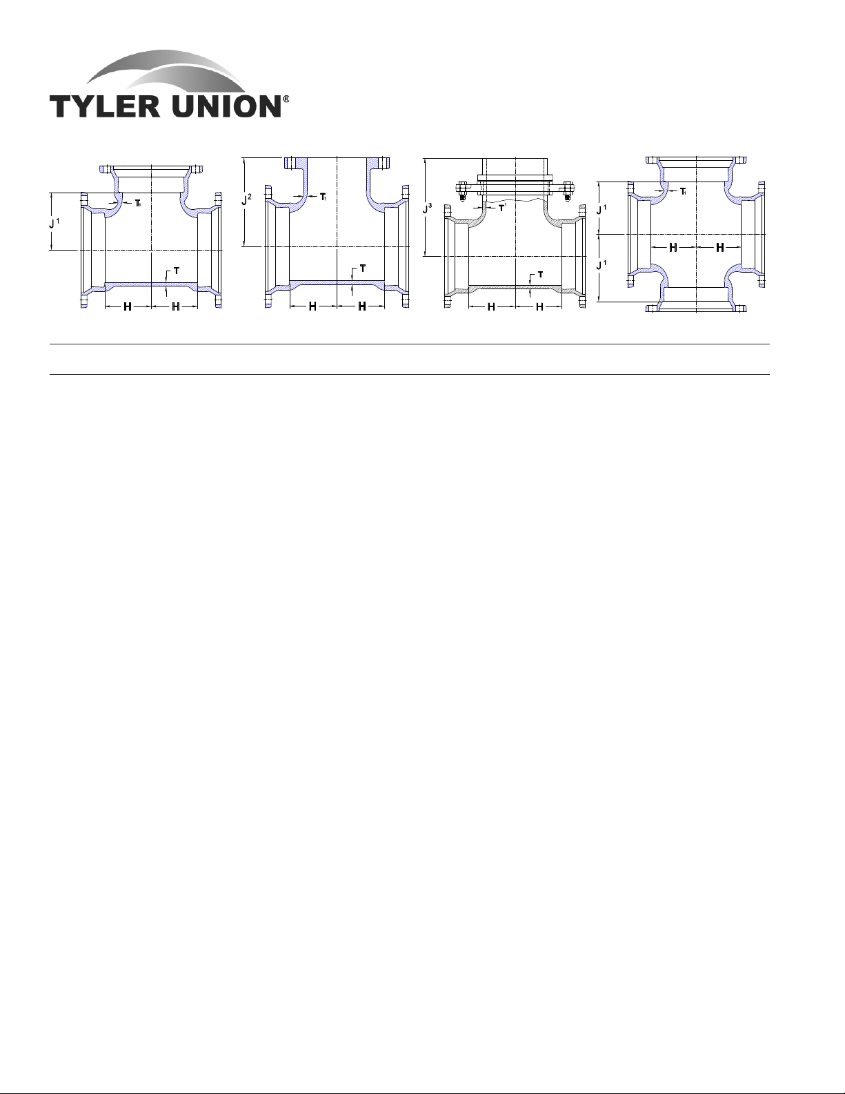
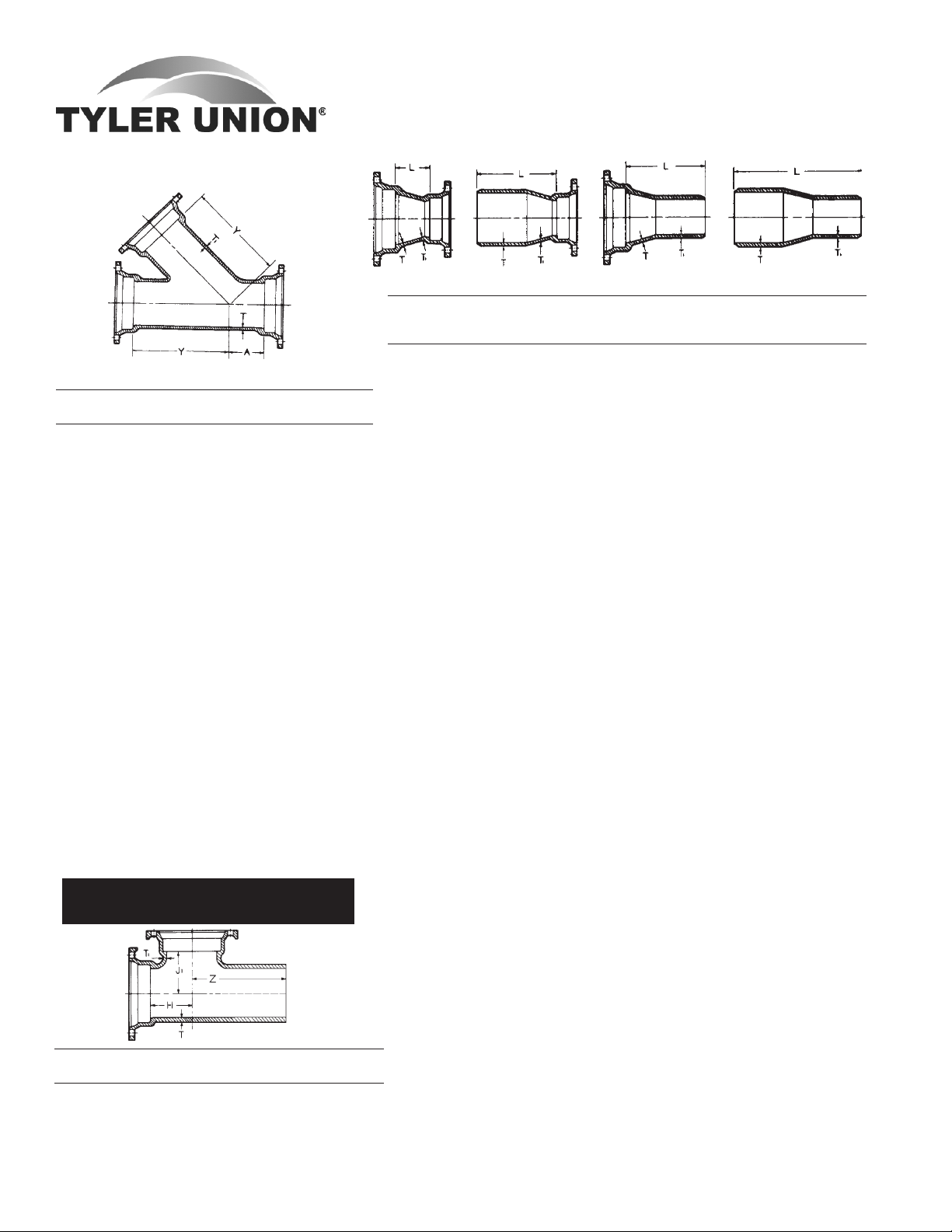
TEES
MJ Tee MJ x FE Tee MJ x Swivel Tee Cross
Dimensions Weights
Size T T1 H J1 J2 J3 MJ MJxFE †MJxS Cross
3 .34 .34 3.5 3.50 5.5 ... 26 29 ... 31
4x3 .35 .34 3.5 4.00 6.5 ... 35 34 ... 39
4 .35 .35 4.0 4.00 6.5 ... 36 39 ... 45
6x3 .37 .34 4.0 4.00 6.5 ... 51 54 ... ...
6x4 .37 .35 4.0 5.00 8.0 ... 52 57 ... 62
6 .37 .37 5.0 5.00 8.0 10.50 66 68 77 79
8x3 .39 .34 4.0 6.50 9.0 ... 56 ... ... ...
8x4 .39 .35 4.5 6.50 9.0 ... 72 82 ... 84
8x6 .39 .37 5.5 6.50 9.0 11.50 79 81 105 98
8 .39 .39 6.5 6.50 9.0 11.50 90 101 116 112
10x3 .41 .34 4.0 7.50 11.0 ... 80 ... ... ...
10x4 .41 .35 4.5 7.50 11.0 ... 82 92 ... 98
10x6 .41 .37 5.5 7.50 11.0 13.00 99 116 114 121
10x8 .41 .39 6.5 7.50 11.0 13.00 116 128 138 135
10 .41 .41 7.5 7.50 11.0 ... 132 144 ... 156
12x3 .43 .34 4.0 8.75 12.0 ... 99 ... ... ...
12x4 .43 .35 4.5 8.75 12.0 ... 108 118 ... 119
12x6 .43 .37 5.5 8.75 12.0 14.25 119 133 132 138
12x8 .43 .39 6.5 8.75 12.0 14.25 126 146 149 149
12x10 .43 .41 7.5 8.75 12.0 ... 159 174 ... 187
12 .43 .43 8.75 8.75 12.0 ... 171 198 ... 202
14x6 .51 .44 6.5 10.50 14.0 16.00 183 205 211 210
14x8 .51 .45 7.5 10.50 14.0 ... 211 ... ... 231
14x10 .51 .46 8.5 10.50 14.0 ... 229 244 ... 255
14x12 .51 .47 9.5 10.50 14.0 ... 245 284 ... 269
14 .51 .51 10.5 10.50 14.0 ... 281 291 ... 299
16x6 .52 .45 6.5 11.50 15.0 17.00 222 230 243 250
16x8 .52 .46 7.5 11.50 15.0 ... 245 248 ... 264
16x10 .52 .47 8.5 11.50 15.0 ... 265 287 ... 286
16x12 .52 .48 9.5 11.50 15.0 ... 277 312 ... 312
16x14 .52 .51 10.5 11.50 15.0 ... 317 348 ... ...
16 .52 .52 11.5 11.50 15.0 ... 337 324 ... 457
30 .66 .66 22.0 22.00 ... ... ... ... ... 1840
36 .74 .74 26.0 26.0 ... ... ... ... ... 2655
† Weights include swivel gland
CROSS
Tyler Utilities Division • 11910 CR 492 • Tyler, Texas 75706 • (800) 527-8478
4 Union Foundry Company • Box 309 • Anniston, Alabama 36202 • (800) 226-7601 02/01/08
MECHANICAL JOINT C153 DUCTILE IRON
COMPACT FITTINGS
Sizes 3" thru 12" UL Listed For Fire Main Equipment
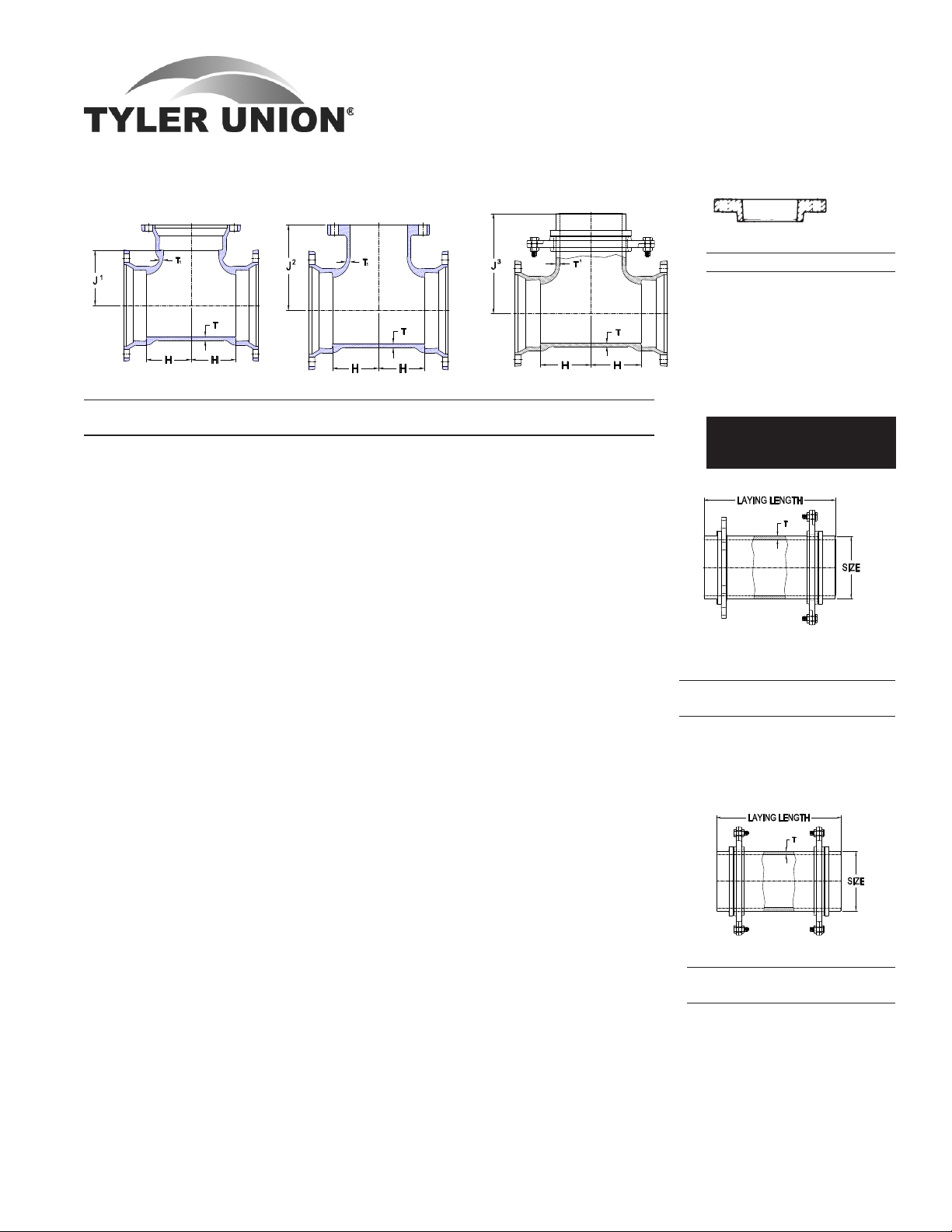
TEES (Continued)
MJ Tee MJ x FE Tee MJ x Swivel Tee
Dimensions Weights
Size T T1 H J1 J2 J3 MJ MJxFE †MJxS
18x6 .59 .44 6.5 14.5 15.5 18.0 275 261 279
18x8 .59 .45 7.5 14.5 14.5 ... 280 351 ...
18x10 .59 .47 8.5 12.5 ... ... 286 ... ...
18x12 .59 .49 9.5 12.5 ... ... 372 ... ...
18x14 .59 .56 10.5 12.5 ... ... 415 ... ...
18x16 .59 .57 11.5 12.5 ... ... 445 ... ...
18 .59 .59 13.0 12.5 ... ... 490 ... ...
20x6 .60 .44 7.0 16.0 17.0 19.5 335 362 358
20x8 .60 .45 8.0 14.0 ... ... 390 ... ...
20x10 .60 .47 9.0 14.0 ... ... 417 ... ...
20x12 .60 .49 10.0 14.0 ... ... 460 ... ...
20x14 .60 .56 11.0 14.0 ... ... 475 ... ...
20x16 .60 .57 12.0 14.0 ... ... 530 ... ...
20x18 .60 .59 13.0 14.0 ... ... 560 ... ...
20 .60 .60 14.0 14.0 ... ... 605 ... ...
24x6 .62 .44 7.0 18.0 19.0 21.5 465 451 457
24x8 .62 .45 8.0 16.0 ... ... 475 ... ...
24x10 .62 .47 9.0 16.0 ... ... 516 ... ...
24x12 .62 .49 10.0 18.0 ... ... 549 580 ...
24x14 .62 .56 11.0 16.0 ... ... 585 ... ...
24x16 .62 .57 12.0 19.5 ... ... 625 744 ...
24x18 .62 .59 13.0 16.0 ... ... 675 ... ...
24x20 .62 .60 15.0 17.0 ... ... 740 ... ...
24 .62 .62 17.0 17.0 ... ... 844 ... ...
30x6 .66 .36 7.00 20.0 ... ... 700 ... ...
30x8 .66 .38 8.50 20.0 ... ... 739 ... ...
30x12 .66 .42 10.0 20.0 ... ... 739 ... ...
30x16 .66 .50 12.5 20.0 ... ... 959 ... ...
30x20 .66 .57 15.0 20.0 ... ... 995 ... ...
30x24 .66 .61 16.0 20.0 ... ... 1160 ... ...
30 .66 .66 20.0 20.0 ... ... 1323 ... ...
36x16 .74 .50 12.5 23.5 ... ... 1350 ... ...
36x24 .74 .61 16.0 23.5 ... ... 1498 ... ...
36x30 .74 .66 20.0 23.5 ... ... 1555 ... ...
36 .74 .74 23.5 23.5 ... ... 1900 ... ...
42 .82 .82 30.0 30.0 ... ... 3175 ... ...
† Weights include swivel gland.
MJ GLANDS
Glands
Size Weight Size Weight
3 3 12 10
4 4 14 17
6 5 16 21
8 6 18 22
10 9 20 32
24 37
Swivel Glands, page 19-20
Retainer Glands, page 7
Swivel x Solid Adapter
with Swivel Gland
Size by Wall
Laying Length Thickness Weight
6x13 .37 52
6x18 .37 65
6x24 .37 69
8x12 .39 52
Swivel x Swivel Adapter
Size by Wall
Laying Length Thickness Weight
6x12 .37 28
6x18 .37 49
6x24 .37 52
Tyler Utilities Division • 11910 CR 492 • Tyler, Texas 75706 • (800) 527-8478
02/01/08 Union Foundry Company • Box 309 • Anniston, Alabama 36202 • (800) 226-7601 5
MECHANICAL JOINT C153 DUCTILE IRON
COMPACT FITTINGS
Sizes 3" thru 12" UL Listed For Fire Main Equipment
WYES/LATERAL
REDUCERS
MJ x MJ MJSEBxPE MJLEBxPE PE x PE
Dimensions
MJ SEB LEB PE Weights
Size T T1 L L L L MJ SEB LEB PE
4x3 .35 .34 3.0 8.5 8.5 14.0 18 17 17 18
*Wyes
Dimensions
Size A Y T T1 Weights
3 2.5 7.5 .34 .34 36
4x3 2.0 8.5 .35 .34 39
4 2.5 8.5 .35 .35 45
6x4 1.5 11.0 .37 .35 67
6 3.0 13.0 .37 .37 85
8x4 0.5 13.0 .39 .35 86
8x6 2.0 14.5 .39 .37 109
8 3.5 16.0 .39 .39 117
10x4 0.0 15.0 .41 .35 112
10x6 1.0 16.0 .41 .37 129
10x8 2.5 17.0 .41 .39 162
10 3.5 19.0 .41 .41 199
12x4 0.0 16.5 .43 .35 141
12x6 1.5 18.5 .43 .37 170
12x8 1.5 18.5 .43 .39 177
12x10 3.0 20.0 .43 .41 216
12 4.5 22.5 .43 .43 269
14 6.0 25.0 .51 .51 476
†
16x6 0.0 21.0 .52 .45 300
16x8 0.5 22.5 .52 .46 349
16x12 3.5 25.0 .52 .48 471
†
16 6.5 28.0 .52 .52 635
†
* Not included in AWWA C153.
† Rated at 250 psi.
MJ x FE Flange Dimensions are on inside
front cover.
6x3 .37 .34 5.0 10.5 10.5 16.0 28 25 27 20
6x4 .37 .35 4.0 9.5 9.5 15.0 28 26 27 26
8x4 .39 .35 5.0 10.5 10.5 16.0 36 34 36 33
8x6 .39 .37 4.0 9.5 9.5 15.0 39 38 39 30
10x4 .41 .35 7.0 12.5 12.5 18.0 53 46 51 ...
10x6 .41 .37 5.0 10.5 10.5 16.0 59 48 52 49
10x8 .41 .39 4.0 9.5 9.5 15.0 54 52 52 47
12x4 .43 .35 9.0 14.5 14.5 20.0 67 61 68 60
12x6 .43 .37 7.0 12.5 12.5 18.0 64 58 66 54
12x8 .43 .39 5.0 10.5 10.5 16.0 57 62 65 60
12x10 .43 .41 4.0 9.5 9.5 15.0 63 61 65 57
14x6 .51 .44 9.0 17.0 14.5 22.5 104 107 112 ...
14x8 .51 .45 7.0 15.0 12.5 20.5 104 107 108 ...
14x10 .51 .46 5.0 13.0 10.5 18.5 100 102 100 ...
14x12 .51 .47 4.0 12.0 9.5 17.5 100 101 100 100
16x6 .52 .45 11.0 19.0 16.5 24.5 132 131 141 128
16x8 .52 .46 9.0 17.0 14.5 22.5 136 128 136 136
16x10 .52 .47 7.0 15.0 12.5 20.5 128 124 128 123
16x12 .52 .48 5.0 13.0 10.5 18.5 120 123 119 113
16x14 .52 .51 4.0 12.0 12.0 20.0 140 139 138 133
18x8 .59 .45 14.0 22.0 19.5 27.5 201 180 195 ...
18x10 .59 .47 12.0 20.0 17.5 25.5 196 180 185 ...
18x12 .59 .49 10.0 18.0 15.5 23.5 175 170 190 ...
18x14 .59 .56 8.0 16.0 16.0 24.0 180 181 200 ...
18x16 .59 .57 7.0 15.0 15.0 23.0 194 180 190 ...
20x10 .60 .47 14.0 22.0 19.4 27.5 225 210 210 ...
20x12 .60 .49 12.0 20.0 17.5 25.5 214 208 210 ...
20x14 .60 .56 10.0 18.0 17.8 26.0 208 198 205 ...
20x16 .60 .57 8.0 16.0 15.8 24.0 225 215 222 ...
20x18 .60 .59 7.0 15.0 15.0 23.0 233 220 ... ...
24x12 .62 .49 16.0 24.0 21.4 29.5 320 302 300 ...
24x14 .62 .56 14.0 22.0 21.8 30.0 314 325 322 ...
24x16 .62 .57 12.0 20.0 19.8 28.0 325 319 340 ...
24x18 .62 .59 10.0 18.0 18.0 26.0 325 310 ... ...
24x20 .62 .60 8.0 16.0 16.0 24.0 315 305 ... ...
30x16 .66 .50 30.0 39.0 ... ... 475 565 ... ...
30x18 .66 .54 28.0 37.0 ... ... 495 590 ... ...
30x20 .66 .57 24.0 33.0 ... ... 525 560 ... ...
MJ x PE x MJ Tee
Dimensions
Size T T
1
H J
1
Z Weights
6 .37 .37 5.0 5.0 11.5 57
8x6 .39 .37 5.5 6.5 11.5 79
8 .39 .39 6.5 6.5 12.5 83
10 .41 .41 7.5 7.5 13.0 133
Tyler Utilities Division • 11910 CR 492 • Tyler, Texas 75706 • (800) 527-8478
6 Union Foundry Company • Box 309 • Anniston, Alabama 36202 • (800) 226-7601 02/01/08
30x24 .66 .61 10.0 24.5 ... ... 478 495 ... ...
36x16 .74 .50 ... ... ... ... ... 890 ... ,,,
36x20 .74 .57 ... 45.0 ... ... ... 874 ... ...
36x24 .74 .61 19.0 33.0 ... ... 770 746 ... ...
36x30 .74 .66 ... 24.5 ... ... ... 725 ... ...
42x30 .82 .66 20.0 ... ... ... 1185 ... ... ...
48x30 .90 .66 40.0 ... ... ... 1505 ... ... ...
MECHANICAL JOINT C153 DUCTILE IRON
COMPACT FITTINGS
Sizes 3" thru 12" UL Listed For Fire Main Equipment
SOLID & TAPPED PLUGS & CAPS
3"-12" 14"-24" 3"-12" 14"-24"
MJ Plug MJ Cap
Dimensions Max. Weights
Size T Tap Plugs Caps
3 .46 2 9 8
4 .46 2 9 10
6 .46 2 18 18
8 .46 2 25 26
10 .56 2 36 32
12 .56 2 47 46
14 .62 2 76 85
16 .62 2 98 94
18 .65 2 138 121
20 .66 2 158 149
24 .68 2 223 210
30 .66 2 355 345
36 .74 2 688 626
MJ x FE Flange
TAPPED TEE
Dimensions are
on inside front
cover.
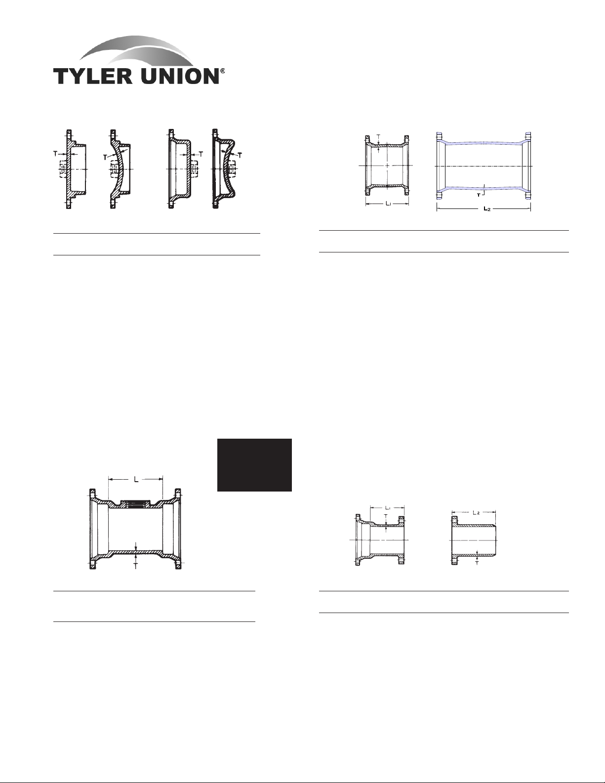
SOLID SLEEVES
Short Long
Dimensions Weights
Size T L1 L2 Short Long
3 .34 7.5 12 13 22
4 .35 7.5 12 19 25
6 .37 7.5 12 28 39
8 .39 7.5 12 38 55
10 .41 7.5 12 48 68
12 .43 7.5 12 62 81
14 .56 9.5 15 116 146
16 .57 9.5 15 138 174
18 .68 9.5 15 160 230
20 .69 9.5 15 212 269
24 .75 9.5 15 272 380
30 .66 15.0 15 500 ...
30 .66 ... 24 ... 640
36 .74 15.0 15 725 ...
36 .74 ... 24 ... 925
42 .82 ... 24 ... 1146
48 .90 ... 24 ... 1455
ADAPTERS
MJ Tapped Tee (2" Tap)
Dimensions
Size T L Max. Tap Weights
3 .34 6 2 19
4 .35 6 2 23
6 .37 6 2 35
8 .39 6 2 54
10 .41 6 2 68
12 .43 6 2 88
16 .52 6 2 164
Tyler Utilities Division • 11910 CR 492 • Tyler, Texas 75706 • (800) 527-8478
02/01/08 Union Foundry Company • Box 309 • Anniston, Alabama 36202 • (800) 226-7601 7
MJ x FE FE x PE
Dimensions Weights
Size T L1 L2 MJxFE FExPE
3 .34 6 12 18 ...
4 .35 6 12 26 23
6 .37 6 12 36 35
8 .39 6 12 50 50
10 .41 6 12 60 69
12 .43 6 12 88 88
14 .51 6 12 127 ...
16 .52 6 12 155 149
20 .60 6 ... 275 ...
30 .66 7 ... 470 ...
36 .74 8 ... 750 ...
MECHANICAL JOINT C153 DUCTILE IRON
COMPACT FITTINGS
Sizes 3" thru 12" UL Listed For Fire Main Equipment
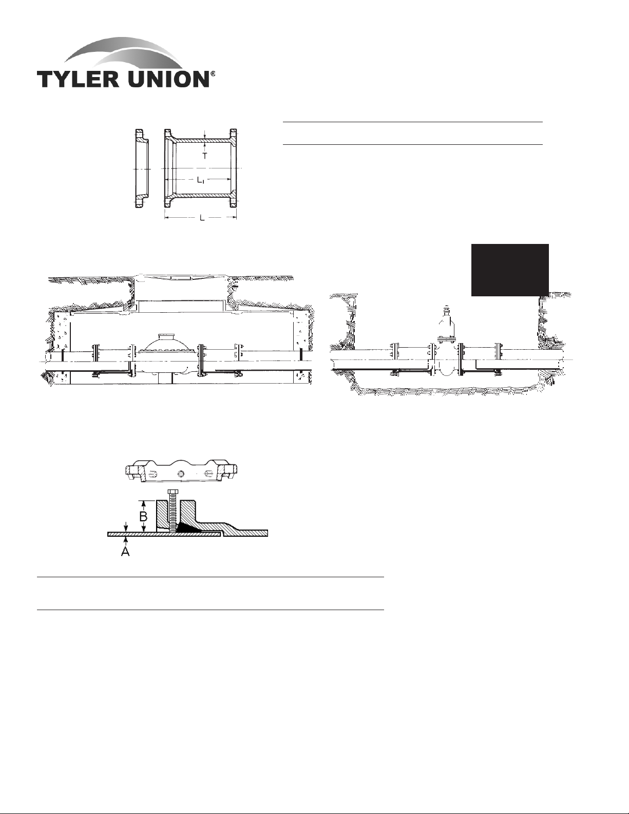
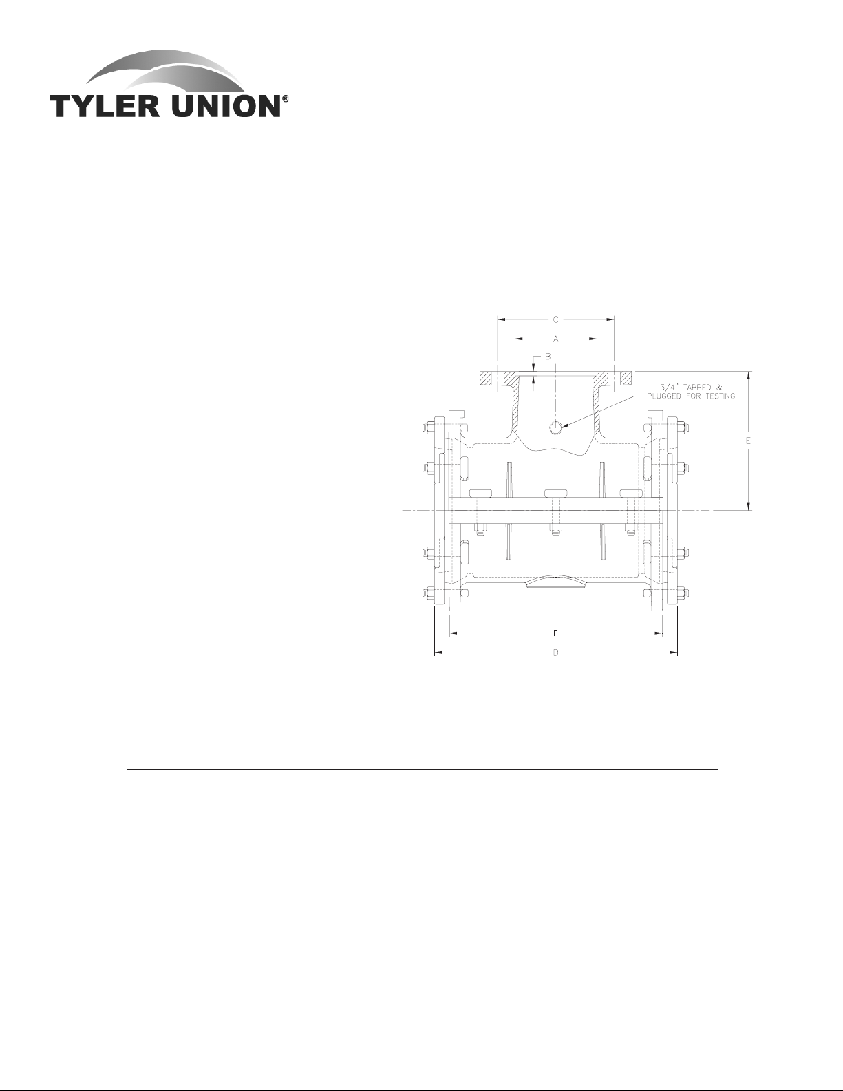
DUAL PURPOSE CUTTING-IN SLEEVE
Flanged ends are faced and drilled per ANSI/AWWA C110/A21.10. Mechanical joint ends are designed to receive both standard and oversize gray or ductile iron pipe as shown above.
TYPICAL CUTTING-IN SLEEVE INSTALLATIONS
METER SETTINGS
MJ x FE
Cutting-In Sleeve with Dual Purpose Accessories
Dimensions Shipping Wt.
Size For Pipe Size L L1 T Assembled
4 4.80-5.00 O.D. 10 9.5 .35 33
6 6.90-7.10 O.D. 10 9.5 .37 50
8 9.05-9.30 O.D. 10 9.5 .39 67
10 11.10-11.40 O.D. 10 9.5 .41 122
12 13.20-13.50 O.D. 10 9.5 .43 157
MJ x FE Flange
Dimensions are
VALVE
INSTALLATIONS
on inside front
cover.
Pipe Wall Thickness:
*RETAINER GLAND ASSEMBLY
Sizes 3"-12" are recommended for ductile
iron pipe class 50 thru 56. Sizes 14" thru 24"
are recommended for ductile iron pipe class
53 thru 56.
DUCTILE IRON RETAINER
GLANDS
Mechanical Joint Retainer Glands are
designed to provide a method for restraining mechanical joint pipe and fittings
and other standardized mechanical joints
See Installations Instructions ........................................................ Page 50
Pressure Gland Pipe O.D. D.I. Pipe No of Size of
Rating, O.D. O.D. Wall Set Set Gland Weight
Size psi B A Class Screws Screws Weight w/Acces.
3 350 7.69 3.96 50-56 4 Á x2 5 7
4 350 9.12 4.80 50-56 4 Á x2 6 13
6 350 11.12 6.90 50-56 6 Á x2 11 20
8 250 13.37 9.05 50-56 9 Á x2 13 25
10 250 15.62 11.10 50-56 12 Á x2 18 33
12 150 17.88 13.20 50-56 16 Á x2 23 38
14 250 20.25 15.30 53-56 20 Á x2½ 44 55
16 200 22.50 17.40 53-56 24 Á x2½ 51 64
18 200 24.75 19.50 53-56 24 Á x2½ 62 72
20 200 27.00 21.60 53-56 28 Á x3 73 91
24 150 31.50 25.80 53-56 32 Á x3 93 118
* Not included in AWWA C110
Tyler Utilities Division • 11910 CR 492 • Tyler, Texas 75706 • (800) 527-8478
8 Union Foundry Company • Box 309 • Anniston, Alabama 36202 • (800) 226-7601 02/01/08
against possible joint separation, rupture
or blow-out caused by internal water pressure.
The set screws are square-headed
with Type C knurled cup points, and are
shipped already assembled in the Glands.
They are manufactured of 4140 grade
alloy steel, and are heat treated to a Rockwall “C” 45/53 case hardness. Tee-head
bolts and gaskets are not included, but
may be ordered separately. Recommended torque for set screws is 75 foot pounds,
and set screws on opposite sides of the
glands should be tightened alternately.
Tee-head bolt hole size and spacing are equal to MJ Glands as shown in
AWWA C-111. Standard mechanical Joint
gaskets as shown in C-111 should be
used.
4" Size
MECHANICAL JOINT DUCTILE IRON
COMPACT SPLIT REPAIR GLANDS
6"-8"-10"-12" Sizes
MJ Compact Split Repair Glands
Inside Diameter Bolt Circle Weight
Size (+.07-.03) (+-.06) Lbs.
4 4.90 7.50 4.0
6 7.00 9.50 5.0
8 9.15 11.75 6.0
10 11.20 14.00 7.7
12 13.50 16.25 10.2
Split glands work with standard MJ gaskets and standard
T-head bolts. Glands are shipped in halves and do not need
separate bolts. T-head bolts alone hold the halves together.
Tyler Utilities Division • 11910 CR 492 • Tyler, Texas 75706 • (800) 527-8478
02/01/08 Union Foundry Company • Box 309 • Anniston, Alabama 36202 • (800) 226-7601 9
COMPACT
DUCTILE IRON MJ TAPPING SLEEVES
SAMPLE SPECIFICATION
Ductile Iron Mechanical Joint Tapping Sleeves furnished by Tyler Pipe Company, Tyler, Texas are produced in accordance with manufacturer's standards. Chemical and physical properties of the ductile iron are in accordance
with the requirements of ANSI/AWWA C110/A21.10-82.
Recess dimensions are per Manufacturer's Standardization Society standard practice SP-60.
General Installation Instructions for Tyler MJ Tapping Sleeves
1. Clean pipe - insert side gasket into back half of gasket grooves. Make sure ends are flush with or slightly protrude into the end gasket seating area.
2. Bolt sleeve halves together and trim side gaskets as necessary. MAKE SURE SLEEVE WILL ROTATE FREELY ON
PIPE.
3. Install end gaskets, locating cut ends 90° from
side gasket. If pipe is maximum OD, stretch
gasket to make certain cut ends match with no
gap in between.
4. Install glands and bolts - rotate sleeve to desired
position. Be sure pipe is centered inside the sleeve.
5. Tighten gland bolts alternately, using 80 to 90
foot pounds.
6. After assembly, PRESSURE TEST ALL JOINTS BEFORE TAPPING. If additional tightening is
required, release pressure and relax tension on
gland bolts before tightening side bolts.
For Cast Iron or Ductile Iron Pipe
Mechanical joint tapping sleeves - for 6" through
12" cast iron or ductile iron pipe.
• Outlet flange per ANSI/AWWA C110/A21.10
• Gaskets furnished.
• Working pressure-200 p.s.i.
Tapping Sleeve for
Cast Iron/Ductile Iron
O.D. Range
Dimensions DI Weight
Size A B C D E F Min. Max. DI
6x4 5.016 .250 7.50 15.75 8.00 12.75 6.85 7.15 104
6 7.016 .312 9.50 15.75 8.00 12.75 6.85 7.15 108
8x4 5.016 .250 7.50 16.50 9.00 13.50 9.00 9.35 134
8x6 7.016 .312 9.50 16.50 9.00 13.50 9.00 9.35 140
8 9.016 .312 11.75 16.50 9.00 13.50 9.00 9.35 148
10x4 5.016 .250 7.50 24.00 11.00 20.75 11.04 11.45 236
10x6 7.016 .312 9.50 24.00 11.00 20.75 11.04 11.45 240
10x8 9.016 .312 11.75 24.00 11.00 20.75 11.04 11.45 246
10 11.016 .312 14.25 24.00 11.00 20.75 11.04 11.45 257
12x4 5.016 .250 7.50 26.50 12.00 23.25 13.14 13.56 273
12x6 7.016 .312 9.50 26.50 12.00 23.25 13.14 13.56 286
12x8 9.016 .312 11.75 26.50 12.00 23.25 13.14 13.56 292
12x10 11.016 .312 14.25 26.50 12.00 23.25 13.14 13.56 303
12 13.016 .312 17.00 26.50 12.00 23.25 13.14 13.56 320
Tyler Utilities Division • 11910 CR 492 • Tyler, Texas 75706 • (800) 527-8478
10 Union Foundry Company • Box 309 • Anniston, Alabama 36202 • (800) 226-7601 02/01/08
DUCTILE IRON C110 FULL BODY
MECHANICAL JOINT DIMENSIONS
SAMPLE SPECIFICATION
Mechanical Joint watermain fittings with accessories, 2" through 48" shall be produced of Ductile Iron in accordance with and
meet all applicable terms and provisions of standards ANSI/AWWA C110/A21.10 ANSI/AWWA C111/A21.11 (current revisions). Ductile Iron Mechanical Joint Fittings 3" through 24" shall be rated for 350 PSI working pressure. All Ductile Iron Mechanical Joint Fittings 30" through 48" shall be rated for 250 PSI working pressure. Flanged ductile-iron fittings in 24-in. (610
mm) and smaller sizes may be rated for 350 psi (2,413 kPa) with the use of special gaskets.
NOTE - EXCEPTIONS: Mechanical Joint Fittings with flanged branches and 14" and larger caps and plugs are rated for water
pressure of 250 PSI.
NOTE: Fittings are CEMENT-LINED and seal coated in accordance with ANSI/AWWA C104/A21.4; also available double
cement-lined, bare or epoxy coated. All coated fittings meet requirements of NSF-61.
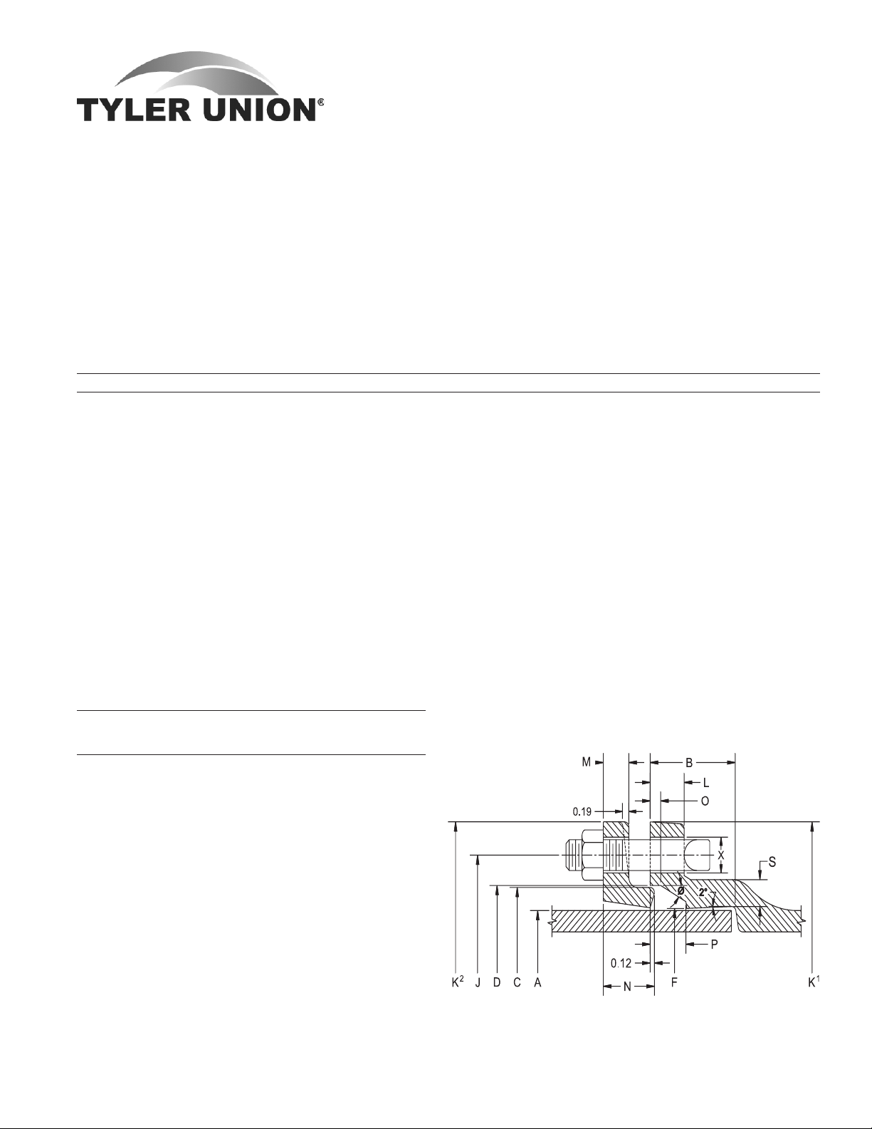
JOINT DIMENSIONS IN INCHES FOR MECHANICAL JOINT FITTINGS
DIMENSIONS IN INCHES
Size A B C D F Ø X J K1 K2 L M N O P S
*2 2.50 2.50 3.39 3.50 2.61 28° ¾ 4.75 6.25 6.25 .75 .62 ... .31 .63 .44
3 3.96 2.50 4.84 4.94 4.06 28° ¾ 6.19 7.69 7.69 .94 .62 1.37 .31 .63 .52
4 4.80 2.50 5.92 6.02 4.90 28° Â 7.50 9.12 9.12 1.00 .75 1.50 .31 .75 .65
6 6.90 2.50 8.02 8.12 7.00 28° Â 9.50 11.12 11.12 1.06 .88 1.63 .31 .75 .70
8 9.05 2.50 10.17 10.27 9.15 28° Â 11.75 13.37 13.37 1.12 1.00 1.75 .31 .75 .75
10 11.10 2.50 12.22 12.34 11.20 28° Â 14.00 15.69 15.62 1.19 1.00 1.75 .31 .75 .80
12 13.20 2.50 14.32 14.44 13.30 28° Â 16.25 17.94 17.88 1.25 1.00 1.75 .31 .75 .85
14 15.30 3.50 16.40 16.54 15.44 28° Â 18.75 20.31 20.25 1.31 1.25 2.00 .31 .75 .89
16 17.40 3.50 18.50 18.64 17.54 28° Â 21.00 22.56 22.50 1.38 1.31 2.06 .31 .75 .97
18 19.50 3.50 20.60 20.74 19.64 28° Â 23.25 24.83 24.75 1.44 1.38 2.13 .31 .75 1.05
20 21.60 3.50 22.70 22.84 21.74 28° Â 25.50 27.08 27.00 1.50 1.44 2.19 .31 .75 1.12
24 25.80 3.50 26.90 27.04 25.94 28° Â 30.00 31.58 31.50 1.62 1.56 2.31 .31 .75 1.22
30 32.00 4.00 33.29 33.46 32.17 20° 1¿ 36.88 39.12 39.12 1.81 2.00 2.75 .38 1.00 1.50
36 38.30 4.00 39.59 39.76 38.47 20° 1¿ 43.75 46.00 46.00 2.00 2.00 2.75 .38 1.00 1.80
42 44.50 4.00 45.79 45.96 44.67 20° 1À 50.62 53.12 53.12 2.00 2.00 2.75 .38 1.00 1.95
48 50.80 4.00 52.09 52.26 50.97 20° 1À 57.50 60.00 60.00 2.00 2.00 2.75 .38 1.00 2.20
* Not included in AWWA C110.
ACCESSORIES AND WEIGHTS
Wt. of Gland, Pipe
Bolt Bolt Bolt Torque Bolts and Barrel
Size No. Size Length Ft/Lbs. Gasket, Lbs. O.D.
*2 2 Á 3 45-60 5 2.50
3 4 Á 3 45-60 7 3.96
4 4 ¾ 3½ 75-90 10 4.80
6 6 ¾ 4 75-90 16 6.90
8 6 ¾ 4 75-90 25 9.05
10 8 ¾ 4 75-90 30 11.10
12 8 ¾ 4 75-90 40 13.20
14 10 ¾ 4½ 75-90 45 15.30
16 12 ¾ 4½ 75-90 55 17.40
18 12 ¾ 4½ 75-90 65 19.50
20 14 ¾ 4½ 75-90 85 21.60
24 16 ¾ 5 75-90 105 25.80
30 20 1 6 100-120 220 32.00
36 24 1 6 100-120 301 38.30
42 28 1¼ 6½ 120-150 389 44.50
48 32 1¼ 6½ 120-150 477 50.80
* Not included in AWWA C110.
ANSI/AWWA C110/A21.10, ANSI/AWWA C111/A21.11
Tyler Utilities Division • 11910 CR 492 • Tyler, Texas 75706 • (800) 527-8478
02/01/08 Union Foundry Company • Box 309 • Anniston, Alabama 36202 • (800) 226-7601 11
14" THRU 48"
GLANDS MAY
BE TAPERED
BENDS
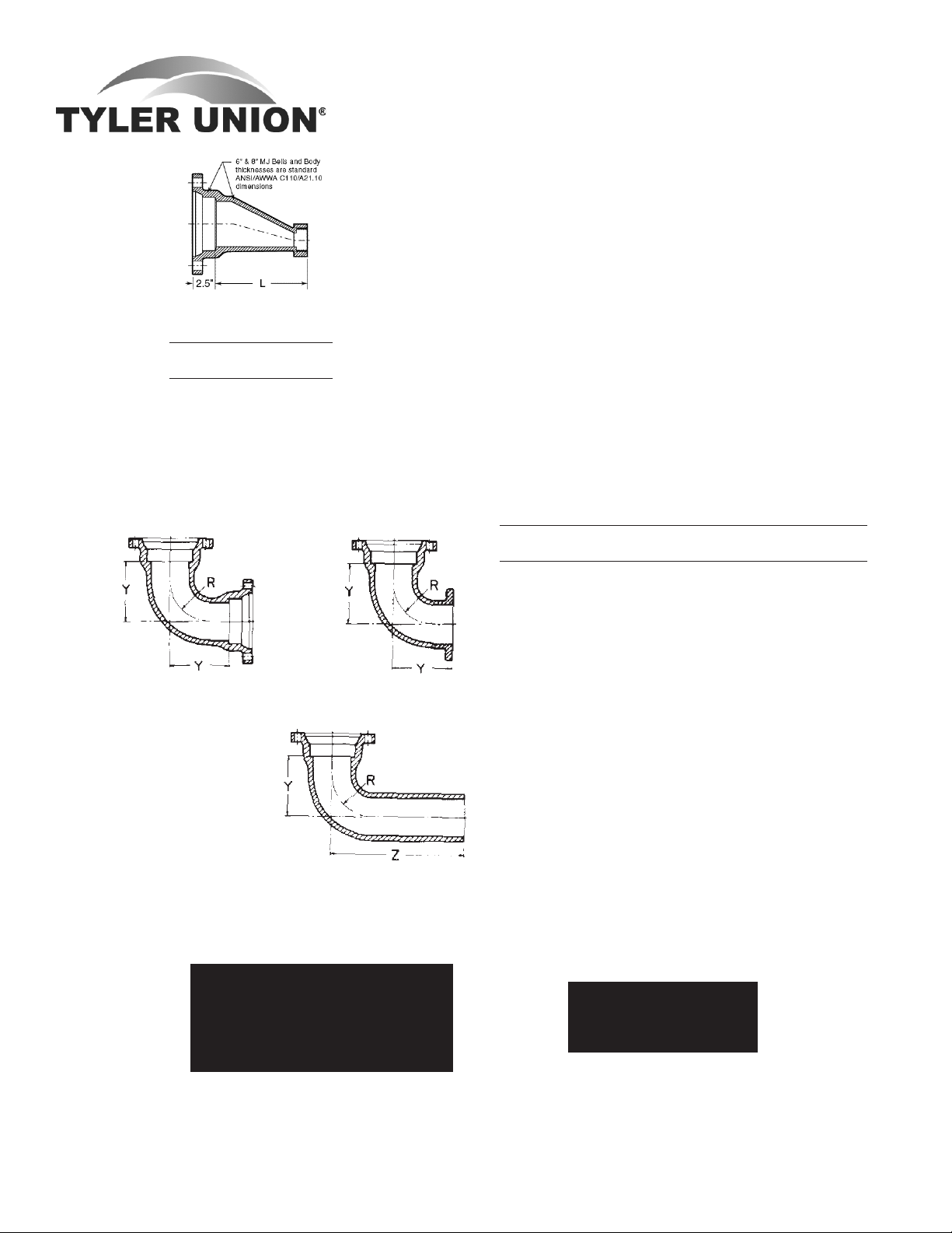
MJ x FIPT ECCENTRIC
REDUCER
Dimensions
Size L Weights
6x2 13 51
8x2 15 71
90° MJ x MJ (1/4)
90° MJ x PE (1/4)
90° MJ x FE (1/4)
DUCTILE IRON C110 FULL BODY
MECHANICAL JOINT FITTINGS
90° Bends (1/4)
Dimensions Weights
Size R Y Z MJxMJ MJxPE MJxFE
*2 2.25 3.25 ... 16 ... ...
3 4.0 5.5 13.5 26 36 ...
4 4.5 6.5 14.5 56 53 51
6 6.0 8.0 16.0 88 80 75
8 7.0 9.0 17.0 123 119 118
10 9.0 11.0 19.0 189 181 168
12 10.0 12.0 20.0 268 252 288
14 11.5 14.0 22.0 380 ... ...
16 12.5 15.0 23.0 552 470 465
18 14.0 16.5 24.5 625 600 577
20 15.5 18.0 26.0 862 775 ...
24 18.5 22.0 30.0 1423 1301 1150
30 21.5 25.0 33.0 1942 1920 ...
36 24.5 28.0 36.0 2629 2310 ...
42 27.5 31.0 3410 ... ...
48 30.5 34.0 4595 ... ...
Mechanical Joint weights
do not include Glands,
Nuts, Bolts and Gaskets.
For sizes not found in this
section check MJ-SSB DI
fittings, pages 1 thru 8.
See Joint Accessories.
ANSI/AWWA C110/A21.10, ANSI/AWWA C111/A21.11
Tyler Utilities Division • 11910 CR 492 • Tyler, Texas 75706 • (800) 527-8478
12 Union Foundry Company • Box 309 • Anniston, Alabama 36202 • (800) 226-7601 02/01/08
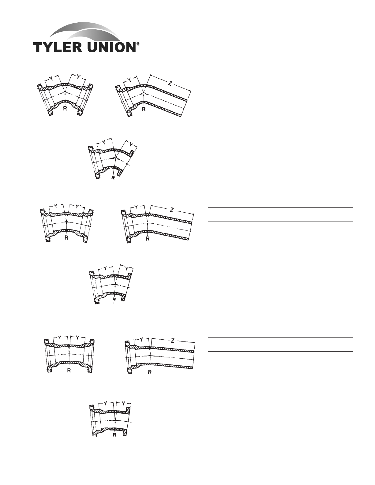
BENDS
45° MJ (1/8)
45° MJ x FE (1/8)
22½° MJ (1/16) 22½° MJ x PE (1/16)
22½° MJ x FE (1/16)
45° MJ x PE (1/8)
DUCTILE IRON C110 FULL BODY
MECHANICAL JOINT FITTINGS
45° Bends (1/8)
Dimensions Weights
Size R Y Z MJ MJxFE* MJxPE
*2 1.96 1.8 ... 16 ... ...
3 3.62 3.0 11.0 30 ... ...
4 4.81 4.0 12.0 53 48 45
6 7.25 5.0 13.0 77 60 69
8 8.44 5.5 13.5 110 107 111
10 10.88 6.5 14.5 172 168 167
12 13.25 7.5 15.5 222 215 218
14 12.06 7.5 15.5 311 ... ...
16 13.25 8.0 16.0 364 360 360
18 14.50 8.5 16.5 531 430 455
20 16.88 9.5 17.5 655 543 664
24 18.12 11.0 19.0 865 1099 825
30 27.75 15.0 23.0 1447 ... 1510
36 35.00 18.0 26.0 2435 ... 1930
42 42.25 21.0 2955 ... ...
48 49.50 24.0 4080 ... ...
* Not included in AWWA C110.
22½° Bends (1/16)
Dimensions Weights
Size R Y Z MJ MJxFE* MJxPE
3 7.56 3.0 11.0 30 ... ...
4 10.06 4.0 12.0 52 ... ...
6 15.06 5.0 13.0 77 71 70
8 17.62 5.5 13.5 110 107 109
10 22.62 6.5 14.5 156 155 163
12 27.62 7.5 15.5 221 215 224
14 25.12 7.5 15.5 300 ... ...
16 27.62 8.0 16.0 391 315 365
18 30.19 8.5 16.5 527 422 455
20 35.19 9.5 17.5 611 ... 575
24 37.69 11.0 19.0 986 800 930
30 57.81 15.0 23.0 1898 ... 1540
36 72.88 18.0 26.0 2372 ... 1970
42 88.00 21.0 3020 ... ...
48 103.06 24.0 4170 ... ...
11¼° Bends (1/32)
Dimensions Weights
Size R Y Z MJ MJxFE* MJxPE
3 15.25 3.0 11.0 30 ... ...
4 20.31 4.0 12.0 52 ... ...
6 30.50 5.0 13.0 65 71 ...
11¼° MJ (1/32)
11¼° MJ x PE (1/32)
8 35.50 5.5 13.5 104 105 ...
10 45.69 6.5 14.5 171 ... ...
12 55.81 7.5 15.5 221 215 ...
14 50.75 7.5 15.5 305 ... ...
16 55.81 8.0 16.0 391 367 ...
18 60.94 8.5 16.5 525 422 ...
20 71.06 9.5 17.5 605 ... ...
24 76.12 11.0 19.0 996 800 972
30 116.75 15.0 23.0 1410 ... 1305
36 147.25 18.0 26.0 2397 ... 2185
11¼° MJ x FE (1/32)
42 177.69 21.0 3035 ... ...
48 208.12 24.0 4190 ... ...
Tyler Utilities Division • 11910 CR 492 • Tyler, Texas 75706 • (800) 527-8478
02/01/08 Union Foundry Company • Box 309 • Anniston, Alabama 36202 • (800) 226-7601 13
ANSI/AWWA C110/A21.10, ANSI/AWWA C111/A21.11
DUCTILE IRON C110 FULL BODY
MECHANICAL JOINT FITTINGS
TEES
MJ TAPPED TEE
Straight Tees and
Reducing on Branch Tees
Bullhead
MJxMJxFE
MJ Tapped Tee (2"Tap)
Dimensions
Size L Max. Tap Weights
3 8 2 40
4 8 2 51
6 8 2 73
8 8 2 104
10 8 2 130
12 8 2 180
Size Dimensions Weights
Run Run Branch X Y Z MJ **MJxPExMJ **MJxMJxFE
*2 2 2 3.25 3.25 ... 21 ... ...
*3 3 2 3.25 3.25 ... 45 ... ...
3 3 3 5.5 5.5 13.5 58 ... ...
*4 4 2 4.8 4.8 14.5 68 ... 49
4 4 3 6.5 6.5 14.5 77 ... ...
4 4 4 6.5 6.5 14.5 78 75 76
4 4 6 8.0 8.0 ... 112 ... ...
*6 6 2 8.0 8.0 ... 78 ... ...
6 6 3 8.0 8.0 16.0 112 ... ...
6 6 4 8.0 8.0 16.0 110 ... 109
6 6 6 8.0 8.0 16.0 119 120 141
6 6 8 9.0 9.0 ... 158 ... ...
8 8 3 9.0 9.0 17.0 155 ... ...
8 8 4 9.0 9.0 17.0 157 ... 150
8 8 6 9.0 9.0 17.0 175 170 182
8 8 8 9.0 9.0 17.0 199 180 194
10 10 4 11.0 11.0 19.0 ... ... 229
10 10 6 11.0 11.0 19.0 258 ... 264
10 10 8 11.0 11.0 19.0 268 ... 245
10 10 10 11.0 11.0 19.0 300 250 ...
12 12 4 12.0 12.0 20.0 318 315 323
12 12 6 12.0 12.0 20.0 325 325 335
12 12 8 12.0 12.0 20.0 335 335 372
12 12 10 12.0 12.0 20.0 392 390 ...
12 12 12 12.0 12.0 20.0 396 396 476
*16 16 4 15.0 15.0 ... 600 ... 575
16 16 6 15.0 15.0 ... 656 ... 605
16 16 8 15.0 15.0 ... 625 ... 615
16 16 10 15.0 15.0 ... 645 ... ...
16 16 12 15.0 15.0 ... 715 ... 651
16 16 16 15.0 15.0 ... 780 ... 730
For sizes not found in this
section check MJ-SSB DI
fittings, pages 1 thru 8.
* Not included in AWWA C110
** Made to order only. Not Returnable
NOTICE: Weights published in this catalog are for shipping purposes only. Actual weights may vary
because some fittings are produced in both foundries. All fittings meet the AWWA standards to which they
are designed.
For weights of specific fittings, please contact Tyler Pipe or Union Foundry Company.
ANSI/AWWA C110/A21.10, ANSI/AWWA C111/A21.11
Tyler Utilities Division • 11910 CR 492 • Tyler, Texas 75706 • (800) 527-8478
14 Union Foundry Company • Box 309 • Anniston, Alabama 36202 • (800) 226-7601 02/01/08
DUCTILE IRON C110 FULL BODY
MECHANICAL JOINT FITTINGS
TEES (Con't)
Straight Tees and
Reducing on Branch Tees
Bullhead
MJxMJxFE
Size Dimensions Weights
Run Run Branch X Y Z MJ **MJxPExMJ **MJxMJxFE
18 18 6 13.0 15.5 ... 710 ... 707
18 18 8 13.0 15.5 ... 674 ... 675
18 18 12 13.0 15.5 ... 749 ... 733
18 18 18 16.5 16.5 ... 945 ... 953
20 20 6 14.0 17.0 ... 849 ... ...
20 20 8 14.0 17.0 ... 892 ... 859
20 20 12 14.0 17.0 ... 896 ... ...
20 20 16 18.0 18.0 ... 1095 ... ...
20 20 20 18.0 18.0 ... 1258 ... 1168
24 24 6 15.0 19.0 ... 1233 ... 1228
24 24 8 15.0 19.0 ... 1234 ... 1242
24 24 12 15.0 19.0 ... 1256 ... 1165
24 24 14 15.0 19.0 ... 1220 ... ...
24 24 16 15.0 19.0 ... 1245 ... ...
24 24 18 22.0 22.0 ... 1735 ... ...
24 24 20 22.0 22.0 ... 1720 ... ...
24 24 24 22.0 22.0 ... 1947 ... 1795
30 30 6 18.0 23.0 ... 2050 ... ...
30 30 8 18.0 23.0 ... 2060 ... ...
30 30 10 18.0 23.0 ... 2075 ... ...
30 30 12 18.0 23.0 ... 2090 .... ...
30 30 16 18.0 23.0 ... 2145 ... ...
30 30 18 18.0 23.0 ... 2170 ... ...
30 30 20 18.0 23.0 ... 2205 ... ...
30 30 24 25.0 25.0 ... 2880 ... ...
30 30 30 25.0 25.0 ... 2275 ... 3080
36 36 6 20.0 26.0 ... 2439 ... 2430
36 36 8 20.0 26.0 ... 2444 ... ...
36 36 10 20.0 26.0 ... 2535 ... ...
36 36 12 20.0 26.0 ... 2541 ... 2550
36 36 14 20.0 26.0 ... 2570 ... ...
36 36 16 20.0 26.0 ... 2585 ... 2450
36 36 18 20.0 26.0 ... 2610 ... ...
36 36 20 20.0 26.0 ... 2635 ... ...
36 36 24 20.0 26.0 ... 2792 ... 2660
36 36 30 28.0 28.0 ... 3545 ... ...
36 36 36 28.0 28.0 ... 3450 ... ...
42 24 42 23.0 30.0 ... 3690 ... ...
42 30 42 31.0 31.0 ... 4650 ... ...
42 36 42 31.0 31.0 ... 4880 ... ...
42 42 42 31.0 31.0 ... 6320 ... ...
48 24 48 26.0 34.0 ... 4995 ... ...
48 30 48 26.0 34.0 ... 5140 ... ...
48 36 48 34.0 34.0 ... 6280 ... ...
48 42 48 34.0 34.0 ... 8130 ... ...
48 48 48 34.0 34.0 ... 8420 ... ...
* Not included in AWWA C110 ** Made to order only. Not Returnable
ANSI/AWWA C110/A21.10, ANSI/AWWA C111/A21.11
Tyler Utilities Division • 11910 CR 492 • Tyler, Texas 75706 • (800) 527-8478
02/01/08 Union Foundry Company • Box 309 • Anniston, Alabama 36202 • (800) 226-7601 15
DUCTILE IRON C110 FULL BODY
MECHANICAL JOINT FITTINGS
WYES/LATERAL
( Not included in AWWA C110.)
Size Dimensions
Run Branch X Z Weights
3 3 10.0 3.0 60
4 4 12.0 3.0 90
6 4 14.5 3.5 130
6 6 14.5 3.5 145
8 4 17.5 4.5 190
8 6 17.5 4.5 205
8 8 17.5 4.5 230
10 6 20.5 5.0 330
10 8 20.5 5.0 310
10 10 20.5 5.5 435
12 8 24.5 5.5 505
12 12 24.5 5.5 490
14 6 27.0 6.0 626
16 16 30.0 6.5 1079
18 8 32.0 7.0 1073
18 10 32.0 7.0 975
18 12 32.0 7.0 1015
18 16 32.0 7.0 1135
18 18 32.0 7.0 1130
20 10 35.0 8.0 1220
20 12 35.0 8.0 1260
20 16 35.0 8.0 1375
20 20 35.0 8.0 1525
24 24 40.5 9.0 2372
30 30 49.0 10.0 3670
For sizes not found in this
section check MJ-SSB DI
fittings, pages 1 thru 8.
CROSSES
ALL MJ
Size Dimensions Weights
Run Branch X Y MJ *MJxFE
6 6 8.0 8.0 160 141
8 4 9.0 9.0 185 ...
8 6 9.0 9.0 205 182
8 8 9.0 9.0 255 245
10 6 11.0 11.0 285 ...
10 8 11.0 11.0 310 ...
10 10 11.0 11.0 380 360
12 6 12.0 12.0 361 367
12 8 12.0 12.0 371 373
12 12 12.0 12.0 486 487
14 8 14.0 14.0 550 ...
14 14 14.0 14.0 779 ...
16 6 15.0 15.0 650 ...
16 8 15.0 15.0 675 655
16 16 15.0 15.0 895 875
18 8 13.0 15.5 775 ...
18 10 13.0 15.5 760 ...
18 12 13.0 15.5 860 ...
18 18 16.5 16.5 1140 ...
20 8 14.0 17.0 951 ...
20 12 14.0 17.0 977 ...
20 16 18.0 18.0 1245 ...
20 20 18.0 18.0 1448 ...
24 8 15.0 19.0 1244 ...
24 12 15.0 19.0 1326 ...
24 16 15.0 19.0 1479 ...
24 20 22.0 22.0 1965 ...
24 24 22.0 22.0 2192 ...
30 6 18.0 23.0 2085 ...
30 12 18.0 23.0 2165 ...
30 24 25.0 25.0 3180 ...
30 30 25.0 25.0 3640 ...
36 36 28.0 28.0 4370 ...
* Not included in AWWA C110.
*MJ x MJ x FE x FE
ANSI/AWWA C110/A21.10, ANSI/AWWA C111/A21.11
Tyler Utilities Division • 11910 CR 492 • Tyler, Texas 75706 • (800) 527-8478
16 Union Foundry Company • Box 309 • Anniston, Alabama 36202 • (800) 226-7601 02/01/08

DUCTILE IRON C110 FULL BODY
MECHANICAL JOINT FITTINGS
REDUCERS
MJ Reducer
MJ Small End Bell Reducer
MJ Large End Bell Reducer
Plain End-Plain End Reducer
FExMJ Reducer
Laying Lengths (L) Weights
Size MJ MJ-SEB MJ-LEB PExPE FExMJ MJxFE MJ MJ-SEB MJ-LEB PExPE FExMJ MJxFE
* 3x2 6 14 14 ... ... ... 24 24 24 ... ... ...
* 4x2 7 15 15 ... ... ... 31 30 31 ... ... ...
4x3 7 15 15 23 7 7 37 38 37 34 34 35
* 6x2 9 17 17 ... ... ... 46 43 47 ... ... ...
6x3 9 17 17 ... ... 9 55 50 55 ... ... 50
6x4 9 17 17 25 9 9 56 60 59 57 53 62
8x3 11 19 19 ... ... ... 84 77 70 ... ... ...
8x4 11 19 19 ... 11 11 84 82 84 ... 73 75
8x6 11 19 19 27 11 11 94 90 93 96 84 80
10x6 12 20 20 ... 12 12 115 116 117 ... 100 105
10x8 12 20 20 28 12 12 142 135 130 135 130 130
12x4 14 22 22 ... ... ... 139 131 ... ... ... ...
12x6 14 22 22 ... 14 12 148 150 153 ... 145 130
12x8 14 22 22 30 14 12 173 168 165 168 170 175
12x10 14 22 22 30 14 12 194 190 178 185 188 190
14x6 ... ... ... ... ... 16 ... ... ... ... ... 195
14x8 ... ... ... ... ... 16 ... ... ... ... ... 215
14x12 ... ... ... ... ... 16 ... ... ... ... ... 270
16x6 18 ... ... ... ... ... 250 ... ... ... ... ...
16x8 18 26 ... ... ... ... 288 248 ... ... ... ...
16x10 18 ... ... ... ... ... 300 ... ... ... ... ...
16x12 18 26 26 ... 18 18 330 304 325 ... 305 325
16x14 18 ... ... ... ... ... 370 ... ... ... ... ...
18x8 19 ... ... ... ... 19 320 ... ... ... ... 300
18x10 19 ... ... ... ... ... 388 ... ... ... ... ...
18x12 19 27 ... ... ... 19 380 355 ... ... ... 405
18x14 19 ... ... ... ... ... 450 ... ... ... ... ...
18x16 19 ... ... ... ... 19 476 ... ... ... ... 445
20x10 20 ... ... ... ... ... 410 ... ... ... ... ...
20x12 20 28 ... ... ... ... 515 420 ... ... ... ...
20x16 20 28 28 ... ... 20 578 525 510 ... ... 510
20x18 20 ... ... ... ... ... 575 ... ... ... ... ...
24x12 24 32 ... ... ... 24 610 570 ... ... ... 455
24x16 24 32 32 ... ... ... 705 665 753 ... ... ...
24x18 24 32 ... ... ... ... 789 720 ... ... ... ...
24x20 24 32 32 ... ... ... 815 775 804 ... ... ...
*30x16 30 38 ... 46 ... ... 1150 1040 ... 1015 ... ...
30x18 30 38 ... 46 ... ... 1160 1050 ... 1025 ... ...
30x20 30 38 ... 46 ... ... 1225 1120 ... 1090 ... ...
30x24 30 38 38 46 ... ... 1360 1255 1320 1215 ... ...
36x20 36 ... 44 ... ... ... 1495 ... 1466 ... ... ...
36x24 36 ... 44 52 ... ... 1580 ... 1535 1389 ... ...
36x30 36 44 ... 52 ... ... 1919 1721 ... 1585 ... ...
42x24 42 ... ... ... ... ... 2060 ... ... ... ... ...
42x30 42 ... ... ... ... ... 2370 ... ... ... ... ...
42x36 42 ... ... ... ... ... 2695 ... ... ... ... ...
48x30 48 ... ... ... ... ... 3005 ... ... ... ... ...
48x36 48 ... ... ... ... ... 3370 ... ... ... ... ...
48x42 48 ... ... ... ... ... 3750 ... ... ... ... ...
* Not included in AWWA C110
MJxFE Reducer
ANSI/AWWA C110/A21.10, ANSI/AWWA C111/A21.11
Tyler Utilities Division • 11910 CR 492 • Tyler, Texas 75706 • (800) 527-8478
02/01/08 Union Foundry Company • Box 309 • Anniston, Alabama 36202 • (800) 226-7601 17

SOLID SLEEVES
DUCTILE IRON C110 FULL BODY
MECHANICAL JOINT FITTINGS
Standard
Pipe Short Long
Size O.D. L Weight L Weight
*2 2.50 8.0 13 12 18
3 3.96 7.5 ... 12 36
4 4.80 7.5 35 12 47
6 6.90 7.5 45 12 65
8 9.05 7.5 65 12 90
10 11.10 7.5 85 12 115
12 13.20 7.5 120 12 136
16 17.40 9.5 206 15 281
18 19.50 9.5 246 15 362
20 21.60 9.5 275 15 404
24 25.80 9.5 360 15 540
30 32.00 15.0 745 24 1085
36 38.30 15.0 1047 24 1502
42 44.50 ... ... 24 1550
48 50.8 ... ... 24 1940
* Not included in AWWA C110
* Dual Purpose †
Pipe Short Long
Size O.D. L Weight L Weight
4 4.80/5.00 7.5 33 12 44
6 6.90/7.10 7.5 46 12 63
8 9.05/9.30 7.5 65 12 88
10 11.10/11.40 ... ... 12 111
†12 13.20/13.50 ... ... 12 221
†16 17.40/17.80 ... ... 15 385
All Sizes Use MJ Dual Purpose Gland
* Not included in AWWA C110
† 12" & 16" are sold assembled
NOTE: Sizes 4-10" use standard MJ Gaskets;
* MJ x PE DUAL-PURPOSE CUTTING-IN SLEEVE
With Dual-Purpose Accessories
(NOTES: Gland with cup-joint set screws available at extra cost
when specified. NOT FOR RESTRAINT.)
Currently, Tyler and Union Dual Purpose Glands are NOT
interchangeable.
Cutting-In
Sleeve & Gland
Weight
For Use Gland Gland
Size On Pipe O.D. L L1 D Only & Sleeve
4 4.80 - 5.00 12 8 4.80 6.0 72
6 6.90 - 7.10 12 8 6.90 10.0 94
8 9.05 - 9.30 12 8 9.05 16.0 122
10 11.10 - 11.40 12 8 11.10 25.0 175
12 13.20 - 13.50 12 8 13.20 30.0 235
* Not included in AWWA C110.
12" and 16" require special duo gaskets.
ADAPTERS
MJ x FE
Dimensions
Size L Weights
3 8 30
4 8 42
6 8 62
8 8 88
10 8 120
12 8 150
16 8 257
18 8 324
20 8 365
24 8 528
30 10 760
36 10 1070
ANSI/AWWA C110/A21.10, ANSI/AWWA C111/A21.11
Tyler Utilities Division • 11910 CR 492 • Tyler, Texas 75706 • (800) 527-8478
18 Union Foundry Company • Box 309 • Anniston, Alabama 36202 • (800) 226-7601 02/01/08

DUCTILE IRON C110 FULL BODY
MECHANICAL JOINT FITTINGS
PLUGS
Solid or Tapped
Weight
Size Tap Solid Tapped
*2 2 5 5
3 2 9 9
4 2 13 14
6 2 15 15
8 2 45 45
10 2 66 66
12 2 79 79
14 2 120 120
16 2 147 147
†18 2 192 190
†20 2 220 219
†24 2 338 338
†30 2 660 660
†36 2 838 838
42 .. 1180 ...
48 .. 1455 ...
† Dished – Not flat as shown.
* Not included in
AWWA C110.
CAPS
Solid or Tapped
Weight
Size Tap Solid Tapped
*2 2 6 ...
3 2 10 10
4 2 18 13
6 2 34 30
8 2 46 45
10 2 58 54
12 2 86 80
16 2 178 175
†18 2 215 215
†20 2 250 249
†24 2 370 370
†30 2 680 680
†36 2 850 850
42 .. 1180 ...
48 .. 1595 ...
† Dished – Not flat as shown.
* Not included in
AWWA C110.
OFFSETS
MJ x MJ MJ x PE
Dimensions Weights
Size D L1 L MJxMJ MJxPE
4 6 19 27 ... 82
4 12 22 30 85 80
4 18 30 38 105 ...
* 4 24 26 34 126 125
6 6 20 28 114 105
6 12 26 34 148 143
6 18 33 41 188 176
* 6 24 24 32 182 160
8 6 21 29 177 155
8 12 28 36 231 195
8 18 35 43 287 282
* 8 24 36 44 280 285
10 12 30 38 347 280
10 18 38 46 340 340
10 24 38 46 420 ...
12 12 37 45 420 420
12 18 48 56 520 520
*12 24 48 56 649 630
16 12 40 48 715 ...
16 18 50 58 850 830
*20 12 40 48 1025 ...
*20 18 48 60 1362 ...
* Not included in AWWA C110.
TYTON® Plug**
Solid or Tapped
Size Tap T Weight*
4 2 .60 18
6 2 .65 25
8 2 .70 46
10 2 .75 70
12 2 .75 95
* Weights do not include accessories
** Not included in AWWA C110.
TYTON® is a registured trademark
of U.S. Pipe and Foundry Company.
Tyler Utilities Division • 11910 CR 492 • Tyler, Texas 75706 • (800) 527-8478
02/01/08 Union Foundry Company • Box 309 • Anniston, Alabama 36202 • (800) 226-7601 19
Solid Tapped
Push-In Plug with Ears
(To be used with all push-in
pipe and fittings)
Size Tap Weight
14 2.0 101
16 2.0 137
18 2.0 177
†20 2.0 239
†24 2.0 311
† Dished - Not flat as shown
NOTE: Blocking still required–
ears for assembly only.
ANSI/AWWA C110/A21.10, ANSI/AWWA C111/A21.11

*RETAINER GLAND ASSEMBLY
See Installations Instructions ........................................................ Page 50
Pressure Gland Pipe O.D. D.I. Pipe No of Size of
Rating, O.D. O.D. Wall Set Set Gland Weight
Size psi B A Class Screws Screws Weight w/Acces.
3 350 7.69 3.96 50-56 4 Á x2 4 8
4 350 9.12 4.80 50-56 4 Á x2 5 11
6 350 11.12 6.90 50-56 6 Á x2 9 16
8 250 13.37 9.05 50-56 9 Á x2 13 21
10 250 15.62 11.10 50-56 12 Á x2 17 26
12 150 17.88 13.20 50-56 16 Á x2 20 28
14 250 20.25 15.30 53-56 20 Á x2½ 44 55
16 200 22.50 17.40 53-56 24 Á x2½ 54 64
18 200 24.75 19.50 53-56 24 Á x2½ 62 72
20 200 27.00 21.60 53-56 28 Á x3 76 91
24 150 31.50 25.80 53-56 32 Á x3 103 118
* Not included in AWWA C110
DUCTILE IRON C110 FULL BODY
MECHANICAL JOINT FITTINGS
Pipe Wall Thickness:
Sizes 3"-12" are recommended for ductile
iron pipe class 50 thru 56. Sizes 14" thru
24" are recommended for ductile iron pipe
class 53 thru 56.
DUCTILE IRON RETAINER
GLANDS
Mechanical Joint Retainer Glands are
designed to provide a method for restraining mechanical joint pipe and fittings
and other standardized mechanical joints
against possible joint separation, rupture
or blow-out caused by internal water pressure.
The set screws are square-headed
with Type C knurled cup points, and are
shipped already assembled in the Glands.
They are manufactured of 4140 grade
alloy steel, and are heat treated to a Rockwall “C” 45/53 case hardness. Tee-head
bolts and gaskets are not included, but
may be ordered separately. Recommended torque for set screws is 75 foot pounds,
and set screws on opposite sides of the
glands should be tightened alternately.
Tee-head bolt hole size and spacing are equal to MJ Glands as shown in
AWWA C-111. Standard mechanical Joint
gaskets as shown in C-111 should be
used.
TEES
MJ x MJ x Swivel
Dimensions
Size X Y Weight
6 8.0 10.5 150
8x6 9.0 11.5 199
8 9.0 11.5 210
10x6 11.0 13.5 267
12x6 12.0 14.5 346
16x6 15.0 17.5 619
16x8 15.0 17.5 649
30x6 18.0 24.5 2070
All weights shown include the Swivel Gland
ANSI/AWWA C110/A21.10, ANSI/AWWA C111/A21.11
Tyler Utilities Division • 11910 CR 492 • Tyler, Texas 75706 • (800) 527-8478
20 Union Foundry Company • Box 309 • Anniston, Alabama 36202 • (800) 226-7601 02/01/08
MJ GLAND
Gland Weight
Size Wt. Pack Gland Only
2 5 3
3 7 4
4 10 6
6 16 10
8 25 16
10 30 19
12 40 26
14 45 34
16 55 54
18 65 52
20 85 73
24 105 91
30 220 90
36 301 127

ADAPTERS
ELLS
Swivel x Solid Adapter
Size by Wall
Laying Length Thickness Weight*
4x13 .52 52
6x12 .55 84
6x18 .55 91
6x24 .55 105
6x36 .55 156
8x13 .60 126
12x13 .75 186
* Weights with Gland.
DUCTILE IRON C110 FULL BODY
MECHANICAL JOINT ELLS, ADAPTERS
AND GLANDS
For Valve and Hydrant Connections
Other Swivel Hydrant
Fittings, Pages 3, 4 and 5.
*90° Swivel x Swivel Ell
(Not Included In AWWA C110)
Wall Dimensions
Size Thickness A B C D E F R *Weight
6 .55 10.5 15.5 7.10 11.12 6.90 8.02 6.0 106
8 .60 11.5 16.5 9.20 13.37 9.05 10.17 7.0 156
* With 2 Swivel Glands
SWIVEL GLAND ASSEMBLY
Used with swivel fittings, the TYLER Swivel Gland, with its rotating feature, permits the installer to meet any grade requirements regardless of bolt-hole alignment. In addition, the system permits stiff connections without braces, blocking or strapping.
Swivel Glands**
Size Weight
12 30
** Not included in
AWWA C110.
NOTE: When ordering glands
separately,
(1) Specify TYLER UPCode
Number,
(2) Description, and
(3) Size of fitting to be joined.
ANSI/AWWA C110/A21.10, ANSI/AWWA C111/A21.11
Tyler Utilities Division • 11910 CR 492 • Tyler, Texas 75706 • (800) 527-8478
02/01/08 Union Foundry Company • Box 309 • Anniston, Alabama 36202 • (800) 226-7601 21
UNION-TITE DUCTILE IRON
C153 COMPACT FITTINGS
SAMPLE SPECIFICATIONS
4"through24"Push-OnJointDuctileIronFittingsshallbeproducedinaccordancewithallapplicabletermsandprovisions
ofANSI/AWWAC153/A21.53.Fittingsarecement-linedandseal-coatedinaccordancewithANSI/AWWAC104/A21.4.Joints
shallbeinaccordancewithANSI/AWWAC111/A21.11withbellsocketsdesignedtoreceivepressurepipeO.D.'sasspecified
inANSI/AWWAC151/A21.51andAWWAC900TABLE2.Theworkingpressureratingshallbe350PSI,exceptforwyesand
flanged-branchfittings.NOTE:FittingsareCEMENT-LINEDandsealcoatedinaccordancewithANSI/AWWAC104/A21.4,also
availablebareorepoxycoated.Doublecementlinedavailableinnon-domesticonly.Allcoatedfittingsmeetrequirementsof
NSF-61.
Thicknessesanddimensionsofbellsocketsandgasketsshallbeinaccordancewiththemanufacturer'sdesign.Rubberrings
shallbefurnishedbythemanufacturer.Workingpressuresapplytofittingsonlyanddonotapplytorestraininglugsorexternal
restrainingdevices.
NOTE: Restraining lugs are provided on sizes 4" through 12" ONLy.
NOTE - EXCEPTIONS: Union-Tite Fittings with flanged branches are rated for water pressure of 250 PSI.
ADVANTAGESANDFEATURES
• Push-ongasketjointusesTYTON
®
or SURE 350® STOPgaskets
• ForusewithDuctileIronpipe,C-900plasticpipe,and4-12"pressureratedIPSdiameterplasticpipe
usingtransitiongaskets
• Deepstabjointdesignaccommodatestaperonplasticpipes
• SlipjointinstallationeliminatesT-boltsandnuts:MJglandsnotneeded
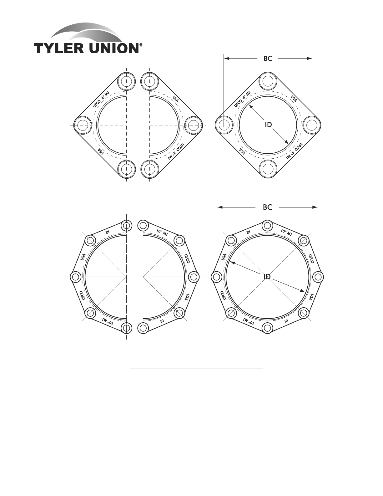
BELL DIMENSIONS IN INCHES FOR UNION-TITE FITTINGS
Pipe
Size A B B.C. C D E
4 5.04 6.38 7.88 4.16 2.25 .35
6 7.14 8.52 10.50 4.29 2.25 .37
8 9.32 10.90 12.88 4.78 2.25 .39
10 11.37 12.91 14.69 4.98 2.25 .41
12 13.47 15.12 17.19 4.98 2.25 .43
14 15.64 18.12 ... 5.40 2.25 .51
16 17.74 20.32 ... 5.40 2.25 .52
18 19.83 22.52 ... 5.40 2.25 .59
20 21.94 24.29 ... 5.40 2.25 .60
24 26.14 29.14 ... 5.65 2.50 .62
TYTON®andFIELD-LOK®areregisteredtrademarksofU.S.PipeandFoundryCompany.
Maximumdeflectionis5°.
TylerUtilitiesDivision•11910CR492•Tyler,Texas75706•(800)527-8478
22 UnionFoundryCompany•Box309•Anniston,Alabama36202•(800)226-7601 02/01/08

UNION-TITE DUCTILE IRON
C153 COMPACT FITTINGS
BENDS
90° (1/4) UT Bends 45° (1/8) UT Bends 22½° (1/16) UT Bends 11¼° (1/32) UT Bends
Dimensions Dimensions Dimensions Dimensions
Size T A R Weight A R Weight A R Weight A R Weight
4 .35 4.5 3.87 24 2.0 3.31 26 1.50 4.38 18 1.25 6.77 18
6 .37 6.0 5.37 51 3.0 5.72 42 2.25 8.16 39 1.50 9.38 40
8 .39 7.0 6.37 80 3.5 6.93 66 2.50 9.40 64 1.75 11.48 60
10 .41 9.0 8.36 121 4.5 9.34 101 3.00 13.17 67 2.00 13.95 77
12 .43 10.0 9.36 151 5.5 11.75 128 3.50 14.42 111 2.25 16.50 94
14 .51 12.0 10.98 254 5.5 10.85 143 3.75 13.82 162 2.60 14.26 113
16 .52 13.0 12.00 328 6.0 12.02 225 4.00 14.97 195 2.60 15.23 172
18 .59 15.5 14.00 482 6.5 12.36 209 7.50 30.19 209 3.00 60.94 209
20 .60 17.0 15.50 340 7.0 13.59 397 8.50 35.19 414 3.50 71.07 265
24 .62 17.0 15.59 674 7.5 14.69 492 9.00 37.69 596 ... ... ...
90° (1/4) 45° (1/8) 22½° (1/16) 11¼° (1/32)
UT x Flange Bends UT x Flange Bends UT x Flange Bends UT x Flange Bends
Dimensions Dimensions Dimensions Dimensions
Size T A B R Weight A B R Weight A B R Weight A B R Weight
4 .35 4.5 6.5 3.87 31 2.0 4.0 3.31 21 1.50 3.5 4.38 25 1.25 3.30 6.77 24
6 .37 6.0 7.0 5.37 49 3.0 5.0 5.72 42 2.25 4.3 8.16 44 1.50 3.50 9.38 30
8 .39 7.0 9.0 6.37 74 3.5 5.5 6.93 60 2.50 4.5 9.40 64 1.75 3.75 11.48 61
10 .41 9.0 10.0 8.36 130 4.5 6.5 9.34 93 3.00 5.3 13.17 90 2.00 4.00 13.95 80
12 .43 10.0 12.0 9.36 158 5.5 7.5 11.75 122 3.50 5.5 14.42 112 2.25 4.30 16.50 94
14 .51 12.0 15.5 10.98 231 5.5 8.5 10.85 162 3.75 6.8 13.82 174 2.60 5.75 14.26 170
16 .52 13.0 16.5 12.00 233 6.0 9.5 12.02 275 4.00 7.5 14.97 228 2.60 6.10 15.23 228
Tyler Utilities Division • 11910 CR 492 • Tyler, Texas 75706 • (800) 527-8478
02/01/08 Union Foundry Company • Box 309 • Anniston, Alabama 36202 • (800) 226-7601 23

UNION-TITE DUCTILE IRON
C153 COMPACT FITTINGS
BENDS
90° (1/4) 45° (1/8) 22½° (1/16) 11¼° (1/32)
UT x PE Bends UT x PE Bends UT x PE Bends UT x PE Bends
Dimensions Dimensions Dimensions Dimensions
Size T A B R Weight A B R Weight A B R Weight A B R
Weight
4 .35 4.5 10.5 3.87 35 2.0 8.0 3.31 21 ... ... ... .. ... ... ... ..
6 .37 6.0 12.0 5.37 70 3.0 9.0 5.72 38 2.25 8.08 8.16 35 1.50 7.30 9.38 36
8 .39 ... ... ... .. 3.5 9.5 6.93 60 2.50 8.34 9.40 57 1.75 7.55 11.48 55
TEES
UT x UT x PE Tees
Size Dimensions
Run Branch T T1 H J3 Weight
6 6 .37 .37 6.0 11.5 60
8 6 .39 .37 6.0 12.5 80
12 6 .43 .37 7.0 15.5 140
Tyler Utilities Division • 11910 CR 492 • Tyler, Texas 75706 • (800) 527-8478
24 Union Foundry Company • Box 309 • Anniston, Alabama 36202 • (800) 226-7601 02/01/08

UNION-TITE DUCTILE IRON
C153 COMPACT FITTINGS
TEES
UT x UT Tees UT x Flange Tees UT x Swivel Tees
Dimensions Weights
Size T T1 H J1 J2 J3 UT x UT UT xFlange UT x Swivel
4 .35 .35 4.5 4.5 6.5 ... 44 45 ...
6x4 .37 .35 5.0 6.0 8.0 ... 68 56 ...
6 .37 .37 6.0 6.0 8.0 9.5 69 71 65
8x4 .39 .35 5.0 7.0 9.0 ... 73 89 ...
8x6 .39 .37 6.0 7.0 9.0 10.5 96 101 100
8 .39 .39 7.0 7.0 9.0 10.5 116 117 110
10x4 .41 .35 6.0 9.0 11.0 ... 102 115 ...
10x6 .41 .37 7.0 9.0 11.0 12.5 113 128 130
10x8 .41 .39 8.0 9.0 11.0 12.5 145 145 156
10 .41 .41 9.0 9.0 11.0 ... 155 158 ...
12x4 .43 .35 6.0 10.0 12.0 ... 119 138 ...
12x6 .43 .37 7.0 10.0 12.0 13.5 141 148 162
12x8 .43 .39 8.0 10.0 12.0 13.5 177 170 158
12x10 .43 .41 9.0 10.0 12.0 ... 160 162 ...
12 .43 .43 10.0 10.0 12.0 ... 217 183 ...
14x6 .51 .44 6.5 10.5 12.5 14.0 176 212 202
14x10 .51 .46 8.5 10.5 12.5 ... 195 246 ...
14x12 .51 .47 9.5 10.5 12.5 ... 196 296 ...
14 .51 .51 10.5 10.5 14.0 ... 209 321 ...
16x6 .52 .45 6.5 11.5 13.5 15.0 266 160 229
16x8 .52 .46 7.5 11.5 13.5 15.0 292 270 292
16x10 .52 .47 8.5 11.5 13.5 ... 232 330 ...
16x12 .52 .48 9.5 11.5 13.5 ... 239 321 ...
16x14 .52 .51 10.5 11.5 15.0 ... 349 342 ...
16 .52 .52 11.5 11.5 15.0 ... 261 355 ...
18x6 .59 .44 6.5 12.5 14.5 16.13 348 301 348
18x8 .59 .45 7.5 12.5 14.5 16.13 325 319 324
18x10 .59 .47 8.5 12.5 14.5 ... 344 337 ...
18x14 .59 .56 10.5 12.5 16.0 ... 342 393 ...
18x16 .59 .57 11.5 12.5 16.0 ... 362 420 ...
20x6 .60 .44 7.0 14.0 16.0 17.5 355 341 400
20x10 .60 .47 9.0 14.0 16.0 ... 369 420 ...
20x14 .60 .56 11.0 14.0 17.5 ... 484 474 ...
20x16 .60 .57 12.0 14.0 17.5 ... 610 498 ...
20x18 .60 .59 13.0 14.0 17.5 ... 539 ... ...
24x6 .62 .44 7.0 16.0 18.0 19.5 385 512 525
24x10 .62 .47 9.0 16.0 18.0 ... 478 468 ...
24x12 .62 .49 10.0 16.0 18.0 ... 663 503 ...
24x14 .62 .56 11.0 16.0 19.5 ... 542 531 ...
24x16 .62 .57 12.0 16.0 19.5 ... 566 555 ...
24x18 .62 .59 13.0 16.0 ... ... 593 ...
24x20 .62 .60 15.0 17.0 ... ... 628 ... ...
24 .62 .62 17.0 17.0 ... ... 884 ... ...
Tyler Utilities Division • 11910 CR 492 • Tyler, Texas 75706 • (800) 527-8478
02/01/08 Union Foundry Company • Box 309 • Anniston, Alabama 36202 • (800) 226-7601 25

REDUCERS
UT x UT Reducers UT x Flange Reducers
Dimensions Weights
Size T T1 L G UT x UT UT xFlange
6x4 .37 .35 4.0 6.0 32 32
8x4 .39 .35 5.0 7.0 46 46
8x6 .39 .37 4.0 6.0 49 47
10x4 .41 .35 7.0 9.0 47 55
10x6 .41 .37 5.0 7.0 47 59
10x8 .41 .39 4.0 6.0 53 61
12x4 .43 .35 9.0 11.0 74 78
12x6 .43 .37 7.0 9.0 58 75
12x8 .43 .39 5.0 7.0 74 74
12x10 .43 .41 4.0 6.0 82 95
14x6 .51 .44 9.0 11.0 84 121
14x8 .51 .45 7.0 9.0 85 128
14x10 .51 .46 5.0 7.0 87 127
14x12 .51 .47 4.0 6.0 104 144
16x6 .52 .45 11.0 13.0 94 133
16x8 .52 .46 9.0 11.0 104 141
16x10 .52 .47 7.0 9.0 130 158
16x12 .52 .48 5.0 7.0 152 172
16x14 .52 .51 4.0 6.0 139 196
18x8 .59 .45 14.0 16.0 142 157
18x10 .59 .47 12.0 14.0 151 175
18x12 .59 .49 10.0 12.0 167 215
18x14 .59 .56 8.0 11.5 217 234
18x16 .59 .57 7.0 10.5 202 246
20x10 .60 .47 14.0 16.0 180 234
20x12 .60 .49 12.0 ... 205 ...
20x14 .60 .56 10.0 13.5 233 249
20x16 .60 .57 8.0 11.5 250 272
20x18 .60 .59 7.0 ... 248 ...
24x12 .62 .49 16.0 18.0 246 262
24x14 .62 .56 14.0 17.5 281 315
24x16 .62 .57 12.0 15.5 380 328
24x18 .62 .59 10.0 ... 390 ...
24x20 .62 .60 8.0 ... 421 ...
UNION-TITE DUCTILE IRON
C153 COMPACT FITTINGS
TAPPED TEE/CROSS
UT x Tapped Tee/Crosses
Dimensions
Size T Max Tap L Weight
4 .35 3.0 6.0 27
6 .37 3.5 6.0 38
8 .39 3.5 6.0 59
10 .41 3.5 6.0 72
12 .43 3.5 6.0 92
CAPS AND PLUGS
Solid Cap Solid Plug
UT x Flange Adaptor
Dimensions
Size T L Weight
4 .35 6.0 28
6 .37 6.0 36
8 .39 6.0 54
10 .41 6.0 71
12 .43 6.0 102
14 .51 7.0 113
16 .52 7.0 115
20 .60 6.0 295
Tyler Utilities Division • 11910 CR 492 • Tyler, Texas 75706 • (800) 527-8478
26 Union Foundry Company • Box 309 • Anniston, Alabama 36202 • (800) 226-7601 02/01/08
2" Tapt Cap 2" Tapt Plug
UT Caps and Plugs*
Dimensions Weights
Size T1 T2 L Cap Plug
4 .48 .50 5.25 15 8
6 .48 .50 5.25 20 23
8 .51 .53 5.25 35 32
10 .53 .56 5.25 50 38
12 .55 .62 5.25 75 49
*Restraining lugs (ears) available.

UNION-TITE DUCTILE IRON
C153 COMPACT FITTINGS
WYES CROSSES
UT Wyes
Dimensions
Size T T1 P N Weights
8x4 .39 .35 13.5 .0 89
10x4 .41 .35 15.0 .0 141
10x6 .41 .37 16.0 1.0 151
10x8 .41 .39 17.0 2.5 175
10 .41 .41 18.0 4.0 200
12x4 .43 .35 16.5 .0 178
12x6 .43 .37 18.5 1.5 201
12x8 .43 .39 18.5 1.5 224
12x10 .43 .41 20.0 3.0 240
12 .43 .43 20.0 5.0 289
14x6 .51 .44 19.5 .0 236
14x8 .51 .45 21.0 1.5 255
14x10 .51 .46 22.5 3.0 325
14 .51 .51 25.0 6.0 475
16x6 .52 .45 21.0 .0 281
16x8 .52 .46 22.5 0.5 304
16x12 .52 .48 25.0 3.5 346
16 .52 .52 28.0 6.5 380
TYTON® GASKETS
TYTON® JOINT IPS Transition and Regular Gasket
Dimensions
Transition (IPS) Regular (Ductile)
Size A B(±1%) B* C
4 5.74 4.18 4.68 1.00
6 7.86 6.31 6.73 1.10
8 10.15 8.32 8.85 1.29
10 12.10 10.30 10.87 1.36
12 14.31 12.70 12.95 1.45
TYTON® is a registered trademark of
U.S. Pipe and Foundry Company.
UT Crosses
Dimensions
Size T1 H J Weights
6 .37 6.0 6.0 88
8x6 .37 6.0 7.0 117
8 .39 7.0 7.0 156
10x4 .35 6.0 9.0 116
12x8 .39 8.0 10.0 240
12 .43 10.0 10.0 241
14x6 .44 6.5 10.5 189
14x8 .45 7.5 10.5 204
14x10 .46 8.5 10.5 222
14x12 .47 9.5 10.5 239
14 .51 10.5 10.5 270
16x6 .45 6.5 11.5 234
16x8 .46 7.5 11.5 323
16x10 .47 8.5 11.5 268
16x12 .48 9.5 11.5 274
16x14 .51 10.5 11.5 322
16 .52 11.5 11.5 317
NOTICE: Weights published in this
catalog are for shipping purposes only.
Actual weights may vary because some
fittings are produced in both foundries.
All fittings are made in the USA and meet
the AWWA standards to which they are
designed.
For weights of specific fittings, please
contact Tyler Pipe or Union Foundry
Company.
Tyler Utilities Division • 11910 CR 492 • Tyler, Texas 75706 • (800) 527-8478
02/01/08 Union Foundry Company • Box 309 • Anniston, Alabama 36202 • (800) 226-7601 27

DUCTILE IRON C110
FLANGED FITTINGS
Sizes 3" thru 12" UL Listed for Fire Main Equipment
SAMPLE SPECIFICATION
Flanged Fittings, 2" through 48" shall be manufactured of Ductile Iron in accordance with all applicable terms and provisions of
standards ANSI/AWWA C110/A21.10 (current revisions). Flange surface shall be faced and drilled in accordance with ANSI Class
125 B16.1. All Ductile Iron Flanged Fittings shall be rated for water pressure of 250 PSI. Flanged ductile-iron fittings in 24-in. (610
mm) and smaller sizes may be rated for 350 psi (2,413 kPa) with the use of special gaskets. NOTE: Fittings are CEMENT-LINED
and seal coated in accordance with ANSI/AWWA C104/A21.4, also available prime coated, bare or epoxy coated. All coated fittings
meet requirements of NSF-61. Interiors shall be lined and seal coated in accordance with ANSI/AWWA C104/A21.04, “Cement-
mortor Lining for Ductile Iron Pipe and Fittings for Water” unless otherwise specified.
FLANGE DETAILS
Nominal Dia. of Flange
Pipe Size Flange Bolt Thickness Bolt Hole Number Bolt Dia.
Inch O.D. Circle T Diameter of Bolts and Lengths
2 6 4.75 .62 .75 4 Á x 2¼
3 7.5 6 .75 .75 4 Á x 2½
4 9 7.5 .94 .75 8 Á x 3
6 11 9.5 1.00 .875 8 ¾ x 3½
8 13.5 11.75 1.12 .875 8 ¾ x 3½
10 16 14.25 1.19 1.00 12 Â x 4
12 19 17 1.25 1.00 12 Â x 4
14 21 18.75 1.38 1.125 12 1 x 4½
16 23.5 21.25 1.44 1.125 16 1 x 4½
18 25 22.75 1.56 1.25 16 1¿ x 5
20 27.5 25 1.69 1.25 20 1¿ x 5
24 32 29.5 1.88 1.375 20 1¼ x 5½
NOTE: No flange joint
material furnished.
30 38.75 36 2.12 1.375 28 1¼ x 6½
36 46 42.75 2.38 1.675 32 1½ x 7
42 53 49.50 2.62 1.625 36 1½ x 7½
48 59.50 56.00 2.75 1.625 44 1½ x 8
NOTE: Drilling templates are in multiples of four, so that fittings may be made to face in any
quarter. Bolt holes shall straddle the center line.
Tyler Utilities Division • 11910 CR 492 • Tyler, Texas 75706 • (800) 527-8478
28 Union Foundry Company • Box 309 • Anniston, Alabama 36202 • (800) 226-7601 02/01/08

Sizes 3" thru 12" UL Listed for Fire Main Equipment
BENDS
Note: Base Bends are on page 33 and 34, reducing and long radius 90° bends are on page 33.
DUCTILE IRON C110
FLANGED FITTINGS
90° Bends (1/4) 45° Bends (1/8) 221/2° Bends (1/16) 111/4° Bends (1/32)
Dimensions Dimensions Dimensions Dimensions
Size R A Weight R A Weight R A Weight R A Weight
2 3.0 4.5 14 ... ... ... ... ... ... ... ... ...
3 4 5.5 26 3.62 3 20 7.56 3 22 15.25 3 20
4 4.5 6.5 44 4.81 4 36 10.06 4 35 20.31 4 40
6 6 8 67 7.25 5 57 15.06 5 64 30.5 5 56
8 7 9 115 8.44 5.5 105 17.62 5.5 90 35.5 5.5 90
10 9 11 164 10.88 6.5 131 22.62 6.5 130 45.69 6.5 130
12 10 12 236 13.25 7.5 196 27.67 7.5 194 55.81 7.5 193
14 11.5 14 330 12.06 7.5 245 25.12 7.5 250 50.75 7.5 245
16 12.5 15 478 13.25 8 315 27.62 8 315 55.81 8 315
18 14 16.5 527 14.5 8.5 422 30.19 8.5 402 60.94 8.5 385
20 15.5 18 878 16.88 9.5 485 35.19 9.5 505 71.06 9.5 505
24 18.5 22 1085 18.12 11 730 37.69 11 528 76.12 11 760
30 21.5 25 1755 27.75 15 1355 57.81 15 1385 116.75 15 1395
36 24.5 28 2135 35.00 18 1755 72.88 18 1790 147.25 18 1805
42 27.5 31 3055 42.25 21 2600 88.00 21 2665 177.69 21 2680
48 30.5 34 4095 49.50 24 3580 103.06 24 3665 208.12 24 3695
Tyler Utilities Division • 11910 CR 492 • Tyler, Texas 75706 • (800) 527-8478
02/01/08 Union Foundry Company • Box 309 • Anniston, Alabama 36202 • (800) 226-7601 29

DUCTILE IRON C110
FLANGED FITTINGS
TEES, REDUCING TEES, CROSSES
Straight Tees, Reducing *Reducing *Reducing on *Bullhead Straight and
on Branch Tees on Run Run and Branch Tees Reducing Crosses
Size Dimensions Weights
Run Run Branch H J Tee Cross
2 2 2 4.5 4.5 20
3 3 2 5.5 5.5 35 ...
3 3 3 5.5 5.5 42 51
4 3 3 6.5 5.5 53 ...
*4 4 2 6.5 6.5 55 ...
4 4 3 6.5 6.5 54 76
4 4 4 6.5 6.5 60 87
*4 4 6 8.0 8.0 88 ...
*6 4 4 8.0 8.0 96 ...
*6 4 6 8.0 8.0 100 ...
*6 6 2 8.0 8.0 85 ...
6 6 3 8.0 8.0 85 96
6 6 4 8.0 8.0 90 112
6 6 6 8.0 8.0 98 141
6 6 8 9.0 9.0 138 ...
*8 6 4 9.0 9.0 130 ...
*8 6 6 9.0 9.0 148 ...
*8 6 8 9.0 9.0 154 ...
8 8 3 9.0 9.0 128 140
8 8 4 9.0 9.0 155 155
8 8 6 9.0 9.0 148 172
8 8 8 9.0 9.0 179 195
*8 8 10 11.0 11.0 225 ...
*8 8 12 12.0 12.0 277 ...
*†10 6 6 13.0 13.0 278 ...
*†10 6 10 13.0 13.0 308 ...
*†10 8 6 13.0 13.0 298 ...
*†10 8 8 13.0 13.0 278 ...
*†10 8 10 13.0 13.0 325 ...
10 10 4 11.0 11.0 239 220
10 10 6 11.0 11.0 215 242
10 10 8 11.0 11.0 254 294
10 10 10 11.0 11.0 265 330
10 10 12 12.0 12.0 337 ...
* †12 6 6 14.0 14.0 346 ...
*†12 6 8 14.0 14.0 362 ...
*†12 8 6 14.0 14.0 355 ...
Size Dimensions Weights
Run Run Branch H J Tee Cross
*12 8 8 12.0 12.0 375 ...
*12 8 12 12.0 12.0 420 ...
*†12 10 6 14.0 14.0 390 ...
12 10 8 12.0 12.0 400 ...
12 10 10 12.0 12.0 420 ...
12 10 12 12.0 12.0 440 ...
12 12 4 12.0 12.0 322 310
12 12 6 12.0 12.0 297 326
12 12 8 12.0 12.0 346 351
12 12 10 12.0 12.0 394 415
12 12 12 12.0 12.0 369 438
*14 14 4 14.0 14.0 410 ...
14 14 6 14.0 14.0 420 450
14 14 8 14.0 14.0 435 475
14 14 10 14.0 14.0 450 ...
14 14 12 14.0 14.0 470 555
14 14 14 14.0 14.0 500 595
*16 16 4 15.0 15.0 525 ...
16 16 6 15.0 15.0 573 565
16 16 8 15.0 15.0 555 590
16 16 10 15.0 15.0 565 620
16 16 12 15.0 15.0 590 665
16 16 14 15.0 15.0 610 ...
16 16 16 15.0 15.0 635 755
18 18 6 13.0 15.5 780 ...
18 18 8 13.0 15.5 609 ...
18 18 10 13.0 15.5 585 ...
18 18 12 13.0 15.5 638 706
18 18 14 16.5 16.5 808 ...
18 18 16 16.5 16.5 760 ...
18 18 18 16.5 16.5 865 915
* Not included in AWWA C110
† H and J dimensions are two-inches longer than straight
tees.
Tyler Utilities Division • 11910 CR 492 • Tyler, Texas 75706 • (800) 527-8478
30 Union Foundry Company • Box 309 • Anniston, Alabama 36202 • (800) 226-7601 02/01/08

DUCTILE IRON C110
FLANGED FITTINGS
TEES, REDUCING TEES, CROSSES (Con't)
Size Dimensions Weights
Run Run Branch H J Tee Cross
20 20 6 14.0 17.0 773 ...
20 20 8 14.0 17.0 720 ...
20 20 10 14.0 17.0 735 ...
20 20 12 14.0 17.0 816 820
20 20 14 14.0 17.0 770 ...
20 20 16 18.0 18.0 950 1065
20 20 18 18.0 18.0 965 ...
20 20 20 18.0 18.0 1005 1175
24 24 6 15.0 19.0 1089 ...
24 24 8 15.0 19.0 1060 ...
24 24 10 15.0 19.0 1020 ...
24 24 12 15.0 19.0 1125 1100
24 24 14 15.0 19.0 1050 1125
24 24 16 15.0 19.0 1070 1160
24 24 18 22.0 22.0 1534 ...
24 24 20 22.0 22.0 1510 1695
24 24 24 22.0 22.0 1685 1850
*30 30 6 18.0 23.0 1725 ...
30 30 12 18.0 23.0 1801 ...
30 30 18 18.0 23.0 1852 ...
30 30 24 25.0 25.0 2475 2695
30 30 30 25.0 25.0 2615 2985
36 36 24 20.0 26.0 2255 ...
36 36 30 28.0 28.0 3000 ...
36 36 36 28.0 28.0 3160 ...
42 42 24 23.0 30.0 3245 ...
42 42 30 31.0 31.0 4125 ...
42 42 36 31.0 31.0 5360 ...
42 42 42 31.0 31.0 5580 ...
48 48 24 28.0 34.0 4385 ...
48 48 30 26.0 34.0 4455 ...
48 48 36 34.0 34.0 5555 ...
48 48 42 34.0 34.0 7195 ...
48 48 48 34.0 34.0 7385 ...
* Not included in AWWA C110
FLANGE AND FLARE
*Flange and Flare 90° Ell
Dimensions
Size D X Y Weight
3 7.5 5.5 8.5 26
4 9.0 6.5 9.5 39
6 11.0 8.0 12.0 73
8 13.5 9.0 13.0 110
10 16.0 11.0 15.0 171
12 19.0 12.0 16.0 253
14 21.0 14.0 22.0 450
16 23.5 15.0 23.0 545
18 25.0 16.5 24.5 675
20 27.5 18.0 26.0 860
24 32.0 22.0 30.0 1195
* Not included in AWWA C110
*Flange and Flare Piece
Dimensions
Size D L Weight
3 7.25 8 21
4 9.00 8 30
6 11.00 8 44
8 13.50 10 75
10 16.00 10 113
12 19.00 12 155
14 21.00 16 225
16 23.50 16 330
18 25.00 16 355
20 27.50 18 465
24 32.00 18 598
Tyler Utilities Division • 11910 CR 492 • Tyler, Texas 75706 • (800) 527-8478
02/01/08 Union Foundry Company • Box 309 • Anniston, Alabama 36202 • (800) 226-7601 31

REDUCERS
DUCTILE IRON C110
FLANGED FITTINGS
Concentric Reducer
Size Dimensions Wts
D D1 L
3 2 6 17
4 2 7 23
4 3 7 29
6 2 9 30
6 3 9 44
6 4 9 46
6 5 9 56
8 3 11 61
8 4 11 63
8 5 11 70
8 6 11 75
10 4 12 98
10 6 12 107
10 8 12 116
12 4 14 119
12 6 14 130
12 8 14 152
12 10 14 178
14 6 16 165
14 8 16 185
14 10 16 205
14 12 16 235
16 6 18 210
16 8 18 230
16 10 18 255
16 12 18 285
16 14 18 315
Size Dimensions Wts
D D1 L
18 8 19 265
18 10 19 290
18 12 19 320
18 14 19 350
18 16 19 405
20 10 20 418
20 12 20 465
20 14 20 430
20 16 20 445
20 18 20 470
24 12 24 608
24 14 24 565
24 16 24 610
24 18 24 645
24 20 24 695
30 16 30 945
30 18 30 970
30 20 30 1144
30 24 30 1155
42 24 42 1810
42 30 42 2060
42 36 42 2345
48 30 48 2615
48 36 48 2940
48 42 48 3320
Eccentric Reducer
Size Dimensions Wts
D D1 L
4 3 7 30
6 3 9 45
6 4 9 52
8 4 11 70
8 6 11 80
10 6 12 98
10 8 12 123
12 6 14 135
12 8 14 149
12 10 14 177
16 6 18 210
16 8 18 230
16 10 18 255
16 12 18 285
16 14 18 315
18 8 19 265
18 10 19 290
18 12 19 306
Size Dimensions Wts
D D1 L
18 14 19 350
18 16 19 385
20 10 20 350
20 12 20 370
20 14 20 402
20 16 20 449
20 18 20 455
24 12 24 535
24 14 24 570
24 16 24 614
24 18 24 645
24 20 24 695
42 24 42 1820
42 30 42 2060
42 36 42 2345
48 30 48 2625
48 36 48 2950
48 42 48 3320
NOTE: Eccentric
Reducers not included in
AWWA C110
NOTE: Eccentric Reducers
Offset
1
/2 D minus 1/2 D1=Offset
Example:
6x3 Ecc.Reducer
3-1½ = 1½" Offset
Tyler Utilities Division • 11910 CR 492 • Tyler, Texas 75706 • (800) 527-8478
32 Union Foundry Company • Box 309 • Anniston, Alabama 36202 • (800) 226-7601 02/01/08

DUCTILE IRON C110
FLANGED FITTINGS
* WYES/LATERALS
*45° Wye
Size Dimensions
Run Branch H J Weight
3 3 10 3 49
4 3 12 3 68
4 4 12 3 76
6 4 14.5 3.5 106
6 6 14.5 3.5 131
8 4 17.5 4.5 153
8 6 17.5 4.5 188
8 8 17.5 4.5 201
10 4 20.5 5 232
10 6 20.5 5 288
10 8 20.5 5 333
10 10 20.5 5 300
True Wye
Size Dimensions
Stem Branches X Y Weight
4 4 6.5 3.0 49
6 4 8.0 3.5 75
6 6 8.0 3.5 84
8 6 9.0 4.5 134
8 8 9.0 4.5 125
* Not included in AWWA C110
BENDS
*90° Reducing
Bend (1/4)
Dimensions
Size A Weight
4x3 6.5 35
6x4 8 65
8x4 9 88
8x6 9 96
10x6 11 126
10x8 11 151
12x6 12 172
12x8 12 191
12x10 12 218
* Not included in
AWWA C110
*90° Long Radius Bend
(1/4)
Dimensions
Size R A Weight
3 6.25 7.75 32
4 7 9 46
6 9.5 11.5 83
8 14 14 140
10 16.5 16.5 252
12 17 19 310
14 19 21.5 475
16 21.5 24 630
* Not included in AWWA C110
12 4 24.5 5.5 355
12 6 24.5 5.5 370
BASE BENDS, BASE TEES
12 8 24.5 5.5 395
12 10 24.5 5.5 420
12 12 24.5 5.5 460
14 6 27 6 500
14 8 27 6 525
14 10 27 6 555
14 12 27 6 600
14 14 27 6 640
16 6 30 6.5 655
16 8 30 6.5 680
16 10 30 6.5 715
16 12 30 6.5 755
16 14 30 6.5 800
16 16 30 6.5 850
18 8 32 7 820
18 10 32 7 855
18 12 32 7 1003
18 14 32 7 940
18 16 32 7 990
18 18 32 7 1035
20 10 35 8 1095
20 12 35 8 1130
20 14 35 8 1170
20 16 35 8 1220
20 20 35 8 1345
90° Base Bend (1/4) *90° Long Radius Base Bend (1/4) Base Tees
Support
Dimensions Pipe Weight
Size X S U Size 90° 90°LR Tee
3 4.88 5 .50 1.5 38 41 47
4 5.5 6 .50 2 50 60 76
Base Bends
are made
to order
only, not
returnable.
Bases are
furnished
faced and
drilled.
6 7 7 .62 2.5 83 100 115
8 8.38 9 .88 4 142 180 195
10 9.75 9 .88 4 210 315 315
12 11.25 11 1.00 6 300 427 450
14 12.5 11 1.00 6 400 580 570
16 13.75 11 1.00 6 505 740 710
18 15 13.5 1.12 8 645 ... 900
20 16 13.5 1.12 8 805 ... 1125
24 18.5 13.5 1.12 8 1215 ... 1927
30 23 16 1.15 10 1945 ... ...
* Not included in AWWA C110
24 24 40.5 9 2020
* Not included in AWWA C110
Tyler Utilities Division • 11910 CR 492 • Tyler, Texas 75706 • (800) 527-8478
02/01/08 Union Foundry Company • Box 309 • Anniston, Alabama 36202 • (800) 226-7601 33

DUCTILE IRON C110
FLANGED FITTINGS
* REDUCING BASE BENDS
* FLANGE SLUDGE
SHOE
Base Drilling Details
Nom. Dimensions - Inches
Diameter Bolt Hole Number
Base Under Base Under
Large End Small End
Dimensions
Size X S U Weight
4x3 5.5 6 .50 45
6x4 7 7 .62 75
8x4 8.38 9 .88 118
8x6 8.38 9 .88 135
10x6 9.75 9 .88 175
10x8 9.75 9 .88 184
Flange Sludge Shoe
Dimensions
Size D X Y Weight
3 5.75 12 6 28
4 7.00 12 6 35
6 7.87 12 6 45
8 10.12 12 6 69
10 12.25 12 6 88
12 15.25 12 6 120
* Not included in AWWA C110
12x6 11.25 11 1.00 230
12x8 11.25 11 1.00 255
12x10 11.25 11 1.00 285
* Not included in AWWA C110
NOTE: “X” dimensions are identical on Baseunder-large-end and Base-under-small-end.
“S” dimensions are determined by the largest
fitting opening.
FLANGES (COMPANION FLG)
Dimensions Weight
Size O Q Y Z Steel DI Blind Blind Tap
2 6 .62 1 4.75 4 ... ... ...
2½ 7 .69 1.13 5.50 8 ... ... ...
3 7.5 .75 1.19 6.00 7 6 8 8
4 9 .94 1.31 7.50 12 11 15 15
Flange for Steel Pipe
Reducing Flange for Steel Pipe
6 11 1.00 1.56 9.50 21 14 28 28
8 13.5 1.12 1.75 11.75 28 34 45 45
10 16 1.19 1.94 14.25 49 33 62 62
12 19 1.25 2.19 ... 61 52 72 87
14 21 1.38 2.25 ... ... 72 110 110
16 23.5 1.44 2.5 ... ... 90 165 165
Flange for DI Pipe
Reducing Flange for DI Pipe
18 25 1.56 2.69 ... ... 105 192 190
20 27.5 1.69 2.88 ... ... 115 249 250
24 32 1.88 3.25 ... ... 160 375 370
30 38.75 2.12 ... ... ... 255 580 580
36 46.00 2.38 ... ... ... ... 790 ...
42 53.00 2.62 ... ... ... ... 1175 ...
48 59.50 2.75 ... ... ... ... 1585 ...
NOTE: All flanges conform to ANSI/AWWA C110/A21.10 Standards.
(If Required)
Under 12" Blind Flange
With Optional 2" Taps
DI Reducing Flange DI Reducing Flange
Threaded For Steel Pipe Threaded For Cast Iron Pipe
Size Tap x O.D. Weight Size Tap x O.D. Weight
4x3 3x9 16 4x3 3x9 16
6x4 4x11 25 6x4 4x11 25
8x4 4x13½ 44 8x4 4x13½ 40
12" and Larger Blind Flange
With Optional 2" Taps
8x6 6x13½ 31 8x6 6x13½ 35
10x6 6x16 50 10x8 8x16 50
12x6 6x19 60 12x8 8x19 85
10x8 8x16 55
12x10 10x19 72
Tyler Utilities Division • 11910 CR 492 • Tyler, Texas 75706 • (800) 527-8478
34 Union Foundry Company • Box 309 • Anniston, Alabama 36202 • (800) 226-7601 02/01/08
Inches BC Diameter of Bolts
3 3.88 5/8 4
4 4.75 3/4 4
6 5.50 3/4 4
8 7.50 3/4 4
10 7.50 3/4 4
12 9.50 7/8 4
14 9.50 7/8 4
16 9.50 7/8 4
18 11.75 7/8 4
20 11.75 7/8 4
24 11.75 7/8 4
30 14.25 1 4
36 17.00 1 4
42 21.25 1-1/8 4
48 22.75 1-1/4 4

ADAPTER FLANGES
(EZ OR UNI)
See Index for Installation Instructions
Rated No. of No. of Bolt
Working Set Bolt Bolt & Size Hole
Size Pressure Screws Circle Nuts of Bolt Dia.
3 250 4 6.00 4 Á x2½ ¾
4 250 4 7.50 8 Á x3 ¾
6 250 8 9.50 8 ¾x3½ Â
8 250 8 11.75 8 ¾x3½ Â
10 250 12 14.25 12 Â x4 1
12 150 12 17.00 12 Â x4 1
DUCTILE IRON C110
FLANGED FITTINGS
DUCTILE IRON ADAPTER FLANGE
Ductile Iron D F C
Pipe OD +.06 +.07
Size +.06 or -.06 -.04 -.03 Weight
3 3.96 4.94 4.06 .94 7
4 4.80 6.02 4.90 1.00 10
6 6.90 8.12 7.00 1.06 14
8 9.05 10.27 9.15 1.12 22
10 11.10 12.34 11.20 1.19 30
12 13.20 14.44 13.30 1.25 40
All set screws are 5/8" 80 lb. torque head.
Wall Thickness Note: Recommended for Ductile Iron Pipe
Class 53 thru Class 56.
LOCATION OF TAPPED HOLES FOR DRAINS
AWWA C110 Flanged Fittings
Fittings can be supplied with taps sized and located to ANSI B16.1
and MSS-SP-45. Specify fitting size, tap location by letter (refer to
drawings) and tap size by NPT dimension, on order.
NOTE:
A BOSS IS ALWAYS REQUIRED AT “Y” OR “V” ON
STRAIGHT AND REDUCING SIZES OF 90-DEGREE
ELBOWS, AND ON TAPERED SIDES OF REDUCERS.
Fitting Size Maximum Tap
Fitting Maximum Tap
Fitting Size Maximum Tap
Size Without Boss
Without Boss
3" ....................... 1/2"
4" - 6" ................3/4"
8" ....................... 1-1/4"
10" - 16" ............1-1/2"
18" - 30" ............2"
SPECIAL TAP PRICING POLICY
Special taps in fittings apply to C-110 Flanged Fittings only. Flanged Fittings that require a tapping boss will have a one time
$200.00 (net) set up charge per boss per position. Consult your Customer Service Representative for current special tap pricing
and more details.
Tyler Utilities Division • 11910 CR 492 • Tyler, Texas 75706 • (800) 527-8478
02/01/08 Union Foundry Company • Box 309 • Anniston, Alabama 36202 • (800) 226-7601 35

Lid
CAST IRON SERVICE BOXES, ADJUSTABLE
Accommodates 2" through 1¼" curbstops; enlarged base
Accommodates 2" curbstops; 2½" shaft - screw type
6500 SERIES, SCREW TYPE WITH WATER LID
UPCode Ship Extension
Box (Compoents) 67610 Code In Inches Weight
89-A (12T & 12B) 146681 S 15-21 20
90-B (12T & 15B) 146742 S 18-24 21
90-C (15T & 15B) 146803 S 21-27 22
91-C (15T & 21B) 146865 S 24-33 24
92-C (15T & 27B) 146926 S 30-39 26
92-D (18T & 27B) 146988 S 30-42 28
93-D (18T & 33B) 147046 S 36-48 32
93-E (24T & 33B) 147114 S 36-54 37
94-E (24T & 39B) 147183 S 42-60 41
95-E (30T & 39B) 147251 S 41-64 44
100-E (24T & 21B & #154 Ext) 147312 S 54-72 50
100-F (30T & 21B & #154 Ext) 147381 S 54-78 53
101-F (30T & 27B & #154 Ext) 147459 S 60-84 55
TOP SECTION WITH WATER
Box Assembled
LID
UPCode Ship
Item 67610 Code Weight
12T 147510 S 11
15T 147589 S 12
18T 147640 S 14
Top
24T 147701 S 19
30T 147763 S 22
BOTTOM ONLY
UPCode Ship
Item 67610 Code Weight
12B 144670 S 9
15B 144687 S 10
21B 144694 S 12
27B 144700 S 14
33B 144717 S 18
39B 144724 S 22
(New Style)
Repair Lid
(Old Style)
Repair Lid
EXTENSION
Height
Item Increase
151 9
152 16
153 28
154 30
(Outside Cover)
Repair Lid
6500 SERIES PARTS
UPCode Ship
Item 67610 Code Wt.
Wrench
ENLARGED BASE
For 2" Curbstop
Bottom
Tyler Utilities Division • 11910 CR 492 • Tyler, Texas 75706 • (800) 527-8478
36 Union Foundry Company • Box 309 • Anniston, Alabama 36202 • (800) 226-7601 02/01/08
Height
Item Increase
6500 6"
Brass Screw
Std. WW Pentagon
151 Ext 144762 S 7.0
152 Ext 144779 5 12.0
153 Ext 144786 S 17.0
154 Ext 144793 S 19.0
Enlarged Base 144809 S 8.0
2½" “Water Lid” 144830 S 1.0
Brass Screw (Std. WW Pentagon) 144816 S ...
Wrench (Std. WW Pentagon) 144908 S 0.5
2½" “Repair Lid Old” 144915 S 4.5
2½" “Repair Lid New” 144922 S 4.5
2½" “Repair Lid Outside Cover” 381518 S 4.5

CAST IRON TWO-PIECE VALVE BOXES
for 4" through 12" valves, 51/4" shaft, screw-type
New ways to save on valve boxes. Eliminate extra handling by buying
pre-assembled units. Save on single parts and accessories. Lower unit
cost by purchasing Valu-Paks of 30 to 80 pieces of tops and bottoms
in crates. See list price sheet for pricing details.
THREE WAYS TO SAVE
6850 VALVE BOX
Level I Level 2 Level 3
Boxes Individual Parts VALU-PAK Parts
Assembled Not Assembled Not Assembled
Note: A “BOX” is one top and one bottom
6850 SERIES
Level Two Top
Level Two Bottom
Box Assembled
Lids marked “WATER” will ship
LEVEL ONE: BOXES ASSEMBLED LESS LIDS
Extension UPCode
Box (Components) Height 670610 Weight
461-S (10T + 15B) 19-22 (Not Offered Assembled
462-S (10T + 24B) 27-32 (Not Offered Assembled
562-S (16T + 24B) 27-37 145790 71
563-S (l 6T + 30B) 33-43 145752 78
564-S (l 6T + 36B) 39-50 145806 85
662-S (26T + 30B) 36-52 145769 93
664-S (26T + 36B) 39-60 145813 100
666-S (26T + 24B + #60 Ext) 51-71 (Not Offered Assembled)
668-S (26T + 36B + #60 Ext) 62-82 (Not Offered Assembled)
Tyler Utilities Division • 11910 CR 492 • Tyler, Texas 75706 • (800) 527-8478
02/01/08 Union Foundry Company • Box 309 • Anniston, Alabama 36202 • (800) 226-7601 37
unless otherwise specified:
Also available 5¼" Drop Lids"
WATER OMA
SEWER
MWW
(PLAIN)
GAS

6850 SERIES
CAST IRON TWO-PIECE VALVE BOXES
for 4" through 12" valves, 51/4" shaft, screw-type
LEVEL TWO - Parts Not Assembled/Less Lids
TOPS & BOTTOMS
Tops (less lids) Bottoms Extensions
Assy UPCode UPCode UPCode
Box (Components) Height 670610 Lgt Wt 670610 Lgt Wt 670610
461-S (10T + 15B) 19-22 144939 10T 22 145004 15B 27
462-S (10T + 24B) 27-32 144939 10T 22 145011 24B 35
562-S (16T + 24B) 27-37 144946 16T 36 145011 24B 35
563-S (16T + 30B) 33-43 144946 16T 36 144991 30B 42
564-S (16T - 36B) 39-50 144946 16T 36 145028 36B 49
662-S (26T - 30B) 36-52 144953 26T 51 144991 30B 42
664-S (26T + 36B) 39-60 144953 26T 51 145028 36B 49
666-S (26T + 24B + #60 Ext) 51-71 144953 26T 51 *145011 24B 35 145059
668-S (26T + 36B + #60 Ext) 62-82 144953 26T 51 *145028 36B 49 145059
* 6850 Bottoms
EXTENSIONS
UPCode Height
Item/Description 670610 Increase Wt
#58 Screw-Type 145141 14 29
#59 Screw-Type 145158 18 30
#60 Screw-Type 145059 24 37
58 and 59 Extension
60 Extension
LEVEL THREE - Crates of tops and bottoms, not assembled, less lids. Easy to handle, ships from stock.
TOPS OR BOTTOMS
Tops (less lids) Bottoms
Assy UPCode UPCode
Box (Components) Height 670610 Lgt Wt Qty 670610 Lgt Wt Qty
461-S (10T + 15 B) 19-22 376910 10T 1840 80 376941 15B 1080 40
462-S (10T + 24B) 27-32 376910 10T 1840 80 376958 24B 1050 30
562-S (16T + 24B) 27-37 376927 16T 2160 60 376958 24B 1050 30
563-S (16T + 30B) 33-43 376927 16T 2160 60 376965 30B 1260 30
564-S (16T + 36B) 39-50 376927 16T 2160 60 376972 36B 1470 30
662-S (26T + 30B) 36-52 376934 26T 1530 30 376965 30B 1260 30
664-S (26T + 36B) 39-60 376934 26T 1530 30 376972 36B 1470 30
666-S (26T + 24B + #60 Ext) *51-71 376934 26T 1530 30 *376958 24B 1050 30
668-S (26T + 36B + #60 Ext) *62-82 376934 26T 1530 30 *376972 36B 1470 30
*Extensions (Required on 666-S & 668-S)
#60 Screw-Type
24" Height Increase 376989 1080 30
NOTES: To get equal numbers, order two crates of bottoms for each crate of tops for 461S, 562S, 563S and
564S. Order lids separately, see above.
*6850 Bottoms
Tyler Utilities Division • 11910 CR 492 • Tyler, Texas 75706 • (800) 527-8478
38 Union Foundry Company • Box 309 • Anniston, Alabama 36202 • (800) 226-7601 02/01/08

6855 SERIES
CAST IRON TWO-PIECE VALVE BOXES
for 4" through 12" valves, 51/4" shaft, slip-type
New ways to save on valve boxes. Eliminate extra handling by buying
pre-assembled units. Save on single parts and accessories. Lower unit
cost by purchasing Valu-Paks of 30 to 80 pieces of tops and bottoms in
crates. See list price sheet for pricing details.
THREE WAYS TO SAVE
6855 VALVE BOX
Level I Level 2 Level 3
Boxes Individual Parts VALU-PAK Parts
Assembled Not Assembled Not Assembled
Note: A “BOX” is one top and one bottom
LEVEL ONE
Boxes Assembled/Less Lid
Level Two Top
Level Two Bottom
Box Assembled
Lids marked “WATER” will ship
LEVEL ONE: BOXES ASSEMBLED LESS LIDS
Extension UPCode
Box (Components) Height 670610 Weight
461-A (10T + 15B) 19-22 (Not Offered Assembled
462-A (10T + 24B) 27-32 (Not Offered Assembled
562-A (16T + 24B) 27-37 145868 72
563-A (l 6T + 30B) 33-43 145714 81
564-A (l 6T + 36B) 39-50 145875 83
662-A (26T + 30B) 36-52 145721 97
664-A (26T + 36B) 39-60 145882 99
666-A (26T + 24B + #60 Ext) 51-71 (Not Offered Assembled)
668-A (26T + 36B + #60 Ext) 62-82 (Not Offered Assembled)
Tyler Utilities Division • 11910 CR 492 • Tyler, Texas 75706 • (800) 527-8478
02/01/08 Union Foundry Company • Box 309 • Anniston, Alabama 36202 • (800) 226-7601 39
unless otherwise specified:
Also available 5 1/4" Drop Lids"
WATER OMA
SEWER
MWW
(PLAIN)
GAS

6855 SERIES
CAST IRON TWO-PIECE VALVE BOXES
for 4" through 12" valves, 51/4" shaft, slip-type
LEVEL TWO - Parts Not Assembled/Less Lids
Tops (less lids) Bottoms Extensions
Assy UPCode UPCode UPCode
Box (Components) Height 670610 Lgt Wt 670610 Lgt Wt 670610
TOPS & BOTTOMS
461-A (10T + 15B) 19-22 144960 10T 29 145073 15B 26
462-A (10T + 24B) 27-32 144960 10T 29 145080 24B 36
562-A (16T + 24B) 27-37 144977 16T 36 145080 24B 36
563-A (16T + 30B) 33-43 144977 16T 36 145127 30B 45
564-A (16T - 36B) 39-50 144977 16T 36 145097 36B 47
662-A (26T - 30B) 36-52 144984 26T 52 145127 30B 45
664-A (26T + 36B) 39-60 144984 26T 52 145097 36B 47
666-A (26T + 24B + #60 Ext) 51-71 144984 26T 52 *145011 24B 35 145066
668-A (26T + 36B + #60 Ext) 62-82 144984 26T 52 *145028 36B 49 145066
*NOTE: These are 6850 Bottoms used to accommodate the interior threads of the applicable extensions.
LIDS & RISERS
All Lids ............... Page 45
All Risers ............ Page 46
EXTENSIONS
UPCode Height
Item/Description 670610 Increase Wt
#58-A Slip-Type 145233 14 29
#59-A Slip-Type 145240 18 30
#60-A Slip-Type 145066 24 36
60-A Extension
58-A and 59-A Extension
LEVEL THREE - Crates of tops and bottoms, not assembled, less lids. Easy to handle, ships from stock.
TOPS OR BOTTOMS
Tops (less lids) Bottoms
Assy UPCode UPCode
Box (Components) Height 670610 Lgt Wt Qty 670610 Lgt Wt Qty
461-A (10T + 15 B) 19-22 376996 10T 2320 80 372023 15B 1040 40
462-A (10T + 24B) 27-32 376996 10T 2320 80 377030 24B 1080 30
562-A (16T + 24B) 27-37 377009 16T 1080 30 377030 24B 1080 30
563-A (16T + 30B) 33-43 377009 16T 1080 30 377047 30B 1350 30
564-A (16T + 36B) 39-50 377009 16T 1080 30 377054 36B 1410 30
662-A (26T + 30B) 36-52 377016 26T 1560 30 377047 30B 1350 30
664-A (26T + 36B) 39-60 377016 26T 1560 30 377054 36B 1410 30
666-A (26T + 24B + #60 Ext) *51-71 377016 26T 1560 30 *376958 24B 1050 30
668-A (26T + 36B + #60 Ext) *62-82 377016 26T 1560 30 *376972 36B 1470 30
*Extensions (Required on 666-A & 668-A) * See Note Above.
#60-A Slip-Type
24" Height Increase 377061 1080 30
NOTES: To get equal numbers, order two crates of bottoms for each crate of tops for 461A, 562A, 563A and
564A. Order lids separately, see above.
Tyler Utilities Division • 11910 CR 492 • Tyler, Texas 75706 • (800) 527-8478
40 Union Foundry Company • Box 309 • Anniston, Alabama 36202 • (800) 226-7601 02/01/08

6860 SERIES
CAST IRON THREE-PIECE VALVE BOXES
for 3" through 20" valves, 51/4" shaft, screw-type
(Base required, order separately)
Newwaystosaveonvalveboxes.Eliminateextrahandlingbybuyingpreassembledunits.Saveonsinglepartsandaccessories.Lowerunitcostby
purchasingValu-Paksof30to80piecesoftopsandbottomsincrates.See
listpricesheetforpricingdetails.
THREEWAYSTOSAVE
6860VALVEBOX
LevelI Level2 Level3
Boxes IndividualParts VALU-PAKParts
Assembled NotAssembled NotAssembled
Note:A“BOX”isonetopandonebottom
LEVEL ONE
Boxes Assembled/Less Base and Lid
Level Two Top
Level Two Bottom
BaseIllustrated
ForPositionOnly...
NotFurnished.
Box Assembled
LEVEL ONE: BOXES ASSEMBLED LESS BASES AND LIDS
Extension UPCode
Box(Components) Height 670610 Weight
AA(10T+12B) 27-37 (NotOfferedAssembled
A(10T+18B) 33-42 (NotOfferedAssembled
B(16T+24B) 39-49 145936 69
C(l6T+30B) 45-54 145943 73
CC(l6T+36B) 51-60 145950 75
D(26T+30B) 45-66 145967 88
DD(26T+36B) 51-72 145974 90
E(16T+24B+#60Ext) 63-72 (NotOfferedAssembled)
F(26T+24B+#60Ext) 63-84 (NotOfferedAssembled)
G(26T+36B+#60Ext) 74-94 (NotOfferedAssembled)
TylerUtilitiesDivision•11910CR492•Tyler,Texas75706•(800)527-8478
02/01/08 UnionFoundryCompany•Box309•Anniston,Alabama36202•(800)226-7601 41
Lidsmarked“WATER”willship
unlessotherwisespecified:
Alsoavailable51/4"DropLids"
WATEROMA
SEWER
MWW
(PLAIN)
GAS

6860 SERIES
CAST IRON THREE-PIECE VALVE BOXES
for 3" through 20" valves, 51/4" shaft, screw-type
(Base required, order separately)
LEVEL TWO - Parts Not Assembled/Less Lids
TOPS&BOTTOMS
Tops(lesslids) Bottoms Extensions
Assy UPCode UPCode UPCode
Box(Components) Height 670610 Lgt Wt 670610 Lgt Wt 670610
AA(10T+12B) 27-31 144939 10T 23 145134 12B 19
A(10T+18B) 33-42 144946 10T 36 145141 18B 29
B(16T+24B) 39-49 144946 16T 36 145158 24B 33
C(16T+30B) 45-54 144946 16T 36 145165 30B 37
CC(16T-36B) 51-60 144946 16T 36 145172 36B 39
D(26T-30B) 45-66 144953 26T 51 145165 30B 37
DD(26T+36B) 51-72 144953 26T 51 145172 36B 39
E(16T+24B+#60Ext) 63-72 144946 26T 36 145158 24B 33
F(26T+24B+#60Ext) 63-84 144953 26T 51 145158 24B 33 145059
G(26T+36B+#60) 74-94 144953 26T 51 145172 36B 39 145059
58 and 59
Extension
60 Extension
EXTENSIONS
UPCode Height
Item/Description 670610 Increase Wt
#58Screw-Type 145141 14 29
#59Screw-Type 145158 18 30
#60Screw-Type 145059 24 37
#4 Base #6 Base
(Standard)
LIDS&EXTENSIONS
Lids.................... Page45
Extensions..........Page40
#160 Base
BASES
UPCode
Item/Description 670610 Wt
#4,11¼"Wide 145653 34
#6,14¾"Wide 145660 45
#160,20½"Wide 145684 68
LEVEL THREE - Crates of tops and bottoms, not assembled, less lids. Easy to handle, ships from stock.
TOPS OR BOTTOMS
Tops(lesslids) Bottoms
UPCode UPCode
Box(Components) 670610 Lgt Wt Qty 670610 Lgt Wt Qty
AA(10T+12B) 376910 10T 1840 80 377078 12B 1520 80
A(10T+18B) 376927 16T 2160 60 377085 18B 1740 60
B(16T+24B) 376927 16T 2160 60 377092 24B 990 30
C(16T+30B) 376927 16T 2160 60 377108 30B 1110 30
CC(16T+36B) 376927 16T 2160 60 377115 36B 1170 30
D(26T+30B) 376934 26T 1530 30 377108 30B 1100 30
DD(26T+36B) 376934 26T 1530 30 377115 36B 1170 30
E(16T+24B+#60Ext) 376927 16T 2160 60 371092 24B 990 30
F(26T+24B+#60Ext) 376934 26T 1530 30 377092 24B 990 30
G(26T+36B+#60Ext) 376934 26T 1530 30 377115 36B 1170 30
Extensions
#60Screw-Type
24"HeightIncrease 376989 1080 30
NOTES:Togetequalnumbers,ordertwocratesofbottomsforeachcrateoftopsforB,C,CCandEonly.
Orderbasesandlidsseparately,seeabove.
TylerUtilitiesDivision•11910CR492•Tyler,Texas75706•(800)527-8478
42 UnionFoundryCompany•Box309•Anniston,Alabama36202•(800)226-7601 02/01/08

STANDARD & SPECIAL DROP & LOCK LIDS
5¼" MWW DROP LID
UPCode
670610 Weight
145370 12
Drop Lid
1 1/8" Lid
LIDS (“WATER”)
UPCode
Item/Description 670610 Weight
5¼ Drop Lid 145325 12
5¼ Lock Lid 145462 11
1¿ Lid* 145509 11
*Use with 1¿ " Riser Only.
Lock Lid
5¼" OMA DROP LID
UPCode Special
670610 Markings Weight
145301 WATER OMA* 12
*OMA marking is inside lid.
WRENCH
Fits Standard Waterworks
Pentagon Head 27/32" Brass
Screws
UPCode Ship
670610 Code Description Weight
144908 S Wrench 0.5
5¼" DROP LID W/SPECIAL MARKINGS*
UPCode Special
670610 Mark Weight
145332 GAS 12
145349 SEWER 12
145356 PLAIN 12
*Lids marked with “WATER” will be shipped
unless otherwise specified.
Tyler Utilities Division • 11910 CR 492 • Tyler, Texas 75706 • (800) 527-8478
02/01/08 Union Foundry Company • Box 309 • Anniston, Alabama 36202 • (800) 226-7601 43

FIXED & ADJUSTABLE RISERS
#69 SCREW TYPE ADJUSTABLE RISER
FOR 6850/60 SERIES
(Uses Standard Drop Lid)
UPCode Height
670610 Increase Weight
148197 2½" - 9" 29
5¼" x 2¼" Riser
(Uses Standard 5¼"
5¼" x 1¿" Riser
(Requires 1¿" Riser Lid)
Drop Lid)
RISERS
UPCode Height
Item/Description 670610 Increase Weight
5¼ x 1¿ Slip-In* 145554 1¿" 8
5¼ x 2¼ Slip-In 145547 2¼" 14
*Use with 1¿" Lid Only.
#69-A SLIP TYPE ADJUSTABLE RISER
FOR 6855 SERIES
(Uses Standard Drop Lid)
UPCode Height
670610 Increase Weight
148241 2½" - 12" 29
Tyler Utilities Division • 11910 CR 492 • Tyler, Texas 75706 • (800) 527-8478
44 Union Foundry Company • Box 309 • Anniston, Alabama 36202 • (800) 226-7601 02/01/08

6150 Meter Box Cover
METER COVERS, TOUCH-READER (TR)
RINGS & LIDS
6150 & 6150TR METER COVERS,
CAST IRON
Description A B C
18-in. 6150 Series 8¾ 18 20
20-in. 6150 9¾ 20 22
UPCode Ship
670610 Code Description Weight
148449 S 6150-18 Ring & Lid B/L* 39
148456 S 6150-18 Ring & Lid B/S 39
148647 S 6150-18 Ring Only 27
148494 S 6150-18/20 Lid With Lock B/L* 13
148593 S 61 50-L-1 8/20 Lid Less Lock 14
148500 S 6150-18/20 Lid With Lock B/S* 13
148463 S 6150-20 Ring & Lid B/L* 41
148470 S 6150-20 Ring & Lid B/S* 41
148630 S 6150-R-20 Ring Only 29
*B/L = Large Bolts (1-1/32"); B/S = Small Bolts (27/32" Standard)
6150TR Meter Cover
6150TR (TOUCH-READER) METER COVERS CAST IRON
UPCode Ship
670610 Code Description Weight
148531 S 6150-18 TR Ring & Lid B/L” 39
148524 S 6150-18 TR Ring & Lid B/S* 39
148579 S 6150-18/20 TR Lid With Lock B/L* 13
148562 S 6150-18/20 TR Lid With Lock B/S* 13
148586 S 6150-18/20 TR Lid Less Lock 12
148555 S 6150-20 TR Ring & Lid B/L* 41
148548 S 6150-20 TR Ring & Lid B/S* 41
*B/L = Large Bolts (1-1/32"); B/S = Small Bolts (27/32")
NOTE: 6150TR - Same dimensions as 6150, plus a 1-27/32" access hole in lid.
6200 METER COVER, CAST IRON
UPCode Ship
670610 Code Description Weight
148708 S 6200 Ring & Lid Less Lock 28
148760 S 6200-R Ring Only 18
148739 S 6200-L Lid Less Lock 13
148722 S 6200-L Lid With Lock 11
WRENCH
Fits Standard Waterworks
Pentagon Head 27/32" Brass Screws
UPCode Ship
670610 Code Description Weight
144908 S Wrench 0.5
6200 Meter Cover
Tyler Utilities Division • 11910 CR 492 • Tyler, Texas 75706 • (800) 527-8478
02/01/08 Union Foundry Company • Box 309 • Anniston, Alabama 36202 • (800) 226-7601 45

TERMS AND CONDITIONS OF SALE - McWane, Inc.
1. ENTIRE AGREEMENT. McWane, Inc., agrees to sell the goods covered
herein (the “Goods”) to Buyer on the following terms and conditions of sale
(the “Terms and Conditions”) which supersede any other or inconsistent terms
of Buyer. This contract constitutes the entire agreement between parties with
respect to the Goods, and this Agreement may not be modified, amended
or waived in any way except in writing signed by an authorized representative of Seller. No representation, promise or term not set forth herein has
been nor may be relied upon by Buyer. All references by Seller to Buyer’s
specifications and similar requirements are only to describe the products and
work covered hereby and no warranties or other terms therein shall have any
force or effect.
2. QUOTATIONS. Where this form is used by Seller to place a bid, the quotation stated herein is for prompt acceptance and is subject to change and/or
withdrawal without notice. Prompt acceptance of all quotations and adherence
to delivery schedules are material terms of the bid and any subsequent agreement. In cases where freight allowance is included in the quotation, Buyer
is liable for any rate increase and/or additional expense over the calculated
allowance resulting from compliance with Buyer’s shipping instructions.
3. ACCEPTANCE. This order shall not be binding upon Seller until accepted
by an authorized representative of Seller at its home office. Acceptance of
orders, whether oral or written, is based on the express condition that Buyer
agrees to all of these Terms and Conditions. Acceptance of delivery by Buyer
will constitute Buyer’s assent to these Terms and Conditions in their entirety.
4. DELIVERY. All prices are F.O.B. Seller’s plant, unless otherwise specified by
Seller. All shipping dates are approximate, and any time period indicated for a
shipment shall not commence until receipt of Seller’s information. Acceptance
of shipment by designated shipper, allocation of Goods to Buyer at premises
other than Seller’s, delivery to Buyer’s representative or designee, or mailing
of an invoice to Buyer, whichever first occurs, shall constitute tender of delivery.
Upon tender of delivery, title shall pass to Buyer, subject to Seller’s right of
stoppage in transit and to any interest of Seller reserved to secure Buyer’s
payment or performance, irrespective of any freight allowance or prepayment
of freight. Goods held subject to Buyer’s instructions, Goods for which Buyer
has failed to supply shipping instructions, or in any case where Seller, in its
sole discretion, determines any part of the Goods should be held for Buyer’s
account, Seller may invoice the Goods and Buyer agrees to make payment at
the maturity of the invoice rendered. Goods invoiced and held at any location for whatever reason shall be at Buyer’s risk and Seller may charge for
(but is not obligated to carry) insurance, storage and other expenses incident
to such delay at its prevailing rates. Partial deliveries shall be accepted by
Buyer and paid for at contract prices and terms. When Buyer has declared
or manifested an intention not to accept delivery , no tender shall be necessary but Seller may, at its option, give notice in writing to Buyer that Seller is
ready and willing to deliver and such notice shall constitute a valid tender of
delivery. In no event shall Buyer be entitled to make any deduction from any
payment due hereunder by reason of loss or damage in transit. Upon the
written request of Buyer, Seller, at its sole discretion, may agree as a service
to Buyer to process Buyer’s claim against the carrier for any loss or damage
in transit, provided that such claim is received by Seller within five (5) days
of the receipt of Goods. Any such claims must be accompanied by a delivery
receipt, signed by carrier’s agent at time of delivery, on which receipt the loss
or damage has been noted. In the absence of directions, goods will be shipped
by the method and via carrier Seller believes dependable. Delivery by truck
will be made to nearest points reasonably accessible by truck as determined by
the driver. Buyer will furnish and pay for necessary labor to unload and store
Goods. Buyer shall note loss or damage on truck shipments upon delivery
ticket returned to Seller. All materials received from Seller must be counted
upon receipt and compared to the Seller’s packing list. Any shortage must be
noted on the carrier’s official freight bill and be confirmed with the signature of
the driver representing the delivering carrier. A copy of the freight bill listing
the shortage must be forwarded to Seller within three working days to receive
credit for any shortage. If the freight bill is signed without exception, the packing
list will be deemed correct and no shortage claim will be honored. Contact Seller’s
sales correspondent immediately if no packing list is present.
5. TERMS OF PAYMENT. Terms to Buyers whose credit has been approved in
writing by Seller are specified on the face of the applicable invoice. Seller shall
have the right to make partial shipments.. If, at any time or for any reason, Seller
shall have cause to question Buyer’s ability to perform, Seller may demand such
assurances of Buyer’s performance as Seller shall deem necessary in its discretion,
including payment in advance for all shipments. If Buyer fails within 10 days of
Seller’s demand to provide Seller with such assurance, Seller shall be entitled
to cancel any order then outstanding, receive reimbursement for its reasonable
and proper cancellation charges and may proceed to collect, without limitation,
any sums due and owing, its reasonable cancellation charges and all damage
resulting from Buyer’s default. In the event of bankruptcy or insolvency of Buyer,
or in the event of any proceeding brought against Buyer, voluntarily or involuntarily, under bankruptcy or any insolvency laws, Seller shall be entitled to cancel
any order then outstanding at any time and shall receive reimbursement for its
reasonable and proper cancellation charges. If Buyer fails to make payment for
the Goods when due, Buyer’s account shall be deemed delinquent and Buyer
shall be liable to Seller for a service charge of eighteen percent (18%) per annum
or the maximum allowed by law, whichever is greater, on any unpaid amount.
Buyer shall be liable to Seller for all costs and expenses of collection, including
court costs and reasonable attorney’s fees.
6. CANCELLATION, CHANGES AND RETURNS. This order is not subject to
cancellation, change or return unless agreed to in writing by an authorized
representative of Seller. At Seller’s option, Buyer may be charged for any costs
incurred by Seller prior to or as a result of such cancellation, change or return.
In this event, the seller shall be entitled to revise its prices and delivery dates to
reflect such change. When Seller’s agreement is obtained, Seller will accept
returned material for credit if, in its sole discretion, it finds such material to be
standard stock and in good condition. Such credit shall be the invoice price less
25% on acceptable goods, and less all shipping and handling charges. In all
other cases, the credit in Seller’s sole discretion shall be the scrap value of the
Goods, less shipping and handling charges.
7. DELAY IN OR PREVENTION OF PERFORMANCE. Seller shall not be liable for
any expense, loss or damage resulting from delay in delivery or prevention of
performance caused by fires, floods, acts of God, strikes, labor disputes, labor
shortages, lack of or inability to obtain materials, fuels, supplies or equipment,
riots, accidents, transportation delays, acts or failures to act of any government
or of Buyer, or any other cause whatsoever, provided that such cause is beyond
the reasonable control of Seller; and Seller shall have such additional time for
performance as may be reasonably necessary under the circumstances and may
adjust the price to reflect increases occasioned by such delay. Acceptance by
Buyer of any Goods shall constitute a waiver by Buyer of any claim for damages
on account of any delay in delivery of such Goods. If delivery is delayed or interrupted for any such cause, Seller may store the Goods at Buyer’s expense and
risk, and Seller may charge Buyer therefor a reasonable storage rate. If Seller is
delayed in proceeding with production or otherwise because it is awaiting Buyer’s
approval or acceptance of designs, drawings, prints, engineering or technical
data, or is awaiting Buyer’s approval or acceptance of the Goods, Seller shall be
entitled to an adjustment in price commensurate with any increase in Seller’s cost
of production and any other losses and expenses incurred by Seller attributable
to such delays.
8. DEFERRED DELIVERY. Any deferred delivery request by Buyer shall be subject
to Seller’s written approval. If such approval is given, Seller shall have the right
to charge Buyer for the completed portion of the order and to warehouse all
completed Goods at Buyer’s expense and risk of loss. Seller also reserves the
right, at its option, as to any uncompleted portion of the order to cancel said
uncompleted portion in accordance with Paragraph 6 above, or to revise its prices
and delivery schedules on the portion not completed to reflect its increased costs
and expenses attributable to the delay.

TERMS AND CONDITIONS OF SALE - McWane, Inc.
9. WARRANTY AND LIMITATION OF LIABILITIES AND BUYER’S REMEDIES. Seller
warrants that the Goods delivered hereunder will be of the kind described in the
within agreement and shall be free from defects in material and workmanship
under conditions of normal use. Seller reserves the right to make any modifications
required by production conditions to the information set forth in Seller’s catalogues
and advertising literature. Seller shall not be liable or responsible, however, for
(A) any defects attributed to normal wear and tear, erosion or corrosion or improper
storage, use or maintenance, or (B) defects in any portion or part of the Goods
manufactured by others. If (B) above is applicable, Seller will, as an accommodation
to Buyer, assign to Buyer any warranties given to it by any such other manufacturers.
Any claim by Buyer with reference to the Goods for any cause shall be deemed
waived by Buyer unless submitted to Seller in writing within ten (10) days from the
date Buyer discovered, or should have discovered, any claimed breach. Buyer shall
give Seller an opportunity to investigate.
Provided that Seller is furnished prompt notice by Buyer of any defect and an opportunity to inspect the alleged defect as provided herein, Seller shall, at its option
and in its sole discretion either: (I) repair the defective or non-conforming Goods,
(ii) replace the nonconforming Goods, or part thereof, which are sent to Seller by
Buyer within sixty days after receipt of the Goods at Buyer’s plant or storage facilities,
or (iii) if Seller is unable or chooses not to repair or replace, return the purchase
price that has been paid and cancel any obligation to pay unpaid portions of the
purchase price of nonconforming Goods. In no event shall any obligation to pay
or refund exceed the purchase price actually paid. Repair and/or replacement as
provided above shall be at Seller’s plant and shipped FOB Plant unless otherwise
agreed to by Seller. Transportation charges for the return of the Goods or part
thereof to Seller shall be prepaid by Buyer unless otherwise agreed to by the
Seller in writing. Seller shall, in no event, be responsible for any labor, removal
or installation charges that may result from the above-described repair and/or
replacement of any Goods. The foregoing warranty does not cover failure of any
part or parts manufactured by others, the failure of any part or parts from external
forces, including but not limited to earthquake, installation, vandalism, vehicular
or other impact, application of excessive torque to the operating mechanism or
frost heave. The exclusive remedy of Buyer and the sole liability of Seller, for any
loss, damage, injury or expense of any kind arising from the manufacture, delivery,
sale, installation, use or shipment of the Goods and whether based on contract,
warranty, tort or any other basis of recovery whatsoever, shall be, at the election
of Seller, the remedies described above. The foregoing is intended as a complete
allocation of the risks between the parties and Buyer understands that it will not
be able to recover consequential damages even though it may suffer such damages in substantial amounts. Because this Agreement and the price paid reflect
such allocation, this limitation will not have failed of its essential purpose even if it
operates to bar recovery for such consequential damages.
THE FOREGOING WARRANTY IS EXCLUSIVE AND IN LIEU OF ALL OTHER WARRANTIES WHETHER EXPRESS OR IMPLIED BY LAW. THERE IS NO IMPLIED WARRANTY
OF MERCHANTABILITY OR FITNESS FOR A PARTICULAR PURPOSE. IN NO EVENT,
WHETHER AS A RESULT OF BREACH OF CONTRACT, WARRANTY, TORT (INCLUDING
NEGLIGENCE) OR STRICT LIABILITY, SHALL SELLER BE LIABLE FOR ANY PUNITIVE,
SPECIAL, INCIDENTAL OR CONSEQUENTIAL DAMAGES INCLUDING, BUT NOT
LIMITED TO, LOSS OF PROFIT, LOSS OF USE OF THE GOODS OR OTHER PROPERTY EQUIPMENT, DAMAGE TO OTHER PROPERTY, COST OF CAPITAL , COST OF
SUBSTITUTE GOODS, DOWNTIME, OR THE CLAIMS OF BUYER’S CUSTOMERS
FOR ANY OF THE AFORESAID DAMAGES. SELLER SHALL NOT BE LIABLE FOR AND
BUYER AGREES TO INDEMNIFY SELLER FOR ALL PERSONAL INJURY, PROPERTY
DAMAGE OR OTHER LIABILITY RESULTING IN WHOLE OR IN PART FROM THE
NEGLIGENCE OF BUYER.
In any contract by Buyer for resale of goods, buyer shall effectively disclaim, as
against Seller, any implied warranty of merchantability and all liability for property
damage or personal injury resulting from the handling, possession or use of the
Goods, and shall exclude, as against Seller, any liability for special or consequential
damages.
10. PATENTS. If any claim is made against Buyer based on a claim that any
of the Goods constitute an infringement of any U.S. Letter Patent, Buyer shall
notify Seller immediately. Seller shall have the right, with Buyer’s assistance,
if required, but at Seller’s expense, to conduct settlement negotiations of
any litigation. If any of the Goods are held to infringe any U.S. Letter Patent, and their use is enjoined or, if as a result of a settlement, Seller deems
their continued use unadvisable and provided that Buyer has given Seller
the immediate notice provided for above and has used the Goods only in
accordance with the provisions of this order and shall not have altered or
changed them in any material way, Seller shall, at its option and expense,
procure for Buyer the right to continue using the Goods, modify the Goods
so that they become non-infringing, replace the Goods with non-infringing
Goods of substantially equal quality, or replace the Goods and refund the
purchase price, less reasonable depreciation. The foregoing states Seller’s
entire liability for patent infringement.
11. CONTROLLING LAW. This Agreement and all rights and obligations
hereunder shall be governed by the laws of the State of Alabama. or Texas
Any claim by Buyer arising hereunder shall be tried in the courts of Alabama
or Texas to which jurisdiction Buyer hereby submits.
12. ARBITRATION; DISPUTE RESOLUTION; PRESERVATION OF FORECLOSURE
REMEDIES. At the option or election of Seller, any dispute, claim or controversy
(“Dispute”) between Seller or Buyer relating to the transactions contemplated
by this agreement, including without limitation any claim based on or arising
from an alleged tort, shall be resolved by binding arbitration in accordance
with Title 9 of the U.S. Code and the Commercial Arbitration Rules of the
American Arbitration Association (the “AAA”). Defenses based on statutes of
limitation and similar doctrines shall be applicable in any such proceeding,
and the commencement of an arbitration proceeding under this Agreement
shall be deemed the commencement of an action for such purposes. The
arbitrator shall be selected in accordance with the Commercial Arbitration
Rules of the AAA. The AAA shall designate a panel of ten (10) potential
arbitrators knowledgeable in the subject matter of the Dispute. Each Seller
and Buyer shall designate, within thirty (30) days of the receipt of the list
of potential arbitrators, one of the potential arbitrators to serve, and the
two arbitrators so designated shall select a third arbitrator from the eight
remaining candidates.
13. WAIVER. No delay or failure by Seller to exercise any right or remedy
under these Terms and Conditions shall be construed to be a waiver thereof.
Waiver by Seller of any breach shall be limited to the specific breach so waived
and shall not be construed as a waiver of any subsequent breach of this order or any rights hereunder without the prior written consent of Seller. This
Agreement, and the Terms and Conditions contained herein, are enforceable,
however, against the successors and assigns of Buyer.
14. ASSIGNMENT. Buyer may not assign this order or any rights hereunder
without the prior written consent of seller. This agreement and the Terms and
Conditions contained herein, are enforceable, however, against the successors
and assigns of Buyer.
15. TAXES. Seller’s prices do not include sales, use, excise or other similar
taxes. Consequently, in addition to the price specified herein, the amount of
any present or future such tax shall be paid by Buyer, or in lieu thereof, Buyer
shall provide Seller with all tax-exemption certificates required by the taxing
authorities, at the time of sale.
16. CUMULATIVE NATURE OF REMEDIES. All remedies of Seller set forth
herein shall be cumulative and shall be in addition to any other remedies
available to Seller, whether at law, equity or otherwise.

ASSEMBLY INSTRUCTIONS
ADAPTER FLANGE
Wall Thickness Note:
Recommended for ductile
iron pipe Class 53 thru
Class 56.
FM APPROVED
1. Place adapter flange and MJ gasket over the plain end of the
pipe with the small side of the MJ gasket facing the flange
side of the adapter flange.
2. Place the pipe end against flange to be joined and slip the
MJ gasket into position against the flange. Make sure the
gasket is evenly seated against the flange.
3. Slide adapter flange into position against the small (tapered) side of the MJ gasket and align the bolt holes.
Insert the bolts and finger tighten the nuts to maintain position and alignment.
4. Snug up all nuts evenly. Alternating @ 180°, tighten the nuts to a torque of: 3" - 60 foot pounds; 4" thru 12"
- 90 foot pounds.
5. Snug up all set screws evenly around the pipe. Tighten the Torque Head Set Screws evenly, alternating at 180
degrees.
NOTE: THE TORQUE HEAD TOP WILL BREAK OFF AT THE RECOMMENDED SETTING OF 80-90 FT. LBS.
MAXIMUM DEFLECTION OF JOINT ( 2°)
RETAINER GLAND
Pipe Wall Thickness: Sizes 3"-12" are recommended for ductile iron pipe class 50 thru 56. Sizes 14" thru 24" are recommended for ductile iron pipe class 53 thru 56.
1. Wash bell and plain end with soapy water, then slip
gland and gasket over plain end with the small side of
the gasket and ring side of of the gland facing the bell.
2. Slip plain end into bell. Brush soapy water on gasket.
This lubricates the gasket and allows it to slip easily
into place. Push gasket into bell making sure it is
evenly in the bell gasket landing.
3. Slide the gland into position against the back of the
gasket. Align bolt holes, insert T-bolts and tighten nuts
to finger tight.
4. Snug up all T-bolt nuts evenly. Alternating at 180°,
tighten the T-bolt nuts to a torque of:
3" - 60 foot pounds 4" thru 24" - 90 foot pounds.
5. Snug up all set screws evenly. Using a torque wrench, tighten the set screws alternating at 180° to the
recommended torque value of 75 foot pounds. If required double check set screws immediately.
Maximum recommended deflection of joints:
3" thru 12"-2°; 14" thru 30" - 1°
Tyler Utilities Division • 11910 CR 492 • Tyler, Texas 75706 • (800) 527-8478
48 Union Foundry Company • Box 309 • Anniston, Alabama 36202 • (800) 226-7601 02/01/08

Using Two Bends—Offset in Inches
Nominal C153 -A21.53
Diameter Mechanical Joint
Inches 90° 45° 22½° 11¼°
3 14.00 6.36 3.06 1.46
4 15.00 7.07 3.31 1.58
6 18.00 8.48 3.89 1.68
8 20.00 9.19 4.09 1.77
10 24.00 10.61 4.48 1.88
12 26.00 12.02 4.87 1.97
14 31.50 13.08 5.88 2.47
16 33.50 13.79 5.92 2.48
24 41.50 16.40 9.76 4.97
30 N/A N/A N/A N/A
Nominal C110 -A21.10
Diameter Mechanical Joint
Inches 90° 45° 22½° 11¼°
3 19.60 10.25 5.56 2.63
4 21.50 11.69 6.31 3.02
6 24.50 13.06 7.08 3.41
8 26.60 13.76 7.50 3.61
10 30.50 15.19 8.25 4.00
12 32.50 16.62 9.00 4.39
14 36.50 16.62 8.99 4.39
16 38.50 17.32 9.38 4.58
18 41.50 18.03 9.76 4.78
20 44.50 19.45 10.52 5.17
24 52.50 21.57 11.67 5.75
30 58.50 27.23 14.73 7.32
MAKING OFFSETS ON THE JOB
Mechanical Joint
DETERMINING LENGTH OF PIPE IN OFFSETS
Mechanical Joint
D R L†
Angle Equals Equals Equals
45° T x 1.414 T x 1.000 D-2A
22½° T x 2.613 T x 2.414 D-2A
11¼° T x 5.126 T x 5.027 D-2A
†Cut the Pipe somewhat shorter to allow for clearance in the joints.
Flanged Joint*
No allowance is made in
offset figures for gasket thickness.
Nominal C110 -A21.10 Long
Diameter Standard Flange Radius
Inches 90° 45° 22½° 11¼° 90°
3 11.00 4.24 2.30 1.17 15.50
4 13.00 5.66 3.06 1.56 18.00
6 16.00 7.07 3.83 1.95 23.00
Example:
A 14-inch Mechanical Joint line is to be offset
12 feet on an angle of 45-degrees using two
C110 full-body Mechanical Joint bends. What
is the laying length (L) of pipe required to make
the connection between the two bends?
8 18.00 7.78 4.21 2.15 28.00
10 22.00 9.19 4.98 2.54 33.00
12 24.00 10.61 5.74 2.93 38.00
14 28.00 10.61 6.74 2.93 43.00
16 30.00 11.31 6.12 3.12 48.00
18 33.00 12.02 6.51 3.32 53.00
20 36.00 13.44 7.27 3.71 58.00
Solution:
D = 12'0" x 1.414 =16.968'
R = 12' x 1.000 = 12.000'
A = 7.5" or .625'
L = 16.968' - 1.250 = 15.718' or
approximately 15' 8Á".
24 44.00 15.56 8.42 4.29 68.00
30 50.00 21.22 11.48 5.85 N/A
Tyler Utilities Division • 11910 CR 492 • Tyler, Texas 75706 • (800) 527-8478
02/01/08 Union Foundry Company • Box 309 • Anniston, Alabama 36202 • (800) 226-7601 49

PIPE O.D.'S AND FLANGE DATA
Because many items listed are not made by Tyler Pipe, we cannot be
certain that all data is current or accurate. Please check with the product
manufacturer for their most recent information.
PIPE O.D. CHART
CLASSES O.D. SV NH XH CLASS MACHINED ROUGH C-900 C-905 STEEL O.D TYPE O.D.
PIT SPUN END O.D. BARREL O.D. DI O.D. DI O.D. SCH. PIPE
MIN. - MAX. DR 41 40, 80, 120
32.5 C 905 IPS
PIPE 25.18 DIA. 14 - 24
SIZE
1-1/2" 1.90±.06 1.90 STD. 1.90
2" 2.50 2.30±.09 2.35±.09 2.38 2.50 2.38 STD. 2.38
2-1/2" 2.88 STD. 2.88
A 3.80 3.30±.09 3.35±.09 3.50 100 3.74 4.00 3.50 STD. 3.50
3" B,C,D 50-350 3.96 150 3.84 4.10
200 3.84 4.29
A 50-350 4.80 4.30±.09 4.38+.09 4.50 100 4.64 4.79-5.14 4.80 4.50 O.D. 4.00
4" B,C,D 5.00 -.05 150 4.81 4.97-5.27 STD. 4.50
200 4.81 5.22-5.57
5" 5.30±.09 5.30+.09 5.50 5.56 STD. 5.56
-.05
A 50-350 6.90 6.30±.09 6.30+.09 6.50 100 6.91 7.05-7.40 6.90 6.63 O.D. 6.00
6" B,C,D 7.10 -.05 150 6.91 7.07-7.37 STD. 6.63
E,F 7.22 200 6.91 7.26-7.56
A,B 50-300 9.05 8.38±.13 8.38+.13 8.62 100 9.11 9.22-9.57 9.05 8.63 O.D. 8.00
8" C,D 350 9.30 -.09 150 9.11 9.27-9.57 STD. 8.63
E,F 9.42 200 9.11 9.39-9.74
A,B 50-200 11.10 10.50±.13 10.56±.09 10.75 100 11.24 11.42-11.77 11.10 10.75. O.D. 10.00
10" C,D 250-350 11.40 150 11.66 11.82-12.12 STD. 10.75
E,F 11.60 200 11.66 11.77-12.12
A,B 50-200 13.20 12.50±19 12.50±.09 12.75 100 13.44 13.69-14.04 13.20 12.75 O.D. 12.00
12" C,D 250-350 13.50 150 13.92 14.08-14.38 STD. 12.75
E,F 13.76 200 13.92 14.03-14.38
A,B 50-100 15.30 100 15.07 15.40-15.80 15.30 O.D. 14.00
14" C,D 150-300 15.65 150 16.22 16.38-16.73
E,F 16.98 200 16.22 16.48-16.88
15" 15.88±.19 15.83±.09 15.88
A,B 50-100 17.40 100 17.14 17.54-17.94 17.40 O.D. 16.00
16" C,D 150-300 17.80 150 18.46 18.62-18.97
E,F 18.16 200 18.46 18.79-19.19
18" A,B 50-100 19.50 100 19.90 20.44 19.50 STD. 18.00
C,D 150-250 19.92 150 20.94 21.20
20" A,B 50-100 21.60 100 22.12 22.50 21.60 STD. 20.00
C,D 50-250 22.06 150 23.28 23.54
24" A,B 50-100 25.80 100 26.48 27.17 25.80 STD. 24.00
C,D 150-250 26.32 150 27.96 28.22
125/150 LB. Flanges And Bolts
Size Diam of Bolt Number of Diam Of Length
Flange Circle Bolts Bolts Of Bolts
2 6 4¾ 4 Á 2
2½ 7 5½ 4 Á 2¼
3 7½ 6 4 Á 2½
3½ 8½ 7 8 Á 2½
4 9 7½ 8 Á 2¾
5 10 8½ 8 ¾ 3
6 11 9½ 8 ¾ 3
8 13½ 11¾ 8 ¾ 3¼
10 16 14¼ 12 Â 3½
12 19 17 12 Â 3¾
14 21 18¾ 12 1 4¼
16 23½ 21¼ 16 1 4¼
18 25 22¾ 16 1¿ 4¾
20 27½ 25 20 1¿ 5
24 32 29½ 20 1¼ 5½
Tyler Utilities Division • 11910 CR 492 • Tyler, Texas 75706 • (800) 527-8478
50 Union Foundry Company • Box 309 • Anniston, Alabama 36202 • (800) 226-7601 02/01/08
GRAY/DI IRON CAST IRON/DWV ASBESTOS - CEMENT PVC PVC PVC STEEL
250/300 L.B. Flanges And Bolts
Pipe Diam of Diam of Number of Diam of Length
Sizes Flanges Wt Circle Bolts Bolts of Bolts
2 6½ 5 8 Á 2½
2½ 7½ 5Â 8 ¾ 3
3 8¼ 6Á 8 ¾ 3¼
3½ 9 7¼ 8 ¾ 3¼
4 10 7Â 8 ¾ 3½
5 11 9¼ 8 ¾ 3¾
6 12½ 10Á 12 ¾ 3¾
8 15 13 12 Â 4¼
10 17½ 15¼ 16 1 5
12 20½ 17¾ 16 1¿ 5½
14 23 20¼ 20 1¿ 5¾
16 25½ 22½ 20 1¼ 6
18 28 24¾ 24 1¼ 6¼
20 30½ 27 24 1¼ 6¾
24 36 32 24 1½ 7½

FREQUENTLY ASKED QUESTIONS
Question: From what compound is the standard MJ gasket made and what is the highest water
temperature it will allow? Are the TYTON® gaskets made from the same compound?
Answer: The standard MJ gasket is made of vulcanized styrene butadiene rubber (SBR) in
accordance with ANSI/AWWA C111/A21.11. The recommended temperature range for SBR
gaskets is from 20°F to 180°F. SBR gaskets are suitable for water and wastewater, most moderate
chemicals, wet or dry organic acids, alcohols, ketones and aldehydes. The gaskets furnished for
the push on fittings are made from the same elastomer. SBR GASKETS ARE NOT RECOMMENDED
FOR HYDROCARBON SERVICE.
Question: Does Tyler offer any other gaskets that will withstand temperatures greater than 180°F
or special service applications?
Answer: Yes! Tyler offers three other special services gaskets for MJ connections only.
Identification, temperature range and applications are listed below:
EPDM (Ethylene Propylene) -10°F to 250°F Ideal for water and wastewater, ozone and strong
oxidizing chemicals. May be used on steam within given temperature range and on hot air
without hydrocarbons.
NOT RECOMMENDED FOR HYDROCARBON SERVICE.
NEOPRENE (CR) -10°F to 225°F Recommended for moderate chemicals and acids, oil fats,
many solvents and air with hydrocarbons. Will not support combustion.
Nitrile (NBR) (Buna - N) (Hycar) -40°F to 250°F Ideally suited for gasoline, petroleum
products, hydrocarbons, water and mineral and vegetable oils.
Question: According to AWWA, how much torque should be applied to Mechanical Joint T-Bolts?
Answer: The recommended torque range, as stated in ANSI/AWWA C600 are:
Joint Size Range of Torque
in. (mm) ft/lb N/m
3 (76) 45-60 (61-81)
4-24 (102-610) 75-90 (102-122)
30-36 (762-914) 100-120 (136-163)
42-48 (1067-1219) 120-150 (163-203)
Question: What type of Mechanical Joint T-Bolt does Tyler furnish?
Answer: Tyler supplies High-strength, Low-Alloy Steel T-Bolts, in compliance with ANSI/AWWA
C111/A21.11, as part of all standard C153 (compact) and C110 (Full Body) accessory packs.
Anti-Rotation T-Bolts, Cor-Blue T-Bolts and stainless steel (ANSI 316) T-Bolts are also available for
special applications on request.
Tyler Utilities Division • 11910 CR 492 • Tyler, Texas 75706 • (800) 527-8478
02/01/08 Union Foundry Company • Box 309 • Anniston, Alabama 36202 • (800) 226-7601 51

FREQUENTLY ASKED QUESTIONS
Question: Of what material are the Standard T-Bolts, Anti-Rotation and Cor-Blue T-Bolts made?
Answer: The Standard T-Bolts and Anti-Rotation T-Bolts and Nuts are manufactured from
Corrosion Resistent, High-Strength, Low-Alloy Steel in accordance with ANSI/AWWA C111/A21.11
(Current Revision). Cor-Blue T-Bolts and Nuts are manufactured from the same high quality
material as the standard T-Bolts/Nuts but also have a ceramic-filled, baked on fluorocarbon resin
developed to handle the needs of highly corrosive conditions. Cor-Blue T-Bolts and Nuts are also in
compliance with ANSI/AWWA C111/A21.11 (Current Revision).
Question: How is the torque range for Flanged fittings gaskets determined?
Answer: The range of torque settings for Flanged fittings is not addressed in the ANSI/AWWA
C600 Standard. Generally, this torque range is determined by the flanged gasket manufacturer
because of various durometers and thicknesses of different gaskets.
Question: What purpose does cement mortar lining serve?
Answer: Cement mortar lining serves to prevent tuberculation while improving flow characteristics.
Question: What is the function of the seal coating?
Answer: In soft water systems, the seal coating serves to prevent the water from becoming hard.
The seal coating also helps in the curing process of the cement lining by minimizing the loss of
moisture during hydration, which results in controlled curing of the mortar. Tyler Pipe applies a seal
coat that is NSF 61 approved for potable water systems on the entire casting. The exterior is seal
coated also for aesthetic and corrosion retarding purposes.
Question: Are the fittings furnished by Tyler Pipe UL/FM approved?
Answer: The Tyler Ductile-Iron Watermain Fittings ANSI/AWWA C110/A21.10 for MJ and Flange
and ANSI/AWWA C153/A21.53 for MJ and Union-Tite in sizes 3" through 12" are UL listed for Fire
Main Equipment. (Listing #EX2111).
Question: Does Tyler offer fittings with any coatings other than an asphaltic seal coat?
Answer: Yes. For Flanged Full Body and Compact Fittings (C110), Tyler offers an exterior prime
coat of Tnemec N140-1211 Pota-Pox Plus that is NSF 61 approved for potable water systems in
conjunction with the cement mortar/seal coated lining. Tyler also offers double cement lining with
the entire casting seal coated for MJ Full Body (C110) and MJ Compact (C153) fittings. Totally
bare castings (for consumer's special coating requirements) are also available in Full Body MJ and
Flange fittings as well as MJ Compact fittings. Tyler has also added a full line of fusion bonded
epoxy coated fittings for drinking water service applications. The epoxy coating is applied with 6-8
mil thickness inside and out, has a red oxide color and meets or exceeds the ANSI/AWWA C116/
A21.16 specifications.
Question: Does Tyler offer any interior coating for wastewater treatment lines?
Answer: No.
Tyler Utilities Division • 11910 CR 492 • Tyler, Texas 75706 • (800) 527-8478
52 Union Foundry Company • Box 309 • Anniston, Alabama 36202 • (800) 226-7601 02/01/08
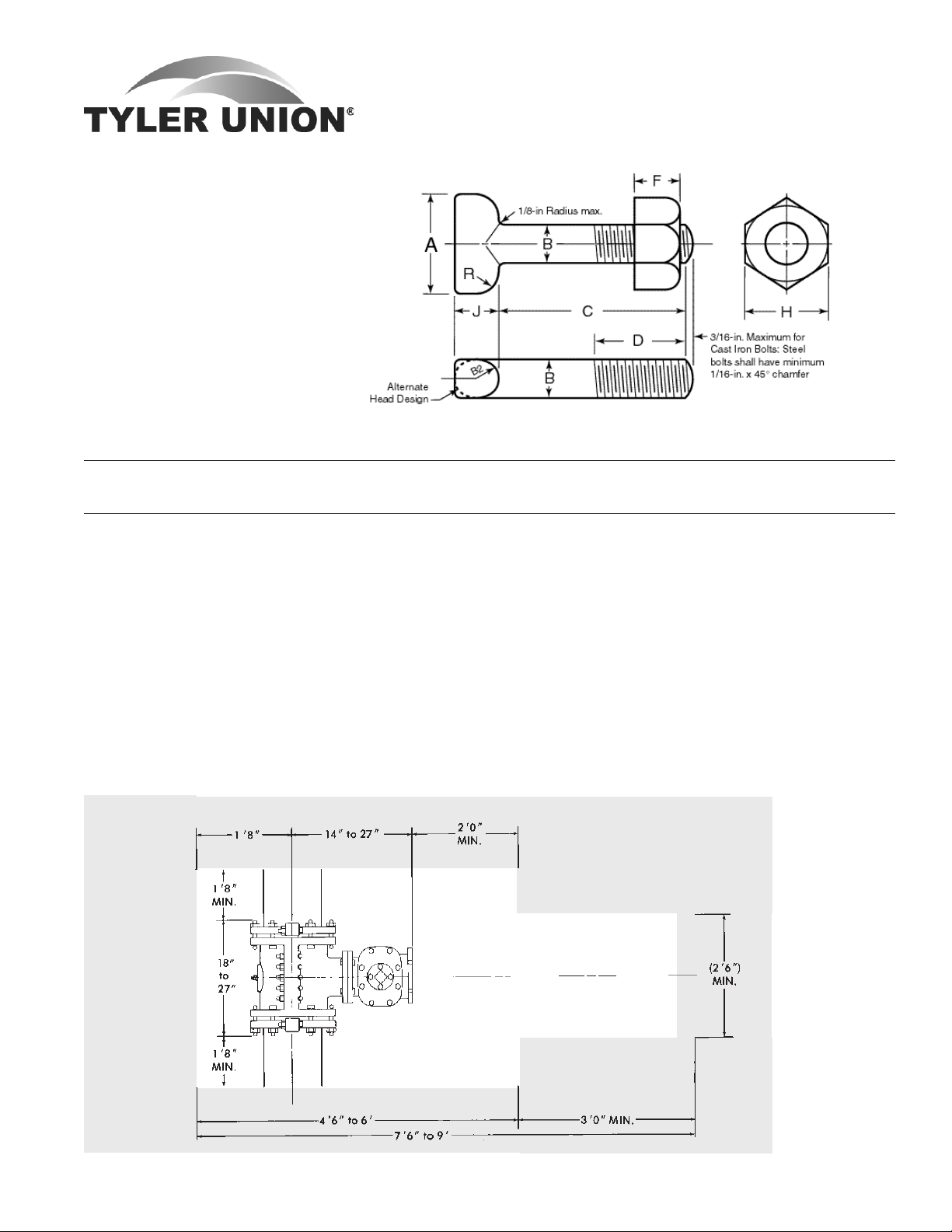
BOLTS AND NUTS FOR MECHANICAL JOINTS
ANSI/AWWA C111/A21.11
NOTES:
1. Dimension “B” is unthreaded shank.
2. Draft, when required to be
6 degree maximum, may
be deducted from bolt head
dimensions, and radius
(B/2) may be changed to
suit draft.
3. Gates, if required, may
protrude a maximum of
1/8 inch above the top of
the bolt head.
4. Chamfer is optional if
threads are rolled.
T-Head (Low alloy steel) Bolts and Nuts
Dimensions in Inches
A B C D† Threads F H J R
Size ± 0.05 +0.030 +0.25 per Inch +0.15 Max.
Inches -0.074 -0.06 E †† -0.03
Á x 3 1.50 0.625 3.0 2.00 11 0.625±.04 1.062-.04 0.625 0.312
¾x 3½ 1.75 0.750 3.5 2.50 10 0.750±.06 1.250-.06 0.750 0.375
¾x4 1.75 0.750 4.0 3.00 10 0.750±.06 1.250-.06 0.750 0.375
¾ x4½ 1.75 0.750 4.5 3.00 10 0.750±.06 1.250-.06 0.750 0.375
¾x 5 1.75 0.750 5.0 3.00 10 0.750±.06 1.250-.06 0.750 0.375
1x6 2.25 1.000 6.0 3.00 8 1.000±.08 1.625-.08 1.000 0.500
1¼x6½ 2.50 1.250 6.5 3.50 7 1.250±.08 2.000-.08 1.250 0.625
* The tolerance for cast iron bolts is ±0.03 in. If threads are rolled, the body diameter may be reduced to the
approximate pitch diameter of the thread.
† Tolerance: +3, — 0 threads.
†† Number of threads per inch - course-thread series (ANSI/ASME B1.1), Class 2A, external fit UNC2A and Class
2B, UNC2B (ANSI/ASME B1.2).
Excavation dimensions - MJ 4" through 12" Tapping Sleeves for Ductile Pipe
Tyler Utilities Division • 11910 CR 492 • Tyler, Texas 75706 • (800) 527-8478
02/01/08 Union Foundry Company • Box 309 • Anniston, Alabama 36202 • (800) 226-7601 53

MECHANICAL JOINT GASKETS
ANSI/AWWA C111/A21.11
Mechanical Joint Gasket Dimensions in Inches
Pipe Pipe A B C D E F G
Size OD ± 0.01" ±1% ± 0.01% ± 0.01" ± 0.02"
2* 2.50 .48 .62 .31 2.48 .12 .15 1.05
3 3.96 .48 .62 .31 3.86 .12 .15 1.05
4 4.80 .62 .75 .31 4.68 .16 .22 1.22
6 6.90 .62 .75 .31 6.73 .16 .22 1.22
8 9.05 .62 .75 .31 8.85 .16 .22 1.22
10 11.10 .62 .75 .31 10.87 .16 .22 1.22
12 13.20 .62 .75 .31 12.95 .16 .22 1.22
14 15.30 .62 .75 .31 14.99 .16 .22 1.22
16 17.40 .62 .75 .31 17.07 .16 .22 1.22
18 19.50 .62 .75 .31 19.13 .16 .22 1.22
20 21.60 .62 .75 .31 21.20 .16 .22 1.22
24 25.80 .62 .75 .31 25.34 .16 .22 1.22
30 32.00 .73 1.00 .38 31.47 .16 .37 1.54
36 38.30 .73 1.00 .38 37.67 .16 .37 1.54
42 44.50 .73 1.00 .38 43.78 .16 .37 1.54
48 50.80 .73 1.00 .38 49.98 .16 .37 1.54
Not included in AWWA C111. Manufacturer's Standard.
Mechanical Joint Transition Gasket Dimensions in Inches
Pipe A B C D E F G
Size ± 0.01" ±1% ± 0.01" ± 0.02"
3 .70 .62 .31 3.45 .16 .37 1.11
4 .77 .75 .31 4.43 .16 .37 1.26
6 .76 .75 .31 6.53 .16 .36 1.25
8 .82 .75 .31 8.50 .16 .42 1.27
10 .79 .75 .31 10.59 .16 .39 1.26
12 .84 .75 .31 12.56 .16 .44 1.28
Tyler Utilities Division • 11910 CR 492 • Tyler, Texas 75706 • (800) 527-8478
54 Union Foundry Company • Box 309 • Anniston, Alabama 36202 • (800) 226-7601 02/01/08

MJ FIELD LOK®
A RESTRAINT REVOLUTION. Spend less time -
and money - restraining mechancial joint fittings
with the new MJ FIELD LOK® Gasket.
UL Listed and FM approved.
•
Proven joint restraint technology.
•
No learning curve - installs just like a standard
•
mechanical joint gasket and gland.
No more need for time-consuming thrust blocks or
•
heavy lug-type restraints.
No loose wedges or torque-off control nuts to get
•
lost or broken.
Can be disassembled just like a standard mechani-
•
cal joint.
Suitable for potable water and wastewater applica-
•
tions.
The state-of-the-art MJ FIELD LOKTM Gland is
•
designed for maximum strength and easy product
identification.
MJ FIELD LOK® Gaskets are provided as part of a kit
•
that also includes the MJ FIELD LOKTM Gland, nuts
and bolts.
PROVEN JOINT
RESTRAINT TECHNOLOGY
NO LEARNING CURVE
FOR DUCTILE IRON
AND PVC PIPE
CURRENTLY AVAILABLE:
Ductile Iron — 4" - 24"
PVC — 4" - 12"
MJ FIELD LOK® Gasket Series DI
•
Can be used on any Pressure Class or Special Thickness
Class Ductile Iron pipe up to 350 psi.
•
Stainless steel locking segments provide proven joint
restraint technology.
MJ FIELD LOK® Gasket Series PV
•
Can be used on any thickness class of AWWA C900 PVC
pipe.
•
Pressure rated at a 2:1 safety factor, based on the pressure rating of the pipe on which it is installed.
•
Ductile iron locking ring provides proven joint restraint
technology.
MJ FIELD LOK® Gland
•
Highly engineered to provide the strength and
rigidity necessary for restrained joint applications.
•
Installs just like a standard mechanical joint gland.
•
All ductile iron components are manufactured to ASTM
A536 Grade 70-50-05.
MJ FIELD LOK® Gasket Series PV
MJ FIELD LOK® Gland
MJ FIELD LOK® Gasket Series DI
Tyler Utilities Division • 11910 CR 492 • Tyler, Texas 75706 • (800) 527-8478
02/01/08 Union Foundry Company • Box 309 • Anniston, Alabama 36202 • (800) 226-7601 55

Application Notes:
1. MJ FIELD LOK® Gaskets are
designed to seal and restrain a
centrifugally cast ductile iron or PVC
pipe spigot in either a ductile iron
pipe or a ductile iron fitting bell.
2. MJ FIELD LOK Gaskets are
available to fit mechanical joints
conforming to AWWA C110 or
AWWA C153 in 4" - 24" sizes.
3. If ductile iron pipe with a lower
pressure rating is used, then the
lower pressure rating will apply to
the MJ FIELD LOK Gasket also.
MJ FIELD LOK® Gasket Series DI
APPROX.
SIZE PIPE ORDER NO. OF PRESSURE KIT
(Inches) OD NUMBER SEGMENTS RATING WEIGHT
4 4.80 DI04 3 350 7.3
6 6.90 DI06 4 350 10.9
8 9.05 DI08 6 350 13.5
10 11.10 DI10 9 350 18.5
12 13.20 DI12 13 350 19.7
14 15.30 DI14 18 350 26.9
16 17.40 DI16 24 350 31.8
18 19.50 DI18 30 250 49.8
20 21.60 DI20 36 250 59.7
24 25.80 DI24 52 250 81.3
4. MJ FIELD LOK Gaskets require 90 ft-lb
of bolt torque for 4" - 8" gaskets, and
120 ft-lb of bolt torque for 10" - 12"
inch gaskets. Most common 1/2" drive
air powered impact wrenches are
capable of applying these torques.
5. MJ FIELD LOK Gaskets are
suitable for either potable water or
wastewater applications.
6. MJ FIELD LOK Gaskets are
NSF approved, UL Listed and
FM Approved.
7. MJ FIELD LOK Gasket Series DI
products are not recommended for
use with cast iron pipe, plastic pipe,
oversize pipe, metric pipe, or for use
as a “transition” gasket.
8. MJ FIELD LOK Gasket Series PV
products are not recommended for
use with cast iron pipe, ductile iron
pipe, oversize pipe, metric pipe, or
for use as a “transition” gasket.
9. MJ FIELD LOK Gaskets are warranted
only when used with MJ FIELD LOKTM
Gland.
MJ FIELD LOK® Gasket Series PV
PRESSURE PRESSURE APPROX.
SIZE PIPE ORDER RATING RATING KIT
(Inches) OD NUMBER DR-18 DR-14 WEIGHT
(psi) (psi)
4 4.80 PV04 150 200 7.8
6 6.90 PV06 150 200 11.8
8 9.05 PV08 150 200 14.8
10 11.10 PV10 150 200 20.1
12 13.20 PV12 150 200 21.6
MJ FIELD LOKTM Gland
MJ FIELD LOK® Gland (See illustration at right)
DIMENSION
SIZE WEIGHT A B C D E
(Inches) (pounds) (Outside Dim) (Bolt Hole) (Inside Dia.) (OD Lip) (Gland Height)
4 3.3 8.88 7.50 4.90 5.92 1.75
6 5.0 10.87 9.50 7.00 8.02 2.00
8 7.2 13.13 11.75 9.15 10.17 2.25
10 10.2 15.38 14.00 11.20 12.22 2.25
12 11.0 17.63 16.25 13.30 14.32 2.25
14 17.2 20.13 18.75 15.44 16.40 2.51
16 25.0 22.38 21.00 17.54 18.50 2.75
18 38.0 24.75 23.25 19.64 20.60 3.14
20 46.0 27.00 25.50 21.74 22.70 3.20
24 64.0 31.50 30.00 25.94 26.90 3.57
Suggested Specifications:
Joint restraint for mechanical joint pipe and fittings shall be the MJ FIELD LOK® Gasket. The restraint system shall be completely integral to the
gasket, requiring only standard mechanical joint assembly techniques. The restraining system for ductile iron shall be pressure rated to 350
psi in sizes up to and including 16" ; 18", 20" and 24" are rated for 250 psi. The restraining system for PVC shall be rated at a 2:1 safety factor
for the pipe on which it is installed. The restraining system shall be rated in accordance with the performance requirements of ANSI/AWWA
C111/A21.11 Rubber Gasket Joints for Ductile-Iron Pressure Pipe and Fittings.
Tyler Utilities Division • 11910 CR 492 • Tyler, Texas 75706 • (800) 527-8478
56 Union Foundry Company • Box 309 • Anniston, Alabama 36202 • (800) 226-7601 02/01/08

20U - Epoxy Coating
of Watermain Fittings
Revised 10/09
SUBMITTAL
(Current Revisions for All Standards Apply)
Epoxy Coating
Watermain Fittings 2”-48” shall be coated with 6-8 mil nominal thickness fusion
bonded epoxy in accordance with and shall meet all applicable terms and
provisions of ANSI/AWWA C116/A21.16-09.
Epoxy coating material used by Tyler/Union are tested to the requirements of and
are in compliance with NSF 61.
Tyler Pipe Company • 11910 CR 492 • Tyler, Texas 75706 • (800) 527-8478
Union Foundry Company • 1501 W. 17th Street • Anniston, Alabama 36202 • (800) 226-7601
www.tylerunion.com

21U - Cement Lining
Asphaltic Coating
of Watermain Fittings
Revised 10/09
SUBMITTAL
(Current Revisions for All Standards Apply)
Cement Lining and Coating
The Cement Lining and Asphaltic Coating of Watermain Fittings furnished by
Tyler/Union is applied and seal coated with a bituminous material as specified by
and in accordance with the terms and provisions of standard ANSI/AWWA C104/
A21.4-08.
All coating materials used by Tyler/Union are tested to the requirements of and
are in compliance with NSF 61.
Tyler Pipe Company • 11910 CR 492 • Tyler, Texas 75706 • (800) 527-8478
Union Foundry Company • 1501 W. 17th Street • Anniston, Alabama 36202 • (800) 226-7601
www.tylerunion.com

22U - Mechanical Joint
C110/A21.10
Full Body
Revised 10/09
SUBMITTAL
(Current Revisions for All Standards Apply)
SIZES: ............................ 2” through 48”
STANDARDS: ................. ANSI/AWWA C110/A21.10-08 and 3”-12” UL Listed (EX2111)
Note: Cast with tested and traceable ASTM A536 Ductile Iron
PRESSURE RATING: 2”- 24” rated @ 350 PSI; 30”- 48” & all fittings with flanged branches rated @ 250 psi
Note: With use of special flange gasket 2”-24” flanged fittings can be rated @ 350 psi
DEFLECTION: ................. Upon completion of installation, mechanical joint fittings 2" - 12" are rated for a
maximum of 5° deflection and 14" - 48", a maximum of 3° deflection.
NSF-61: ......................... Meets all requirements, UL Registered
BITUMINOUS
COATING: ...................... ANSI/AWWA C104/A21.4-08
CEMENT LINING: .......... ANSI/AWWA C104.A21.4-08,
Double cement lining available
EPOXY COATING:.......... ANSI/AWWA C116/A21.16-09
Note: Epoxy coated fittings are
available to the specification(s)
required for your application(s)
BARE: ............................. Available
BOLTS: ........................... ANSI/AWWA C111/A21.11-7
INSTALLATION: ............. AWWA C600-99 using pipe
conforming to ANSI/AWWA C151/A21.51-02
JOINT DIMENSIONS IN INCHES
Size A B C D F Ø X J K
2 2.50 2.50 3.39 3.50 2.61 28° ¾ 4.75 6.25 6.25 .75 .62 ----- .31 .63 .44
3 3.96 2.50 4.84 4.94 4.06 28° ¾ 6.19 7.69 7.69 .94 .62 1.37 .31 .63 .52
4 4.80 2.50 5.92 6.02 4.90 28° Â 7.50 9.12 9.12 1.00 .75 1.50 .31 .75 .65
6 6.90 2.50 8.02 8.12 7.00 28° Â 9.50 11.12 11.12 1.06 .88 1.63 .31 .75 .70
8 9.05 2.50 10.17 10.27 9.15 28° Â 11.75 13.37 13.37 1.12 1.00 1.75 .31 .75 .75
10 11.10 2.50 12.22 12.34 11.20 28° Â 14.00 15.69 15.62 1.19 1.00 1.75 .31 .75 .80
12 13.20 2.50 14.32 14.44 13.30 28° Â 16.25 17.94 17.88 1.25 1.00 1.75 .31 .75 .85
14 15.30 3.50 16.40 16.54 15.44 28° Â 18.75 20.31 20.25 1.31 1.25 2.00 .31 .75 .89
16 17.40 3.50 18.50 18.64 17.54 28° Â 21.00 22.56 22.50 1.38 1.31 2.06 .31 .75 .97
18 19.50 3.50 20.60 20.74 19.64 28° Â 23.25 24.83 24.75 1.44 1.38 2.13 .31 .75 1.05
20 21.60 3.50 22.70 22.84 21.74 28° Â 25.50 27.08 27.00 1.50 1.44 2.19 .31 .75 1.12
24 25.80 3.50 26.90 27.04 25.94 28° Â 30.00 31.58 31.50 1.62 1.56 2.31 .31 .75 1.22
30 32.00 4.00 33.29 33.46 32.17 20° 1¿ 36.88 39.12 39.12 1.81 2.00 2.75 .38 1.00 1.50
36 38.30 4.00 39.59 39.76 38.47 20° 1¿ 43.75 46.00 46.80 2.00 2.00 2.75 .38 1.00 1.80
42 44.50 4.00 45.79 45.96 44.67 20° 1À 50.62 53.12 53.12 2.00 2.00 2.75 .38 1.00 1.95
48 50.80 4.00 52.09 52.26 50.97 20° 1À 57.50 60.00 60.00 2.00 2.00 2.75 .38 1.00 2.20
Tyler Pipe Company • 11910 CR 492 • Tyler, Texas 75706 • (800) 527-8478
Union Foundry Company • 1501 W. 17th Street • Anniston, Alabama 36202 • (800) 226-7601
www.tylerunion.com
1
K2 L M N O P S

23U - Mechanical Joint
C153/A21.53
Compact
Revised 10/09
SUBMITTAL
(Current Revisions for All Standards Apply)
SIZES: ............................ 2” through 48” (2” Not Referenced in C153/A21.53)
STANDARDS: ................. ANSI/AWWA C153/A21.53-06 and NFPA 3”-12” UL Listed (EX2111)
Note: Cast with tested and traceable ASTM A536 Ductile Iron
PRESSURE RATING: 2”- 24” rated @ 350 PSI; 30”- 48” & all fittings with Flanged branches rated @ 250 PSI
Note: With use of special flange gasket 2”-24” flanged fittings can be rated @ 350 psi
Note: Compact Wyes over 12” are not pressure rated. Contact manufacturer for rating
in your application.
DEFLECTION: ................. Upon completion of installation, Mechanical Joint fittings 2”-12” are rated for a maxi-
mum of 5° deflection and 14”–48” a maximum of 3° deflection
NSF-61: ......................... Meets all requirements, UL Registered (2”-48”)
BITUMINOUS
COATING: ...................... ANSI/AWWA C104/A21.4-08
CEMENT LINING: .......... ANSI/AWWA C104.A21.4-08,
Double cement lining available
EPOXY COATING:.......... ANSI/AWWA C116/A21.16-09
Note: Epoxy coated fittings are
available to the specification
required for your application(s)
BARE: ............................. Available
BOLTS: ........................... ANSI/AWWA C111/A21.11-7
INSTALLATION: ............. Per AWWA C600-99 using pipe
conforming to ANSI/AWWA
C151/A21.51-02
JOINT DIMENSIONS IN INCHES BOLTS
Size A Dia. B C Dia. D Dia. F Dia. J Dia. K
3 3.96 2.50 4.84 4.94 4.06 6.19 7.62 7.69 .58 .62 .39 .33 ¾ Á x3 4
4 4.80 2.50 5.92 6.02 4.90 7.50 9.06 9.12 .60 .75 .39 .34 Â ¾x3½ 4
6 6.90 2.50 8.02 8.12 7.00 9.50 11.06 11.12 .63 .88 .43 .36 Â ¾x3½ 6
8 9.05 2.50 10.17 10.27 9.15 11.75 13.31 13.37 .66 1.00 .45 .38 Â ¾x4 6
10 11.10 2.50 12.22 12.34 11.20 14.00 15.62 15.62 .70 1.00 .47 .40 Â ¾x4 8
12 13.20 2.50 14.32 14.44 13.30 16.25 17.88 17.88 .73 1.00 .49 .42 Â ¾x4 8
14 15.30 3.50 16.40 16.54 15.44 18.75 20.31 20.25 .79 1.25 .55 .47 Â ¾x4½ 10
16 17.40 3.50 18.50 18.64 17.54 21.00 22.56 22.50 .85 1.31 .58 .50 Â ¾x4½ 12
18 19.50 3.50 20.60 20.74 19.64 23.25 24.83 24.75 1.00 1.38 .68 .54 Â ¾x4½ 12
20 21.60 3.50 22.70 22.84 21.74 25.50 27.08 27.00 1.02 1.44 .69 .57 Â ¾x4½ 14
24 25.80 3.50 26.90 27.04 25.94 30.00 31.58 31.50 1.02 1.56 .75 .61 Â ¾x5 16
30 32.00 4.00 33.29 33.46 32.17 36.88 39.12 39.12 1.31 2.00 .82 .66 1¿ 1x6 20
36 38.30 4.00 39.59 39.76 38.47 43.75 46.00 46.00 1.45 2.00 1.00 .74 1¿ 1x6 24
42 44.50 4.00 45.79 45.96 44.67 50.62 53.12 53.12 1.45 2.00 1.25 .82 1À 1¼x6½ 28
48 50.80 4.00 52.09 52.26 50.97 57.50 60.00 60.00 1.45 2.00 1.35 .90 1À 1¼x6½ 32
Tyler Pipe Company • 11910 CR 492 • Tyler, Texas 75706 • (800) 527-8478
Union Foundry Company • 1501 W. 17th Street • Anniston, Alabama 36202 • (800) 226-7601
www.tylerunion.com
1
Dia. K2 Dia. L M S T X Size No.

24U-Mechanical Joint
Retainer Gland
C153/A21.53
Revised 10/09
SUBMITTAL
(Current Revisions for All Standards Apply)
SIZES: ............................ 3” through 24”
STANDARDS: ................. ANSI/AWWA C153/A21.53-06 cast with tested and traceable ASTM A586 Ductile Iron.
Sizes 3”-12” are recommended for Class 56 ductile pipe
Sizes 14”-24” are recommended for Class 53 through Class 56 ductile pipe
DEFLECTION: ................. Maximum recommended deflection of joints is 2° for 3” through 12” and 1° for 14”
through 24”
BOLTS: ........................... ANSI/AWWA C111/A21.11-7, ANSI/AWWA C153/A21.53-06, standard T-Bolts. The set
screws are square headed with Type C knurled cup points, 4140 grade alloy steel that is
heat treated to a Rockwell “C” 45/53 case hardness and are shipped assembled in the
gland
PRESSURE RATING: ....... 3”-24” rated @ 350 psi
NSF-61: ......................... Meets all requirements, UL Registered
PRIMER COATING: ........ ANSI/AWWA C104/A21.4-08
INSTALLATION: ............. Per Tyler Union instructions below. Note: Not for use on plain end fittings
T-BOLTS (to secure gland to hub)
4”-24” Retainer gland T-Bolts torque to 60 ft lbs
SET SCREWS (to secure gland to pipe)
Set screw recommended torque value is 75 ft lbs
Wash bell and plain end with soapy water, 1.
then slip gland and gasket over plain end
with the small side of the gasket and ring
side of of the gland facing the bell.
2. Slip plain end into bell. Brush soapy water
on gasket. This lubricates the gasket and
allows it to slip easily into place. Push
gasket into bell making sure it is evenly in
the bell gasket landing.
3. Slide the gland into position against the
back of the gasket. Align bolt holes, insert
T-bolts and tighten nuts to finger tight.
4. Snug up all T-bolt nuts evenly. Alternating
at 180°, tighten the T-bolt nuts to a torque
of: 3” - 60 foot pounds
4” thru 24” - 90 foot pounds.
5. Snug up all set screws evenly. Using a
torque wrench, tighten the set screws
alternating at 180° to the recommended
torque value of 75 foot pounds. If required
double check set screws immediately.
Pressure Gland Pipe O.D. D.I. Pipe No of Size of
Rating, O.D. O.D. Wall Set Set Gland Wt w/
Size psi B A Class Screws Screws Wt Acces.
3 350 7.69 3.96 50-56 4 Á x2 4 8
4 350 9.12 4.80 50-56 4 Á x2 5 11
6 350 11.12 6.90 50-56 6 Á x2 9 16
8 250 13.37 9.05 50-56 9 Á x2 13 21
10 250 15.62 11.10 50-56 12 Á x2 17 26
12 150 17.88 13.20 50-56 16 Á x2 20 28
14 250 20.25 15.30 53-56 20 Á x2½ 44 55
16 200 22.50 17.40 53-56 24 Á x2½ 54 64
18 200 24.75 19.50 53-56 24 Á x2½ 62 72
20 200 27.00 21.60 53-56 28 Á x3 76 91
24 150 31.50 25.80 53-56 32 Á x3 103 118
* Not included in AWWA C110
Tyler Pipe Company • 11910 CR 492 • Tyler, Texas 75706 • (800) 527-8478
Union Foundry Company • 1501 W. 17th Street • Anniston, Alabama 36202 • (800) 226-7601
www.tylerunion.com

25U-Compact
Mechanical Joint
Tapping Sleeve For
Ductile or Cast Iron Pipe
Revised 10/09
SUBMITTAL
(Current Revisions for All Standards Apply)
SIZES: ...................... For 6” to 12” Cast Iron or Ductile pipe with 4” to 12” side flanged outlet
with ¾” tap at branch.
STANDARDS: ........... Mechanical and *Flanged joints comply with ANSI/AWWA C153/A21.53-
06 cast with tested and traceable ASTM A586 Ductile Iron. Ductile Iron
Mechanical Joint Tapping Sleeves are produced in accordance with Tyler
Union manufacturer’s standard. Outside diameter specification ranges are
per the standards provided herein.
Note: Recess dimensions are per Manufacturer’s Standardization Society
standard practice SP-60.
PRESSURE RATING: . 6”- 12” Assemblies rated @ 250 PSI.
GASKETS: ................ SBR Mechanical Joint and Split gaskets are per ANSI/AWWA C111/
A21.11-7, armor tipped with coiled brass wire spring.
NSF-61: ................... Meets all requirements
BITUMINOUS
COATING: ................ ANSI/AWWA C104/A21.4-08
CEMENT LINING: .... Tapping Sleeves are unlined to ensure
they fit over the pipe being tapped.
FLANGE: .................. ANSI Class 125B
FLANGE THICKNESS
: ANSI/AWWA C153/A21.53-06
BOLTS: ..................... ANSI/AWWA C111/A21.11-7
DEFLECTION: ........... Deflection is not recommended
INSTALLATION: ....... Per Tyler Union instructions below
Clean pipe, insert side gasket into back 1.
half of gasket grooves. Make sure ends are
ush with or slightly protrude into the end
gasket seating area.
Bolt sleeve halves together and trim side 2.
gaskets as necessary. MAKE SURE
SLEEVE WILL ROTATE FREELY ON PIPE.
Install end gaskets, locating cut ends 90° 3.
from side gasket If pipe is maximum OD,
stretch gasket to make certain cut ends
match with no gap in between.
Install glands and bolts-rotate sleeve to 4.
desired position. Be sure pipe is centered
inside the sleeve.
Tighten gland bolts alternately, using 80 to 5.
90 foot pounds.
After assembly, PRESSURE TEST ALL 6.
JOINTS BEFORE TAPPING. If additional
tightening is required, release pressure and
relax tension on gland bolts before tighten-
ing side bolts.
O.D. Range
Dimensions DI Weight
Size A B C D E F Min. Max. DI
6x4 5.016 .250 7.50 15.75 8.00 12.75 6.85 7.15 104
6 7.016 .312 9.50 15.75 8.00 12.75 6.85 7.15 108
8x4 5.016 .250 7.50 16.50 9.00 13.375 9.00 9.35 134
8x6 7.016 .312 9.50 16.50 9.00 13.375 9.00 9.35 140
8 9.016 .312 11.75 16.50 9.00 13.375 9.00 9.35 148
10x4 5.016 .250 7.50 24.00 11.00 20.75 11.04 11.45 236
10x6 7.016 .312 9.50 24.00 11.00 20.75 11.04 11.45 240
10x8 9.016 .312 11.75 24.00 11.00 20.75 11.04 11.45 246
10 11.016 .312 14.25 24.00 11.00 20.75 11.04 11.45 257
12x4 5.016 .250 7.50 26.50 12.00 23.25 13.14 13.56 273
12x6 7.016 .312 9.50 26.50 12.00 23.25 13.14 13.56 286
12x8 9.016 .312 11.75 26.50 12.00 23.25 13.14 13.56 292
12x10 11.016 .312 14.25 26.50 12.00 23.25 13.14 13.56 303
12 13.016 .312 17.00 26.50 12.00 23.25 13.14 13.56 320
Tyler Pipe Company • 11910 CR 492 • Tyler, Texas 75706 • (800) 527-8478
Union Foundry Company • 1501 W. 17th Street • Anniston, Alabama 36202 • (800) 226-7601
www.tylerunion.com

26U - Union Tite
Tyton Joint - Push On
Compact Fittings
Revised 10/09
SUBMITTAL
(Current Revisions for All Standards Apply)
SIZES: ...................... 4” through 24”
STANDARDS: ........... ANSI/AWWA C153/A21.53-06 and 3”-12” UL Listed (EX2111)
Note: Cast with tested and traceable ASTM A536 Ductile Iron
PRESSURE RATING: 350 PSI; Except for wyes and flanged branch fittings
Note: Flanged branch Non-Wye fittings can be rated @ 350 PSI with the
use of special gasket
NSF-61: ................... Meets all requirements, UL Certified
BITUMINOUS
COATING: ................ ANSI/AWWA C104/A21.4-08
CEMENT LINING: .... ANSI/AWWA C104.A21.4-08
EPOXY COATING:.... ANSI/AWWA C116/A21.16-09
Note: Epoxy coated fittings are
available to the specification(s) required for your application(s)
BELL SOCKETS: ........ ANSI/AWWA C116/A21.16-09
BOLTS: ..................... ANSI/AWWA C151/A21.51-09 and AWWA C900-97, Table 2
BARE: ....................... Available
DEFLECTION: ........... 5 Degrees Maximum
RESTRAINING LUGS:Provided on 12” and smaller fittings and the lug pattern for all sizes
accommodates most gripper-type restraints.
Note: Restraining lugs available for 14”-24” fittings provided sufficient
time is available to make pattern adaptations.
INSTALLATION: ....... Per AWWA C600-99 using pipe conforming to ANSI/AWWA
C151/A21.51-02
BELL DIMENSIONS IN INCHES FOR UNION-TITE FITTINGS
Pipe
Size A B B.C. C D E
4 5.04 6.38 7.88 4.16 2.25 .35
6 7.14 8.52 10.50 4.29 2.25 .37
8 9.32 10.90 12.88 4.78 2.25 .39
10 11.37 12.91 14.69 4.98 2.25 .41
12 13.47 15.12 17.19 4.98 2.25 .43
14 15.64 18.12 ... 5.40 2.25 .51
16 17.74 20.32 ... 5.40 2.25 .52
18 19.83 22.52 ... 5.40 2.25 .59
20 21.94 24.29 ... 5.40 2.25 .60
24 26.14 29.14 ... 5.65 2.50 .62
Tyler Pipe Company • 11910 CR 492 • Tyler, Texas 75706 • (800) 527-8478
Union Foundry Company • 1501 W. 17th Street • Anniston, Alabama 36202 • (800) 226-7601
www.tylerunion.com

28U - Flanged Joint
C110/A21.10
Full Body
Revised 10/09
SUBMITTAL
(Current Revisions for All Standards Apply)
SIZES: ............................ 2” through 48”
STANDARDS: ................. ANSI/AWWA C110/A21.10-08
Note: Cast with tested and traceable ASTM A536 Ductile Iron
PRESSURE RATING: ....... 2”-48” rated @ 250 PSI
Note: With the use of special flange gasket 2”-24” flanged fittings can be rated
@ 350 psi
DEFLECTION: ................. Deflection is not recommended for flanged joint fittings due to the rigidity of the joint
upon completion of installation.
NSF-61: ......................... Meets all requirements, UL Certified
COATING: ...................... ANSI/AWWA C104.A21.4-08 Bituminous and Tnemec 140N-1211
CEMENT LINING: .......... ANSI/AWWA C104.A21.4-08
EPOXY COATING:.......... ANSI/AWWA C116/A21.16-09
Note: Epoxy coated fittings are available to the specification(s) required for your
application(s)
FLANGES: ...................... ANSI Class 125 B16.1
Note: *ANSI Class 250 B16.1 flanged fittings available
Note: *Due to larger bolt sizing and bolt circle class 250 flanges are not compatible
with class 125 flanged fittings.
FLANGE THICKNESS: .... ANSI/AWWA C151/A21.51-05; Standard Class 125 template for drilling bolt holes
Note: Drilling templates are in multiplies of 4, so that fittings may be made to face in
any quarter. Bolt holes shall straddle the center line.
BOLTS: ........................... ANSI/AWWA C111/A21.11-7
INSTALLATION: ............. Per AWWA C600-99 using pipe conforming to ANSI/AWWA C151/A21.51-02
FLANGE DETAILS
Nominal Dia. of Flange
Pipe Size Flange Bolt Thickness Bolt Hole Number Bolt Dia.
Inch O.D. Circle T Diameter of Holes & Lengths
2 6 4.75 .62 .75 4 Á x2¼
3 7.5 6 .75 .75 4 Á x2½
4 9 7.5 .94 .75 8 Á x3
6 11 9.5 1.00 .875 8 ¾x3½
8 13.5 11.75 1.12 .875 8 ¾x3½
10 16 14.25 1.19 1.00 12 Â x4
12 19 17 1.25 1.00 12 Â x4
14 21 18.75 1.38 1.125 12 1x4½
16 23.5 21.25 1.44 1.125 16 1x4½
18 25 22.75 1.56 1.25 16 ¿ x5
20 27.5 25 1.69 1.25 20 ¿ x5
24 32 29.5 1.88 1.375 20 ¼x5½
30 38.75 36 2.12 1.375 28 1¼x6½
36 46 42.75 2.38 1.675 32 1½x7
42 53 49.50 2.62 1.625 36 1½x7½
48 59.50 56.00 2.75 1.625 44 1½x8
Tyler Pipe Company • 11910 CR 492 • Tyler, Texas 75706 • (800) 527-8478
Union Foundry Company • 1501 W. 17th Street • Anniston, Alabama 36202 • (800) 226-7601
www.tylerunion.com

29U-Cast Iron
Service, Valve Boxes
& Components
Revised 10/09
SUBMITTAL
(Current Revisions for All Standards Apply)
SIZES: ............................ Adjustable Slip and Screw type with standard assembled lengths ranging from 15” to
72”, not including risers and extensions.
Note: See catalog or website for complete listing of components
STANDARDS: ................. Produced in accordance with and meet all applicable terms and provisions of ASTM
A-48. Cast with 30B or 35B class cast iron. When properly installed will meet American
Association of State Highway Officials (AASHO) H2O wheel load rating.
INSTALLATION: ............. Per AWWA M44, Manual of Water Supply Practices
6500 SCREW TYPE
Extension
Componets In Inches
12T & 12B 15-21
12T & 15B 18-24
15T & 15B 21-27
15T & 21B 24-33
15T & 27B 30-39
18T & 27B 30-42
18T & 33B 36-48
24T & 33B 36-54
24T & 39B 42-60
30T & 39B 41-64
6850 SCREW TYPE
Extension
Components Height
10T + 15B 19-22
10T + 24B 27-32
16T + 24B 27-37
16T + 30B 33-43
16T + 36B 39-50
26T + 30B 36-52
26T + 36B 39-60
26T + 24B + #60 Ext 51-71
26T + 36B + #60 Ext 62-82
6855 SLIP TYPE
Extension
Components Height
10T + 15B 19-22
10T + 24B 27-32
16T + 24B 27-37
16T + 30B 33-43
16T + 36B 39-50
26T + 30B 36-52
26T + 36B 39-60
26T + 24B + #60 Ext 51-71
26T + 36B + #60 Ext 62-82
7126 SLIP TYPE
Extension
Components Height
26T + 30B 45-66
26T + 36B 51-72
26T + 24B 63-84
26T + 15B 74-94
6860 SCREW TYPE
Extension
Components) Height
10T + 12B 27-37
16T + 18B 33-42
16T + 24B 39-49
16T + 30B 45-54
16T + 36B 51-60
26T + 30B 45-66
26T + 36B 51-72
Tyler Pipe Company • 11910 CR 492 • Tyler, Texas 75706 • (800) 527-8478
Union Foundry Company • 1501 W. 17th Street • Anniston, Alabama 36202 • (800) 226-7601
www.tylerunion.com

Other TYLER Products Include
Ductile Iron C153 Fittings in MJ and Union-Tite
Ductile Iron C110 Fittings in MJ and Flanged
Ductile Iron Compact Flanged Fittings
Swivel MJ Fittings For Hydrants
Cast Iron Service & Valve Boxes
www.tylerunion.com
SEARCH INVENTORY for all fittings, accessories,
valve boxes, companion flanges and other products
in stock, 24 hours a day, 7 days a week.
SEE ENTIRE TYLER/UFCO CATALOG
View, print and download drawings and specifications.
FIND THE COMPLETE LIST PRICE SHEET
page-by-page. Use the index to go to the product
group
Distributed By
 Loading...