

Tyler TTV701-7 Service Manual

Service m an u al
二、Blank screen t roubl e shooti ng st eps:
NO NO
YES
YES
No
YES
Check the cathode of DI1(IN5819) if there have 10V voltage
Check
UI1(G5121)from the 6
pin have 5V voltage
Check th e circuit from
U15(MSD3393) of the 133th
pin to UI1(G5121) of the 6th pin
Check the UI1(G5121) peripheral circuit
And replace UI1
Check Q12 base
electrodeIf it is a
Check the circuit from Q12base electrode
to U15(MSD3393) of the 109 pin and
replace U15
Check the circuit from Q12
emitter electrode to back light, and
replace back light
三、Has image, no sound/low sound/distortion
YES
No
No
YES
Maximum volume,on USB/SD reading status, Use the
multimeter to test the pin 3/8 of U13 (SL6699),whether
the speaker has noise.
Whether the speaker open circuit?
Replace speaker
Check the component from the 3/8 pin o f U13
to the pin 47/46 of U15,or repl ace U15
(MSD3393)
Test U13 peripheral
components or replace U13
五、AV input no image no sound
NO
YES
NO
YES
NO
YES
Check if AV input socket is normal?
Check if AV cable is normal?
Replace AV input socket
Replace AV cable
If no sound, check ,Check AV input socket circuit from audio frequency to the external
components of
U15 34/35/36/36 pin;N o image, check if video frequency to the external
components of U15 28, 29 pin is normal
Replace the related components
Replace U15
六、Snow screen/image not clear
YES
NO
NO
YES
NO
YES
Check if power supply -10V/+15V/+10V/+3.3V/5V on PCB sockets
are normal
Whether the cable of LCD screen loose?
Tighten the cable.
Check if the circuit from PCB socket to U15 (MSD3393) is normal
Check the abnormal power supply circuit.
Check the abnormal circuit.
LCD screen abnormal.
1 2 3
5 6 74
四、DTV no signal trouble shooting steps:
NO
NO
YES
NO
YES
NO
YES
NO
YES
Whether U6(R840) 11,18,24 circuit
+3.3V voltage normal.
Select the local color system and sound system, then
start auto channel scanning
Whether the circuit from
U15 104 pin to U6(R840) 11,18,24 pin
normal?
Check if the circuit component from U15 58,59 pinto
U6(R840) 6、7 pin is normal.
Replace related component
Check if the component of U15 49/50 pin and U6(R840) 17、16 pin is normal
Replace the related components
Replace U15 or U6
When channel scanning, check if the 48 pin voltage of U15 changed on 0-3.3V range.
Check th e power supply of U 15
51/52 pin and replace U15
一、No sound, no image, blank screen troubl e shooting steps:
NO Red ligh t on
NO
YES
YES
NO
NO
YES
NO
NO YES YES
Whether the power light is on?
Whet her the
I C2(ETA1483) +5Vpower out put
normal?
Check the electrical level of U11
(SC61A05)from 1st pin is low
Check whether the 12V input voltage
of IC2 (ETA1483)’s 2nd pin is normal
Check the
related
abnormal
circuit.
Check U9 software and Y2
crystal vibration circuit,o r
U15(MSD3393)
malfunctions.
Test the power s upply of
U15(MSD3393) 3.3V/1.8V/1.2 is
normal
Whether the green light on
when press POWER
button.
Check DC input jack and
AC adapter 12V
Test battery positive
electrode : if have 4.2V
circuit is normal ,o therwise
replace U11
Check the circuit of U11 from 1 pin to the LED light.
And replace indicator lamp.
See 2nd
phenomenon: blank
screen
maintenance steps
Repair or replace the circuit of
IC2
(ETA1483)
七、USB not reading
NO
YES
NO
YES
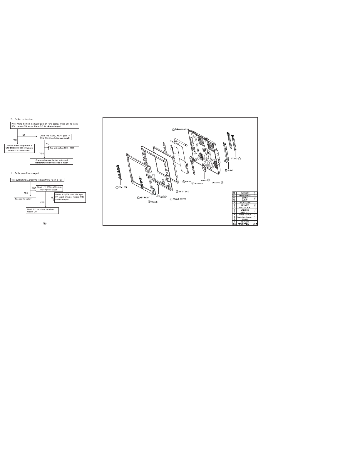
八、SD card not reading
NO
YES
NO
YES
NO
YES
Replace the socket.
Whether the socket normal?
Test USB ① pin 5V power, check the circuit
from USB ? ? to U15(MSD3393)’s 123,124 pin
Check the power supply of
USB socket and other
component.
Replace U15 (MSD3393)
Replace the socket.
Check if the socket is ok?
Test SD socket each pin to the related route
of U14(MA8121K)is Ok.
Maintenance related corresponding circuit
Test U14(MA8121K)18 pin if there have 5V power supply
Repair the related circuit
components from U15 110 pin to
U14 18 pin.
Repair the components from U14 23,24 pin to
U15 125,126 pin ,or replace U14、U15
2
3
 Loading...