

1205
ENGLISH
USER AND INSTALLATION
GUIDE H2
O
K
29005140-ENG

Keep this user guide!
In the event of any problems, please contact the retailer where
you purchased the equipment.
© This publication may not be reproduced, in part or in whole,
without the written permission of Tylö. Tylö reserves the right to
make changes in materials, construction and design.
TABLE OF CONTENTS
User Guide ......................................................................1
The control panel in general .................................................. 1
When starting for the first time ............................................. 2
Start/stop ................................................................................2
Setting temperature ................................................................2
Setting humidity level .............................................................2
Setting start time and calendar programming. ....................... 3
The SETTINGS menu ............................................................3
Locking the panel ...................................................................4
Drying mode ...........................................................................5
External ON/OFF switch (option) ........................................... 5
Extra control panel (option) ....................................................5
Installation Guide ........................................................... 6
Control panel ........................................................................ 6
External ON/OFF switch (option) ........................................... 7
Extra control panel (option) ....................................................7
Troubleshooting the control panel ............................... 8
1
USER GUIDE
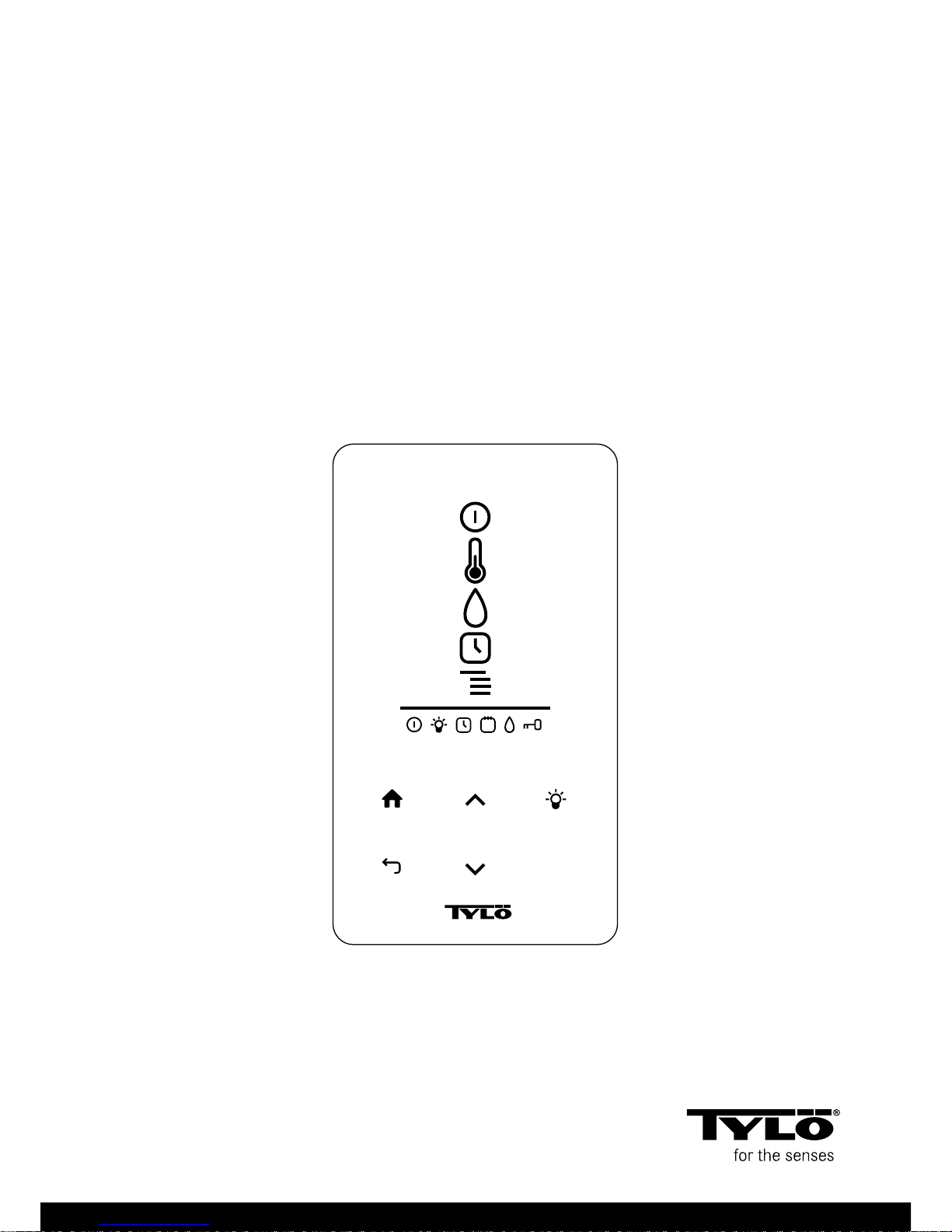
The control panel in general
The control panel is automatically activated when you pass your
hand over it.
Use UP (see Figure 1, Page 1 pos 6) and DOWN(pos 9) to
scroll through the menus.
Use UP and DOWN to increase/decrease a value when entering
data.
Confirm menu choices using OK (pos 8).
1
2
3
4
5
6
7
8
9
10
11
12
13 14 15 16 17 18
O
K
19
20
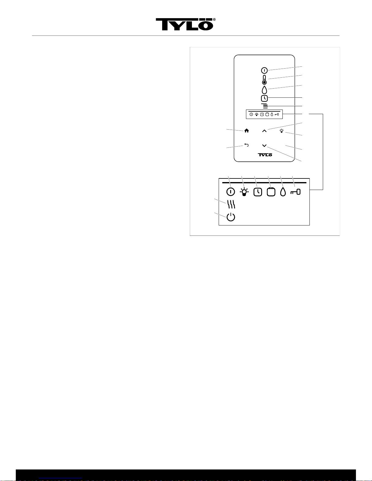
Figure 1: Main menu
1.
ON/OFF
2.
TEMPERATURE
3.
HUMIDITY: Set humidity
4.
TIMER: Program start time
5.
SETTINGS
6.
STATUS BAR: Shows the status of certain functions
(13-20)
7.
UP: One step up in the menu or increase value when enter-
ing data
8.
LIGHT
9.
OK: Confirm choice
10.
DOWN: One step down in the menu or decrease value
when entering data
11.
BACK: Go one step back in the menu or when entering
data
12.
HOME: Return to main menu
13.
ON/OFF STATUS: Shows that the sauna/steam bath is on
14.
LIGHT STATUS: Shows that the light is on
15.
TIMER STATUS: Shows that the control panel is pro-
grammed for delayed start
16.
CALENDAR STATUS: Shows that the system is calen-
dar-programmed
17.
HUMIDITY STATUS: Shows approximate reservoir level
Full symbol = full reservoir, half-full symbol = half reservoir
and flashing empty symbol = empty reservoir. Only applies
to heaters with manual water filling.
18.
LOCKED STATUS: Shows that the panel is locked
19.
DRYING STATUS: Shows that the system is in Dryingset-
ting, replaces ON/OFF STATUS
20.
STANDBY STATUS: Shows that the system is in Stand-
bysetting, replaces ON/OFF STATUS

2
When starting for the first time
Using the control panel for the first time:
1. Check the heater manual for getting started and safety precautions.
2. Pass your hand over the screen to light it up.
3. Select region (Europe, USA, Other). Use UP and DOWN to
scroll through the menu. Confirm using OK (see Figure 2,
Page 2).
Figure 2: UP, DOWN and OK
4. Select language. Confirm with OK.
5. Enter current time. Confirm with OK.
6. Enter current date (yyyy-mm-dd). Confirm with OK.
7. Select System type (Timer-controlled, Monitored or
Private).
Key to system type:
System type Timer-controlled is used for systems in which
calendar programming or delayed start are required. Maximum running time for this choice is 12 hours. After 12 hours, the
system must be shut down for at least 6 hours. A door contact
must also be connected to the sauna door to detect whether
the door is opened after the last shut-down.
System type Monitored is used for systems where there are
always personnel to monitor the sauna. No calendar programming or delayed start can be used with this choice.
System type Private is used for private systems. Max. sauna
time is 6 hours. Delayed start can be used with this choice,
but not calendar programming.
NOTE! A door contact can be used for all system
types. The contact will detect if the sauna door is
opened after the last sauna has been taken. NB:
timer-controlled systems will require a check of the
sauna and confirmation on the control panel.
8. Enter Bathtime limit (maximum time depends on system
type).
9. Enter Door contact (Yes, No).
10. Enter Auto fill and empty (automatic water filling and empty-
ing - applies to the Expression heater).
Start/stop
To start the heater:
1. Pass your hand over the screen to light it up. ON/OFF is
marked (light intensity increases) (see Figure 3, Page 2).
Figure 3: ON/OFF and ON/OFF STATUS
2. If ON/OFF is not marked, use UP to scroll to the correct posi-
tion.
3. Press OK. ON/OFF STATUS will light up in the STATUS BAR
(see Figure 1, Page 1) to show that the sauna heater is
on.
When the heater is on, the temperature and time will be shown if
no other settings are changed.
To switch off, select ON/OFF and press OK.
NOTE! When the heater is switched off or the set operating time expires, it will switch into drying mode. The
heating element will run for 20 minutes to dry out the
sauna cabin. This can be deactivated by pressing ON/
OFF. When the heater is off, the control panel light will
go out. It is automatically activated when you pass your
hand over the panel. Tylö recommends using the drying
mode.
Setting temperature
To set sauna temperature:
1. Select TEMPERATURE (see Figure 4, Page 2) and
press OK.
Figure 4: TEMPERATURE
2. Use UP and DOWN to set the temperature and confirm with
OK.
At temperature settings over 70°C, sauna cabin heating will
be prioritised, and at temperature settings under 70 °C, steam
production will be prioritised. Prioritisation can be changed in
Settings (see The section called The SETTINGS menu, Page
3).
Setting humidity level
To set humidity level:
1. Select HUMIDITY (see ) and press OK.
Figure 5: HUMIDITY/HUMIDITY STATUS for empty, half-full
and full reservoir.
2. Set the desired humidity level on the scale of 0-10 (0 = dry
sauna and 10 = max. humidity). Confirm with OK.
Water level in the reservoir is indicated by HUMIDITY STATUS
(see ) in the STATUS BAR (see Figure 1, Page 1, pos 6). An
illuminated, full drop symbol shows the reservoir is full. An illuminated half-full symbol shows the reservoir is half full and a flashing empty symbol shows the reservoir is empty. When starting, an
empty reservoir will also be indicated by a pulsating audio signal.
If the water runs out during your sauna, it will be indicated by a
pulsating audio signal and flashing symbol on the panel. When
filling with water, HUMIDITY STATUS will first change to half-full
and then to full, and a steady audio signal will indicate that the
reservoir is full.

3
Setting start time and calendar programming.
You can set a time when the heater is to start up to 24 hours in
advance. You can also set up a weekly program (activities) of
start and stop times, temperature, which days the program applies to (up to one week in advance) and select whether the activity should be repeated or not.
To set up a start time:
1. Select TIMER (see Figure 6, Page 3).
Figure 6: TIMER and TIMER STATUS
2. Press OK.
3. Select Timer .
4. Select Start time.
5. Enter the start time and set the correct time. Use UP/DOWN
to increase or decrease the value. Confirm each digit with OK.
When a time is programmed, TIMER STATUS (see Figure 6,
Page 3) is shown in the STATUS BAR in the main menu.
To activate a preprogrammed time:
1. Select TIMER.
2. Select Activate.
3. Confirm with OK.
To activate a program:
1. Select TIMER.
2. Select Activate.
3. Confirm with OK.
To set up a weekly program (an activity):
1. Select TIMER.
2. Press OK.
3. Select Calendar.
4. Select New activity.
5. Enter start time, end time, temperature, humidity, activity type
(On or Standby), the day(s) the activity applies to and whether the activity should repeat every week. Use UP/DOWN to increase/decrease a value, and confirm with OK.
Key to activity type:
On means that the set temperature/humidity will be used.
If Standby is selected, the temperature will be reduced by a
predefined number of degrees (default 20 °C). When users
enter the sauna, they press the external switch or control
panel and the sauna will quickly heat up to the temperature
set. Standby is indicated on the control panel by STANDBY
STATUS (see Figure 7, Page 3).
Figure 7: STANDBY STATUS
When choosing a day, every day of the week will be shown.
Use the UP/DOWN arrows to select which day the activity will
apply to, and confirm with OK. More than one day can be selected. The days selected will be indicated by a mark on the
right.
When the day/days have been selected, go down to > and
confirm with the OKsymbol. Select whether the activity will apply to this week or all weeks. When an activity is set up, it is
shown by CALENDAR STATUS (see Figure 8, Page 3)
appearing in the status bar.
Figure 8: CALENDAR STATUS
Several activities can be set up. When the first activity is ready
and you want to set up a new one, select New activity in the calendar menu. Up to 30 activities can be set up.
To edit an activity:
1. Select TIMER.
2. Select CALENDAR.
3. Select the activity you want to edit.
4. Select Edit.
5. To edit your choice, see The section called Setting start time
and calendar programming., Page 3, Set up a weekly
program (an activity) step 5.
To delete an activity:
1. Select TIMER.
2. Select CALENDAR.
3. Select the activity to delete.
4. Select Remove.
5. Select Yes.
6. Confirm with OK.
The SETTINGS menu
There are extra functions in the SETTINGS (see Figure 9, Page
3 to enter various parameters. You can also reset the control
panel to factory settings under this menu.
Figure 9: SETTINGS
SETTINGS has the following sub-menus:
• Sauna
• General: You can set a range of parameters here, such as
time, date, language etc.
• Service: You can change the default parameters under the
service menu.

4
Sauna
Sauna sub-menus:
• Bath type priority: Select how heating up is to be prioritised.
The basic priority is automatic (under 70°C steam production
is prioritised. Heating up the cabin is prioritised over 70°C).
The sauna priority means that steam production will not start
before the cabin has reached the set temperature. Steam priority means that steam production is prioritised, but 2 of the
heater elements will activate to heat up the cabin.
• Standby: You can define by how much the temperature will
be reduced when the heater is programmed for Standby.
General
General sub-menus:
• Set time: Set the timer
• Set date: Set date here
• Region: Set language, temperature format (°C/°F) and time
format (12 or 24 hour).
• Sleep delay: The time from when the control panel becomes
inactive until the display shuts down. This can also be used to
shut off the Sleep delay.
• Keylock: Keylock - You can choose automatic keylock (the
panel locks after a given time. Can be unlocked by pressing HOME and BACK simultaneously (see Figure 10, Page
4), to lock the panel using a code (to use the panel the
correct code has to be entered) and change the lock code.
You can also define the time interval that should elapse before
the code lock is activated. For more details, see The section
called Locking the panel, Page 4.
• Vibration: You can select whether the panel will vibrate
slightly when pressing the buttons or not.
• About: Shows details of the system. Which software and
hardware versions and product in use.
Figure 10: HOME and BACK
Service
To access the service menu, enter code 124.
Service sub-menus:
• Settings sub-menus:
– Bathtime limit: The maximum time allowed for using the
sauna.
– External switch bathtime: Defines the sauna time when an
external switch is used
– External switch function: Select between On/Off and Re-
start sauna time. See section on external switch.
– Temperature limit: Maximum sauna temperature
– Overheating limit: When the temperature on the circuit
board exceeds a set temperature, the heater will shut down to
prevent damage to the electronics or other components. The
function can be cancelled and the temperature limit changed.
Changing the temperature is not recommended without finding out what caused the temperature increase in the electronics.
– Filtered temperature: Defines whether you want to see an
exact value at the thermistor. To avoid large temperature fluctuations on the display, the filtered value should be shown.
– Reset pause timer: When a timer-controlled system is selected, the mandatory pause of 6 or 12 hours can be reset
here.
• Diagnosis sub-menus:
– Relay control: For Tylös service technicians only
– Extra relay control: For Tylös service technicians only
– System status: Shows the current status of water level,
sauna temperature, sauna hours, system type and product.
– Heater grid node list: Shows which products are connected to the system.
– Error log: Any errors on the system are logged here.
• Factory reset Code 421 is required to reset to factory settings. The control panel will reset to factory settings.
Locking the panel
The panel can be locked to prevent unauthorised setting. To lock
the panel, press HOME and BACK simultaneously for 2 seconds
(see Figure 11, Page 4).
Figure 11: HOME and BACK
When the panel is locked, LOCKED STATUS (see Figure 12,
Page 4) is shown in the status bar.
Figure 12: LOCKED STATUS
To unlock the panel, press HOME and BACK simultaneously for
about 2 seconds.
NOTE! When the control panel is locked, the light button will still work.

5
The panel can be set to automatically lock the buttons. Locking
can be performed with or without a code.
To program automatic keylock:
1. Select Settings.
2. Select General.
3. Select Keylock.
4. Select Activate with code or Activate without code depend-
ing on whether a code is needed.
If selecting Activate with code the code should be changed.
Change code by selecting Set code. Enter the existing code
first (default is 0000) and then the new code. Confirm the new
code.
NOTE! If the panel is code-protected, an external
switch connected to the panel will still work. For this
function, see The section called External ON/OFF
switch (option), Page 5.
To enter how long it takes before the panel automatically locks:
1. Select Settings.
2. Select General.
3. Select Keylock.
4. Select Delay.
5. Enter the time until panel lock (10 sec. - 5 min., default is 15
sec.).
Drying mode
Once operating time expires or the heater is switched off via OFF,
the sauna will start drying (if the water reservoir has been in use,
humidity setting 1-10). Drying is active for 20 minutes, after which
the heater will switch off. The drying mode can also be cancelled
manually by pressing OFF. The drying mode will be shown in the
status bar by ON/OFF STATUS changing to DRYING STATUS
(see Figure 13, Page 5).
Figure 13: DRYING STATUS
External ON/OFF switch (option)
General
External ON/OFF switches are available with impulse or constant
activation. The control panel detects automatically which activation is used. However, the switch function can vary depending on
activation. Switches with constant activation can only use the On/
Off function. Impulse switches can be given various functions, depending on whether they can be programmed with On/Off or Ex-
tended bathtime.
On/Off
On/Off (impulse and constant activation, not suitable for calendar
programming)
Switches with constant activation:
• To run the system for a preprogrammed time in External
switch bathtime: press the switch once.
• To switch off the system, press the switch once more.
Impulse switches:
• To run the system for a preprogrammed time in External
switch bathtime: press the switch once. (Functions if the system is in Standby or Off.)
• To switch off the system, press the switch once more. (If the
heater is in a program, it will be shut down and wait for a new
program or new On-activation.)
Extend bathtime
Extend bathtime (with impulse only):
• To run the system for a preprogrammed time in External
switch bathtime: press the switch once.
• To restart the time, press once more.
• When the time has expired, the heater will return to the setting
it would have been in if the switch had not be activated.
Setting a function
To set a function for impulse switches:
1. Select Settings.
2. Select Service.
3. Select Settings.
4. Select External switch function.
5. Select between On/Off and Extended bathtime.
Setting External switch bathtime
To define the sauna time for pressing the external switch:
1. Select Settings.
2. Select Service.
3. Select Settings.
4. Select External switch bathtime:
5. Enter the time and confirm with OK.
Extra control panel (option)
All connected control panels work in parallel, i.e. making a selection on one panel will activate the same selection on the other connected units. However, there are certain individual settings
which do not affect running of the heater, but which are selected
on each panel:
• Automatic keylock on/off
• Code lock on/off
• Delay time
• Vibration on/off

6
INSTALLATION GUIDE
1
2 5
3 4
Figure 14: Schematic diagram of installation
1.
Heater
2.
Control panel
3.
Sensor
4.
External ON/OFF switch (option)
5.
Extra control panel (option)
Control panel
The control panel can be installed inside or outside the sauna. If
installing it inside, the upper edge must not be more than 90 cm
from the floor. Use a type 2-LIFYCY 2X2X0.2 mm Twisted Pair
cable to connect control panel to heater.
To install the control panel:
1. Slacken the lock screw and split the panel and back piece
(see Figure 15, Page 6 pos 1).
2
5
3
6
4
1
Figure 15: Installing the control panel
1.
Slacken the lock screw
2.
Seal
3.
Mounting on wall
4.
Terminal
5.
Slide on the panel's glass element
6.
Tighten the lock screw
2. Glue the seal onto the back piece (see Figure 15, Page 6
pos 2).
3. Mount the back piece leaving sufficient room for electrical
cables to pass through their openings. Note that the hole for
the retaining screw must be at the bottom (see Figure 15,
Page 6 pos 3).

7
Alternative cabling: e.g. external cabling: drill a small hole in
the bottom edge of the plastic cover for external cabling, for
the cable to go into the wall (see Figure 16, Page 7).
Figure 16: Alternative cabling
4. Screw the wires onto the terminals according to the wiring dia-
gram (see Figure 15, Page 6 pos 4). To simplify connection, the long terminal can be removed from the circuit board
when screwing on the wires. Pull the terminal straight out, do
not bend it to avoid damage (see Figure 15, Page 6 detailed picture.
5. Slide on the control panel glass element from the bottom, and
hold in place (see Figure 15, Page 6 pos 5).
6. Tighten the lock screw in the bottom edge (see Figure 15,
Page 6 pos 6).
External ON/OFF switch (option)
The external ON/OFF switch can be positioned at any distance
from the control panel.
Connect the switch using low voltage wire (see Figure 17, Page
7 pos 4).
1
2
3 4 5 6
Figure 17: Wiring diagram for external ON/OFF switch
1.
h2
2.
External ON/OFF switch (option)
3.
Red
4.
White
5.
Black
6.
Black
Additional ON/OFF switches must be connected in parallel. Several individual units can be started or stopped via a single external switch.
NOTE! The control panel can also be connected to other appliances which give impulse or constant activation.
Terminal (-)21 is for indication - e.g. to show users status on the
control panel (built-in to Tylö external switches/impulse). The
function for this is:
• When the heater is unprogrammed: No diode lit. When
pressed, the heater will go to On and a steady diode light will
show on the external switch.
• When the heater is programmed but Off. The diode will flash
slowly. When pressed, the heater will start. The diode will
show a steady light.
• When the heater is in Standby-program: The diode will flash
rapidly. When pressed, the heater will switch from Standby
to On, and the diode will be on constantly. Indication must
be connected between (+)19 and (-)21, (3 V/DC max 0.3W
100mA).
Extra control panel (option)
Extra control panels (h2) can be connected as an option.
!
WARNING! When installing an extra control panel,
the heater must be disconnected from the mains.
After an extra panel has been connected, reconnect
to the mains and the system is ready for use.
The control panel can be connected in serial from terminal A or
B on the panel to A or B on the extra panel. Voltage can be connected from terminal +11 and -12 on the control panel to terminals +11 and -12 on the extra panel (see Figure 18, Page 7).
12
11
BA
12
11BA
12
11BA
1 2 3
*
*
*
*
* 4
Figure 18: Wiring diagram, extra control panel
1.
Heater
2.
Control panel
3.
Extra control panel
4.
4 x 0.2 mm² (AWG 24), serial connection
8
TROUBLESHOOTING THE CONTROL PANEL
Table 1: Sauna temperature sensor failure
Message “Sauna temperature sensor
failure.”
Code 0x0001
Comments The thermistor in the sauna
has short-circuited or is not
connected.
System status The sauna session in progress
will be terminated. A new session cannot be started.
Remedy Check cables and connections.
Try a new thermistor.
Table 2: Electronics in heater overheated
Message “Electronics in heater over-
heated ”
Code 0x0003
Comments Temperature in control box cir-
cuit board higher than 70 °C.
System status The sauna session in progress
will be terminated. New sauna
session cannot start until the
temperature is below 70 °C.
Remedy Wait until the temperature is
below 70 °C.
Table 3: Lost contact with control panel
Message “ Lost contact with control pan-
el.”
Code 0x0006
Comments The system has restarted be-
cause the control box could not
communicate with one of the
control panels.
System status The control box will restart
after 60 seconds when connection to the control panel is
lost.
Remedy Restarting the system. Check
cables and connections. Replace control panel.
Table 4: Lost contact with temperature/humidity sensor
Message “Lost contact with temperature/
humidity sensor.”
Code 0x0007
Comments The system has restarted be-
cause the control box could not
communicate with one of the
sensors.
System status The control box will restart
after 60 seconds when connection to the control panel is
lost.
Remedy Restarting the system. Check
cables and connections. Replace sensor.
Table 5: Hardware error. Contact service.
Message “Hardware error. Contact ser-
vice.”
Code 0x0009
Comments Realtime timer not working.
System status Timer time and date not up-
dated.
Remedy Restarting the system. If same
error recurs, the circuit board
in the control box may need replacing.
Table 6: Power outage. Set time.
Message “Power outage. Set time.”
Code 0x000a
Comments Realtime timer reset.
System status Time and date set to default.
Remedy Enter current time and date.
Table 7: Firmware panic 0x%02x!
Message “Firmware panic 0x%02x!”
Code 0x0010
Comments An error has occurred in the
software.
System status The system will restart when
the error has been corrected.
Remedy Restarting the system. If the
error recurs, contact Service.

9
Table 8: There is more than one temperature sensor connected.
Message “There is more than one tem-
perature sensor connected.”
Code 0x0012
Comments More than one temperature
sensor is connected to the
heater network.
System status None.
Remedy Disconnect all sensors except
one.

 Loading...