

0208
Art nr 29000120
1
Sauna Heaters
Instructions for installation and use
WARNING!
• Do not cover the sauna heater. This creates a fire hazard.
• Do not touch the top of the heater. This will cause severe burns.
• Incorrect ventilationor an incorrectly located sauna heater can, under certain
circum st ances,causeexcessivedrying of thewoodin thesaunaandcreatea
fire haza rd.
• Coversaunafloors with a non-slip material.
• Never hose down the sauna.
• There must always be at least 1.7 in. insulation directly behind the wood
panellingin the sauna (no other material may be used, such as particle board,
plaster, etc).
• Saunadoorsmust always open outwards. All that should be needed to open
the sauna door is just a littlelight pressure. Neverprovidethe door with any
locking or latching. Makesure that the door do not cause anyentrapment.
• Do not use thesauna for any purpose other than saunabathing.
• Do not install morethanonesaunaheaterin a sauna room, unless youfollow
exa ctlythe specialinstructions for twin-heate rinstallatio ns.
• Saunafragrances, etc. mayignite if poured undiluted intothe rock
compartme nt.
• Neverleaveyoungchildren unattendedin the sauna.
• Sauna bathing is not always suitable for persons in poor health. Consult your
doctor for advice.
• Enjoy your sauna bath as long as it feels pleasant, prolonged exposure is
capableof inducing hyperthermia *.
• Store this information in a safe place.
*Hyperthermia occurs when the internal temperature of the body reaches a
levelseveral degrees above the normal temperature of 98.6
°
F. The symptoms
of hypothermiainclude an increase in the internal temperature of the body,
dizziness, lethargy, drowsiness and fainting. The effect of hyperthermia include:
a) Failure to perceive heat;
b) Failure to recognize the need of exit the room;
c) Unawareness of impending hazard;
d) Fatal damage of pregnant women;
e) Physical inability to exit the room; and
f) Unconsciousness
Installation
Fig. 1.
Tylö SuperSport saunaheater with integralcontrol panel.
Fig. 2.
Tylö Sport-U sauna heater with integral control panel.
Fig. 3.
Tylö Deluxe, SE-U sauna heater with separate TS or CC control panel (type
SE-U only usesa CC panel).
Fig. 4.
Tylö Combi -U whit integral control panel - for private use only (in public
saunas Tylarium/CC20/CC200 should be installed).
Installingthe sauna heater.
The sauna heater should be placed on the same wall as the door, see figure 7. In an
exceptional circumstance, the heater may be placed on a side wall, but as close as
possibleto the wall with the door. Fit the heater 10½ in. above the floor, observing the
regulationsfor the minimum distance to the side wall. You can use the boxwhich
containsthe saunarocks to help youwheninstallingTylö heaters(not the Combi-U).
When placed on its short end, the boxis 10½ in. high.
Tylö sauna heaters areconnected by a normal standard wire or cableapprove dfor
permanent installation. The cable or conduit is laid on the outside of any heating
insulation; see figs. 10, 11 and 12. Single-corecablesmust be protected by a flexible
metal conduit up to the heater. When the heater has been installed, a set screw (I,
figs. 11 and 12) locks it in place on the supporting brackets. This prevents the heater
from being removed from the wall.
Important ! The enclosed metal plate ”Caution, Reduce the risk of fire.” must be
mounted on the interior wall adjacent to the heater. The enclosed metal plate
”Warning, Reduce the risk of overhea ting.” must be mounted on the outside of the
room at about eye level where clearly visible.
Fig. 5 – Minimum safety distances.
A=standardinstallatio n.B= recess installation. Please refer to the table for minimum
distance sto side wall (X,Y). When installing Delux esaunaheatersin a recess, the
sensor(C) should be placed 10 in. from the rear wall of the recess and 59 in. above
floo rlevel.
Fig. 6 – Minimum safety distances.
Minimum distance to saunafittings in front of a sauna heater.
Fig. 8 – Sauna.
(Sauna heater type Deluxe and control panel type CC ). 1=sauna heater.
2=thermistor (sensor). 3=control panel CC 10/ CC 50/ CC 100. 4=external power
switch (if any). 5=distribution box. 6=relaybox RB30/60.
Fig. 9 – Sauna.
(Sauna heater type SE-U and control panel type CC ).
1=sauna heater. 2=thermistor (sensor). 3=control panelCC 10/ CC 50/
CC 100. 4=external power switch (if any). 5=distribution box.
Fig. 10 – Combi - U
A=electric conduit. B=wooden panel. C=insulation. D=built-in sensor. E=
built-in control panel. G=vent. H=wooden batten. I=set screw. J=temperature
limit control (in the reservoir). K=drainagepipe. L=Hanging console.
Fix the hanging consoleat a minimum distance (M) of 180 mm
(7.1 in) from the side wall and 675 mm (26.6 in) above floor level (N).
Fig. 11 – SuperSport, Sport-U.
A=electric conduit. B= wooden panel. C=insulatio n.D=built-in sensor.
E=built-in control panel (Supersport). E=built-in control panel(Sport-U).
G=vent. H=wooden batten. I=set screw.
Fig. 12 – Deluxe.
A=electric conduit. B= wooden panel. C=insulation (behind control panel).
D=sensor. E=TS separate control panel (CC panel in folded figure).
F=capillar ytube/thermistorwire G=vent. H=wooden batten. I=set screw.
Amperage and conductor area:
Model Output kW Voltage / Amps AWG
SU 2/4 2,2
115V1~
240V1~
10*
14*
SU 2/4 4,5 240V1~ 10*
SU 7, AU 7, CU 7 5,3
208V1~/ 26A
***208V3~ / 20A
10*
10*
SU 7, AU 7, CU 7 7
240V1~/ 30 A
***240V3~ / 17 A8*10*
SU 8, AU 8, CU 8 6,3
208V1~/ 30A
***208V3~/18A
8*
10*
SU 8, AU 8, CU 8 8,3
240V1~/ 35 A
***240V3~ / 20 A8*10*
AU 11 10,7
240V1~ / 45 A
208V3~ / 30 A
6* 8**
8* 10**
AU16 16 208V3~ / 45 A 6* 8**
*) Min. copper wire size, supply power - control panel
**) Min. copper wire size, control panel - heater.
***) ModelSU and CU is onlyavailablein single phase.
sauna USA
TYLÖ AB, Svarvaregatan 6, S-30250 Halmstad, Sweden.
Tel + 46 35 10 00 80, Fax + 46 35 102580. E-mail: info@tylo.se, Internet: www.tylo.se
WARNING - The use of alcohol, drugs, or medication is greatly increasing the
risk of fatal hyperthermia.
2
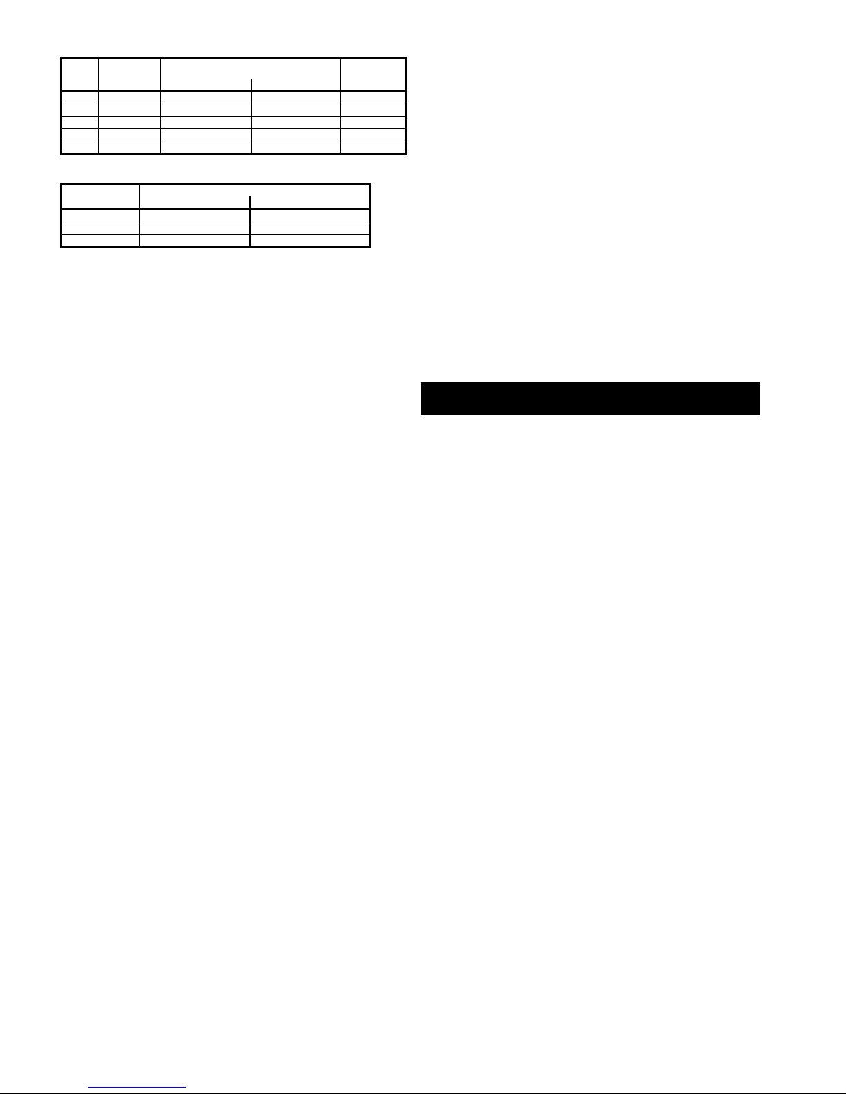
Sauna volume and min. installation distances:
Output Sauna volume Min. distance from side wall (in.)
Minimumceiling
height
kW min/m axcu.ft. normalinstallation“X” recess installation“Y” in sauna (in.)
2,2-4,5 70-210 4 8 74
5,3 - 7 140 -320 4 8 74
6,3 - 8 175 - 440 4 8 74
10.7 320-640 6 8 74
16 586-1080 6 14 83
Sauna heater – separate control panel combinations
Heater Suitable control panel
type 240 V 1~ 208 V 3~
Deluxe7-8-11 TS30-01, CC/RB 30 TS 30-01, CC/RB 30
Deluxe16 - TS58/1RB, CC/RB 60
SE-U7-U8 CC -
Installationof separate control panels.
A separate control panel is required for the Tylö Deluxe and SE-U heaters. The control
panelmust be assembledoutside the sauna.
TS-type control panels
TS panels are thermally operated and have a patented divided output. They can either
mounted on the wall or recessed for a flush fit (fig. 12). It is essential to fit insulation
behindcontrol panelsrecesse dinto the wall. The standardlength of the capillarytube
is 73 in., but a 197 in. capilla rytube is also ava ila b le .
Installinga sensorfor a TS controlpanel (fig. 13). A=capillary tube. B=sensor
holder. C=plastic holde rfor capillarytube. D=sensor that is installed 59 in. above
floorlevel(fig. 12, not abovethe saunaheater).
Extra equipment for the TS control panel.
Locking cover in transparent plastic to fit over the control panel. Available in designs
to prevent unauthorized interferencewith time and temperaturesettings, or
temperature only.
Figs. 22, 26 Wiring diagrams.
(With sauna heater Sport - U, Supersport and Combi - U with built-in control
panels).
1=sauna heater.
Check the heater’s type identification plate to ensure that the heater is connected to
the right voltage.
Don’t forget– The installationmust be earthed!
Figs. 23, 27, 29 Wiring diagrams.
(With sauna heater Deluxe and control panel TS ).
1=sauna heater. 2=control panel. 3=relay box.
Check the heater’s type identification plate to ensure that the heater is connected to
the right voltage.
Don’t forget– The installationmust be earthed!
Remote control operation.
TS control panels use contactors for remote control operation. Please request special
wiring diagram.
CC control panels.
Instructions: included with the control panel.
Can be installed at any distance from the sauna room.
CC panels are electronically operated and are available in the following models:
CC 10-1. Manualand automatic on/off. A maximum of one hours' running time,
10 hours' pre-set time.
CC 50-1. Manualand automatic on/off. A maximum of one hours' running time,
10 hours' pre-set time.
CC 100-1. Manualand automatic on/off. A maximum of one hours' running time,
24 hours' pre-set time.
CC 100-0. Built-in weekly timer. A maximum of 12 hours' continuous running time.
Placement of the thermistor (sensor).
59 in. abovefloor level (not above the sauna heater).
The thermistor wire can be lengthenedoutside of the saunawith a partially enclosed
low-voltage cable (2-core).
The thermometer in the sauna should be placed at a height so that the temperature
correspondsexactly to the numbers displayedon the CC 50/CC 100.
Relay box (RB).
(No relay box is used for SE-U heaters).
Installed outside the sauna at anydistance from it. The relaybox may not be placed
closer than one meter from the CC 10/ CC 50/ CC 100.
Partially enclosed low-voltage cable (6-core, LiYCY).
The control cable between the CC 10/ CC 50/ CC 100 and the relay box or SE-U
heater must be a partially enclosed low-voltage cable (6-core, LiYCY). Connect the
shieldin gcable to plinth 12 in the CC-panel.
Lighting.
(Not CC 10)
Connect the lighting according to the wiring diagram.
Remotecontro lope ra ti on.
CC control panels are already prepared for remote-control operation from one or more
locatio ns .
Option: externalon/off-switch(instan ta n e ous).
Can be placed at any distance from the sauna. Connected with a low-voltage cable to
the CC 10/ CC 50/ CC 100 – see the wiring diagram. If there are several external
on/offswitches, theyshould be parallel-connected.
Connection to a central computer.
The control panel can alsobe connected to a central computer, which givesa brief
impulse (closure)betweenplinths 19 and 20 in the CC 10/ CC 50/ CC 100. The
maximum permitted connection time for the sauna is 12 hours.
An instruction guide is included with the control panel.
Figs. 24, 25, 28, Wiring diagrams.
(With sauna heater Deluxe and SE-U and control panel CC ).
1=sauna heater. 2=thermistor (sensor). 3=control panel. 4=external on/off switch
(if any). 5=relay box.
Check the heater’s type identification plate to ensure that the heater is connected to
the right voltage. Don’t forget – The installatio nmust be earthed!
Unusual voltages or number of phases.
Beforeconnecting the heater to a different voltage or number of phasesthan those
described in the wiring diagram, contact Tylö Customer Service.
Building Instructions
The importance of correct sauna ventilation.
Incorrect sauna ventilation can result in hot floors and benches, scorched walls and
ceilings (the temperature limit control is triggered)! So we do urge you to follow our
instructionsfor saunaventilatio ncarefully.
Adjust the air outlet to evacuate8-10.5 cubic yards. of air per person,per hour, when
the sauna is in operation.
Mechanical saunaventilation is not to be recommended, as the forced air supply can
causea fire haza rdthrough the woode npanellingdrying out.
Fig. 7. Sauna heater and door on the same wall.
The “air circulation” created by the door should work together with the hot air generated by
thehea te r.To facilitatethis, the heate rshould be placedon the same wall as the door(If
ex ce ptio n a lcircumstance srequirethe heaterto be fitted to a side wall, makesure it is
locate din closeproximityto the wall with thedoor).
Fig. 14. Inlet vent always directly below the heater.
The inlet vent should be driven straight through the wall directly below the center of the
heater.The cross-section of the vent for a family sauna is approx. 19 sq.in., forlarger
saunasapprox. 46 sq.in. If possible, it is an advantageto have a shower on the other
side of the wall. A flap valve may be fixed to the outside of the inlet vent to prevent
waterseepinginto thewall.
Fig. 15. The outlet vent should never discharge directly into
the open air.
Position the air inlet and outlet vents as far away from one another as possible
(diagonallyopposite). The outlet vent should be locatedhigh on a wall or in the ceiling,
and should have the same cross-se ction areaas the inlet vent.
Spent air should always be led back into the same room from which it is drawn into
the sauna – it must never be discharged directly into the open air. In this way, the air
flowingfrom the sauna is continuallybeing replenis hed in theroom outside. This
ther ma lventilationmetho dalwaysworks,no matterwhetherthe press u r ein adja cent
rooms is negative or positive.
If there is a gap abovethe saunaceiling, do not seal it. To ventilate a cavity above the
sauna,drill or cut at least oneventilation hole into the cavity through the wall on which
the sauna dooris located.
Alt. A: Outlet vent through the sauna wall (seen from above). The vent is placed high
up, near the ceiling.
Alt. B: Outlet vent throughthe cavity abovethe saunaceiling (seenfrom the side).
Alt. C: Outlet vent through a drum under the ceiling in the sauna (see nfrom the side).
Theoutletduct shouldbe placed at an anglebetweentheceilingand the wall. The
drum can be built of woodenpanellingand have the sameareaas the outlet vent.
Special information for steam saunas
(Combi-U and Tylarium):
Avoid placing the outlet vent so that it is led into a part of the building which is kept
cold. This eliminatesthe risk for condens a tion.
3
Fig. 16. Recommendations for sauna construction:
A. Floorframe, cornerposts, studs, ceiling frame.
B. Batte n s ,rafte r s ,vents.
C. 3 in. mineral wool as heat insulation, approx. 3/4 in. air gap between insulation
and outer wall.
D. 1/2 in. wooden panel in walls and ceilings. There should always be at least 3 in. of
insulation behind the wooden panel; no other material, such as particle board or
plaster, may be used.
E. Bonded, non-slip plastic floor-covering, extending approx.2 in. up the walls behind
the wooden panelling.
F. Inlet vents should always be fully open. May be fitted with a shuttered vent on the
outside.
G. Outlet vent, can be fitted with a sliding hatch to adjust through-flow.
H. Benches of at least 7/8 in. thick knot-free pine (alternatively aspen, lime or
obeche).
I. Drainage channel (recommendedin public saunas). Never place a drainage
channel or drain under the saunaheater.
Fig. 17. Heater guard.
The stones and the top of the sauna heater get very hot! In order to reduce the risk of
accidental contact, Tylö alwaysrecommend that a heater guard be fixed as shown in
the sketches.
Some words of advice:
• Thereshould neverbe a drain in a sauna. However,all public saunasshould have
a drainagechannel (I, fig. 16) connected to a drain out-sidethe sauna (no drainage
channel is needed in a private sauna).
• If the sauna has a window in the door or wall, treat the lower molding with boat
varnish and seal the joint between the glass and the molding with a water-resistant
siliconeseala nt.This prevents any condens ation on the glassfrom seepingintothe
wood.
• Varnish the threshold and door handles a few times with boat varnish to maintain
the finish and simplify cleaning the sauna. Benches, decorative edging and back
supports should be oiled on both sides with Tylö sauna oil (this is particularly
important in the Tylarium).
Note: All other wood in the sauna should be untreated.
• Install floor decking only if the floor is slippery. Floor decking is impractical and
prolongs the drying time for any water spilt on the floor.
• Treat the bucket and ladle with boat varnish, or oil them with Tylö sauna oil. The
bucket will remain watertight and the wood will be beautifully preserve d.Never
leavethe woodenbucket in the saunaafter a sauna bath.
• Beforeyou enjoy your first saunabath, heat the saunaroom up to 195ºF and leave
the heater to run for about 1 hour. This will rid the room of that “new” smell.
• Clean your sauna regularly. Scrub the benches and floor with soft soap. It is a mild,
gentle detergent and leaves a pleasant fragrance.
General Information
Fig. 18. Filling the rock compartment.
Only use rocks of the dolerite type (Tylö sauna rocks), as “ordinary” rocks can damage
theunit. Fill the rock compar t me n taroun dthe elements frombottom to top, stacking
the rocks approx. 3 in. abovethe front edge at the top of the unit. Do not press the
stones into place.
Fig. 19.
Never place stones above the side air chambers. This prevents air circulation, the unit
becomes overhea tedand the temperature limit control is triggered.
Check the stone compartment at least once a year.
This is especially important for public saunas and saunas in frequentuse. Remove all
stones from the compartment. Clean any small stones, grit, gravel and chalky
deposits from the bottom of the stone compartment. Use only stones which are whole
and intact, replacing them when necessary with new dolerite stones.
Temperature limit control.
Tylö sauna heaters have a temperature limit control built into the terminal box on the
heater. This is activated automatically if there is any risk of overheating. More often
than not, the cut-off is triggered because of incorrect sauna ventilation or an incorrectly
located sauna heater. Call an expert to reset the temperature limit control.
Fig. 20. Built-in humidifier (5.3 – 8.3 kW).
Fill the built-in reservoirwith waterbeforeturning on the sauna, and you will have a
pleasantlyhumid sauna right from the start, which acceleratesand stimulates
perspiration. You can also add a few drops of sauna fragranceto the waterin the
humidifier.
Sprinkling water on the stones
Should always be done with the ladle, never with a hose or bucket.
Note: The stones must be hot.
Operating Instructions
SuperS por t, Sport-U and TS
Temperature setting.
The Roman numerals indicate a rising temperature scale. Experiment to find the
temperature that suits you best. Begin for exampleby turning the thermostat dial to
position IV. If you later find that you would prefer a higher or lower temperature, adjust
the dial up or down until you find the ideal bathing temperature for you (usually 160190°F). Once you havefound the right temperature, you can leave the dial on this
settin g .
How to use the timer.
As standard, the saunaheaters and control panelshave a 60-minute timer without
pre-set time.
Start the heaterby turning the timer knob to the position ”60”. The heaterturns off
automatically. You may turn the knob at any time back and forth to change the timing
or turn off the unit.
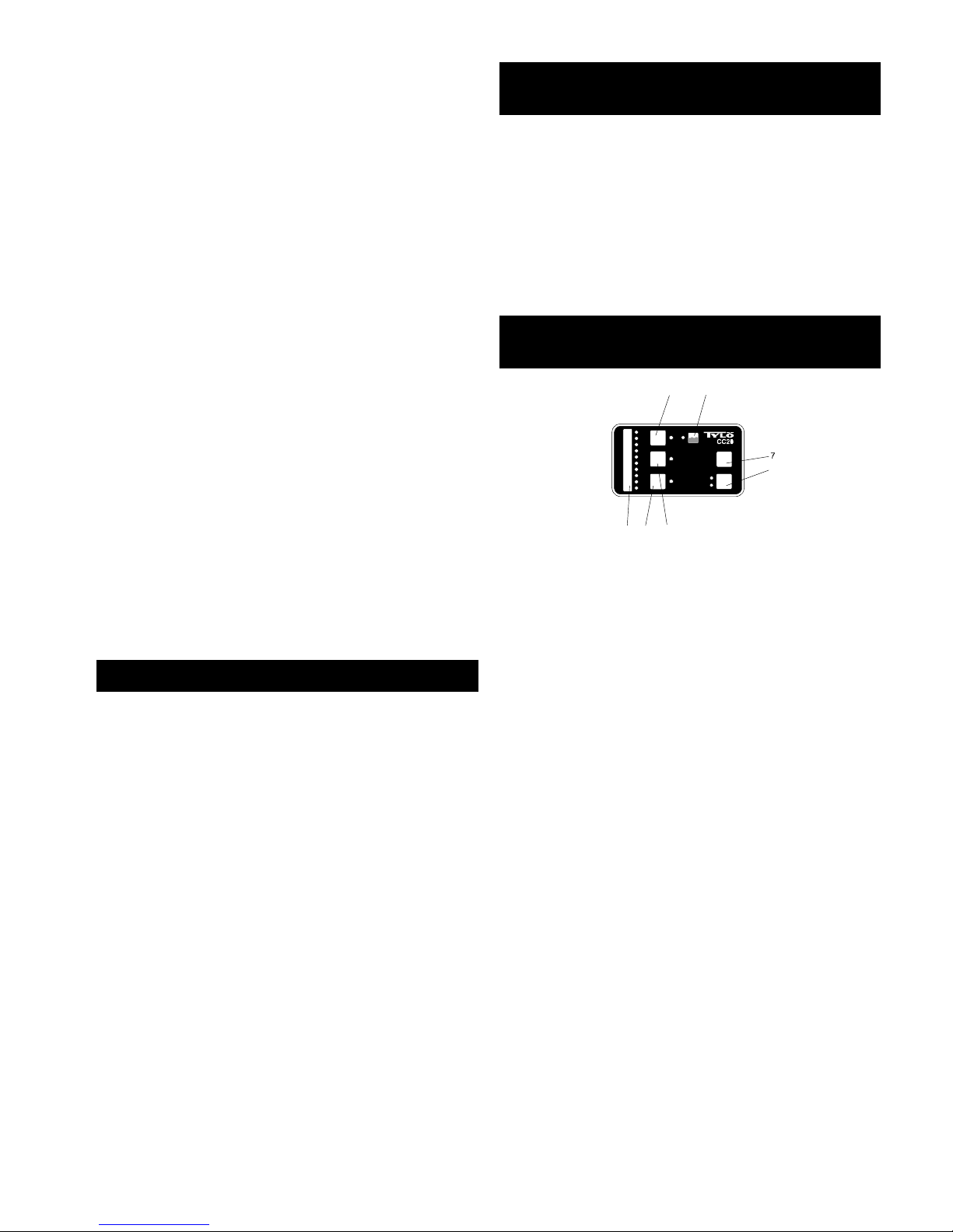
Operating Instructions
Combi-U
S
TEA
M
S
AUN
A
OFF
ON
T
IME
TEMP
R
H
%
12 3
45
6
1
0
7
6
5
1
General
Functions.
1=setting scale. 2=time settin g s .3=temperature settings. 4=humidity settings.
5=water level LED. 6=Green (on). 7=Red (off).
Main power switch.
A mains switch on the baseof the saunaheater can be used to interrupt the electricity
supply to the heater.This switch should be used if the sauna will not be used for a
longer period, such as several weeks. Note: The memory function must be reset each
time the power has been interrupted.
Temperature setting.
(Unit in ON position)
Press TEMP – the previous temperaturesetting is displayed.
The numbers indicate a rising temperature scale. Experiment to find the temperature
thatsuits youbest. Beginfor example by settin gthe temperatureat positio n4. If you
find that you would prefer a higher or lower temperature, adjust the setting until you
find the idealbathing temperature for you (usually 158-194°F for traditional dry and
wet sauna baths, 113-167°F for steam saunas and herbal saunas).
Humi d i tysetting s.
(Unit in ON position)
Press RH% – the previous humidity setting is displayed. The numbers indicate a rising
scale. Experiment to find the humidity that suits you best. Begin for exa mple by setting
the humidity at position 4. If you find that you would prefer a higher or lower humidity,
adjustthe dial until youfind the ideal humidity for you.
Note:The electroniccontro llogic’s limits the maximum humidity at given
temperatures.
Timer settings.
(Unit in OFF position)
The numbers in this case representthe pre-set time setting (= the number of hours
before the sauna heater automatically switches on). To set the timer:
Press TIME – to select the desired time, 1–10 hours.
Press Green (ON) – the timer is activated and the time LED flashesduring the pre-
set time period. The unit will start with the saunasettings that werelast used. Once
the sauna heater has been activated, it remains on for 1 hour, after which it
automatically switches off. If you want to switch it off earlier, just press Red (OFF).
Traditional sauna bathing.
Dry and wet saunas
(158-194°F, 5–30 RH%)
Press Green (ON) – only the sauna LED should be lit. The memory function
automaticallysetsthe previous temper atureand humidity(if any).
Press TEMP – if you want to change the pre-set temperature.
The built-in timer automatically switches the sauna heater off after 1 hour. If you want
to switch it off earlier, just press Red (OFF). To extend the bathing time, press Green
(ON) – only the sauna LED should be lit.

4
If you want steam production at traditional sauna bathing:
Press RH% – if you want to change the humidity setting. Setting 1 on the humidity
scale = no steam production.
Addingwater – fill until the waterlevel LED shinessteadily (a buzze rwill sound–
approx . 8 quarts). Useregulardrinking water. Steam production will ceasewhen the
water level becomes too low and the level LED starts flashing (a pulsating buzz
sounds).
The electronic control logic’s will not begin the steam production until the selected
bathing temperature is reached. The electronic control logic’s automatically adjusts
the humidity to given temperatures.
Steam sauna (Tylarium).
(113-167 °F, 20-65 RH%)
Press Green (ON) – until the steam and sauna LEDs glow steadily. The memory
function automa ti cally usesthe prev i ous settin g sfortemperatu r eandhumidity.
Press TEMP – if you want to change the temperature setting. (Setting 1 produces
steam only).
Press RH% – if you want to change the humidity setting.
Addingwater – fill until the waterlevel LED shinessteadily
(a buzzer will sound – approx. 8 quarts). Use regular drinking water. Steam
production will cease when the water level becomes too low and the level LED starts
flashing (a pulsating buzz sounds).
The built-in timer automatically switches the heater off after 1 hour, and the automatic
drying process is activated. The steam and sauna LEDs flash, even if you manually
pressed Red (OFF).
The drying cycle lasts for about 20 minutes, after which the unit switches off
completely. If you do not want to activate the drying process, press OFF again.
but if you prefer to switch the heater on immediately after bathing time before
the drying process commences, press ON – the steam and sauna LEDs will
glow steadily.
To extendthe bathing time after the heater has switched to the drying process (in
other words, when both LEDs are flashing), first press Red (OFF) and then Green
(ON). Both LEDs should then shine with a steady light.
Steam production only.
Choose settings according to above, then push TEMP –andselectsetting1on
the temperature scale.
Important!
• If the sauna has a window in the door or wall, treat the entire lower molding with
boat varnish and seal the joint between the glass and the molding with a waterresis ta ntsilicone sealant. This prev e n tsany condensa tion on the glass from
see pin ginto the joint.
• Sauna benches, decorativeedging and back supports should be oiled on both
sides with Tylö sauna oil.
• Neverscatter saunafragrancein the water inlet (A, Fig. 21) or in the herb bowl (B,
Fig. 21). This will cause a heavyfoam build-up and may trigger the temperature
limit control (L, Fig. 10). Empty the reservoir and rinse it clean of the fragrance, and
thenreset the temperatur elimit control.
• Fill the water inlet with drinking water (A, Fig. 21), until the water levelLED shines
stea dily(a buzzerwill sound– if you kee pfilling, the waterwill ove rf lo w).Steam
production will cease when the water level becomes too low and the lever LED
starts flashing (a pulsating buzz sounds). If you want more steam, add more water,
preferably hot. 1 quart of water is enough for approximately 20 minutes of steam
production.
• To prevent a build-up of calcium deposits, empty the reservoir after each sauna
bath. WARNING: The wateris HOT! Disconnect the hose(M, Fig. 10), hold it up
high and remove the plug. Lower the hoseover a suitable vessel and empty the
remainingwater.
• De-sca lethe rese rv o irregularlywith Tylö Solven tde-scalingage nt.Switch on the
heater (max humidity, min temperature)and let it run until the water in the
tank begins to boil. Switch of the heater and wait for approximately 5 minutes
Mixonebag (2.8 oz) with 4 quarts of water, pour it into the waterinlet (A, Fig. 21).
Leavethe de-scaling agent to work for approximately 1 hour, then empty and
flush the reservoir generously.
• Clean the herb bowl and fragrance cup regularly. Remove the entire top section
and rinse it under running water. Clean the bottom of the reservoir as needed.
• During any steam bath, the outlet vent should always be closed or only slightly
open.
• Open the air outlet fully after bathing. Once the automatic drying process has
finished, leavethe sauna doorslightly open to give the room a proper airing.
How to get the most out of your sauna
• Take a towel in with you to sit on. Stay inside the sauna only as long as it feels
pleasant. Go out now and then to cool off and freshen up with a quick shower.
• Show consideration for other bathers. Don’t set the temperature higher than is
pleasantfor all those using the sauna.
• Young children lovesaunas. Let them splash about in a tub of water on the flooror
the lower benches where it is somewhat cooler. But remember to keep an eye on
them at all times.
• Round off your sauna with a long, cool shower.
• Neverget dressedright after your sauna. This will only cause you to perspire.
Relax, treat yourself to a cold drink and enjoy a sensation of true well-being. Don’t
get dressed until your body has cooled down and your pores have closed once
again.
You can enjoy traditional dry and wet saunas with all Tylö
heaters.
Dry and wet saunasare bathing forms whosehistory is shrouded in the mists of time.
Thesehot baths are best enjoyed at temperaturesbetween160-190ºF.
In dry saunas, where the stones are not sprinkled with water, the relative humidity
(RH) is as low as 5–10%.
In wet saunas, when water is ladled on the hot stones from time to time, the relative
humidity rises steeply to 10–25%, and you can feelhow the quivering wavesof heat
massagetheir way into your skin. A few drops of Tylö Sauna Fragrance added to the
water poured over the stones give a pleasantly invigorating sensation, clearing nasal
cavities and helping you breathe more easily. A great way to round off any sauna is to
experience the pleasant tingling sensation when you pour a little extra water over the
stones. Wet saunas are considered by most people to be the traditional way to enjoy a
sauna,and they are the most popular too.
Important!Use ordinary drinking water. Salt-water, swimming pool or spa
water will damage the heating elements. Never hose down the heater. Devices
that provide continuous water sprinkling are not permissible.
Steam and herbal saunas(Tylarium).
A steam saunais a milder version, at only 113°F-158°F, and with a continual steam
production that maintains a high relative humidity of 20–65%.
The sauna heater constantly adapts humidity levels to the chosen setting. You can
change the humidity at any time using the RH button on the control panel. No matter
what value you have set, you can also change the humidity by reducing or increasing
the opening of the air outlet vent. To briefly increasethe humidity, you can pour a
ladlefull of water over the hot stones.
For a fragrant, refreshing herbal sauna, put some fresh or dried herbs and spices in
the herb bowl (B, Fig. 21), then relax and enjoy the revitalizing scents in a steaming
tropical climate. Test your own compositions: birch leaves, lavender, mint, spices, tea
bags (!) and other exciting scents. You can also sprinkle a few drops of Tylö Sauna
Fragrancein the scent cup (C, Fig. 21) – never in the herb bowl (B, Fig. 21) or the
water reservoir (A, Fig. 21). There are six fragrances: Eucalyptus, Mint, Menthol, Pine,
Lemon and Birch.
Tylö Sauna Fragrances can also be added to the water you splash over the stones.
Tylarium™
The unique combination of both traditional saunas and soft, mild steam baths in the
same sauna room is also called Tylarium. Use the electronic control panel to select
the kind of sauna you want, along with the desired temperature and time. Then sit
back, relax and enjoy the exquisite bath. Once in a while, add some rejuvenating
herbs or other balsam fragrances to create a new sauna sensation.
The widest range of Sauna Products
The Tylö range includes a host of fixtures and accessorie sfor a more exclusive
environment both inside and outside the sauna. For example, glass wall sections,
veranda -styleentrances with doors and windows, prefabricated sauna doorsspecially
constructed to withstand the great variationsin temperatureinside and outside the
sauna,ordinarysauna benches and thosedesigned to copewith the more demanding
environment of public saunas, comfortable back supports, decorativemolding units,
lighting and shades, fragrance dispensers and automatic water sprinklers.
In additionyou will, of course ,find saunarocks,buckets, ladles,saunafragr ances,
thermometers, hygrometers, hour glasses, woodenheadrests, vent hatches and
grilles,automatic saunahumidifiers andmuch, much more beside s .
And for outside the sauna- a comfortable bench to rest on, and a couple of elegant
deckchairs. Ask for the special brochures for Tylö Sauna Heaters/Accessories and
Sauna Rooms where you will find detailed descriptions of all these attractive fixtures.
TYLÖAB, Svarvaregatan 6, S-30250 Halmstad, Sweden.
Tel +46 35 10 00 80, Fax +46 35 102580. E-mail:info@tylo.se,Internet:www.tylo.se
© This publication manynot be reproduced, in partor in whole, without the written permission of Tylö.
Tylöreserves the right to make changes in materials, construction and design.

3
VVIVII
32 1
OFF
IV III II I
ON OFF
LIGHT
INFO
MENU
TEMP
Monday10:00:00
CC100is off
PressON to start
PressINFO for help
5
X
A
B
C
YY
Max.
40 in.
Max.
10 in.
6
A
B
Min.
3/4 in.
A = min. 8 in. (5.3 - 8.3kW)
min. 16 in. (10.7 - 16kW)
B = min. 4 in. (5.3 - 8.3kW)
min. 8 in. (10.7 - 16kW)
7
1
3
4
5
6
2
59
in.
8
1 2
4
1
2
3
4
59
in.
5
9
10
A
B
C
H
J
K
G
10½ in.
E
D
I
L
28
in.
5/8
1/8
7
in.
G
N
M

13
B
A
C
D
15
A
BC
14
A
B
C
H
E
G
10½ in.
E
I
D
11
A
B
C
H
E
G
59 in.
10½ in.
F
I
D
E
12

B
B
A
A
A
A
C
D
E
F
G
H
I
Sauna
16
17
Alt A Alt B
A = min. 4 in. (2.2 - 8 kW)
min. 8 in. (10.7 - 16 kW)
B = min. 8 in. (2.2 - 8 kW)
min. 16 in. (10.7 - 16 kW)
Min 3/4 in.
A
B
Max 8 in.
A
A
B
B
18
19
20
21
A
B
C
D
240V1~
1 = Sport-U 2/4
Super Sport 2/4
23
(4.5 kW)
DCBA1
G
~
240 V~
1 = Sport-U 2/4
Super Sport 2/4
24
(2.2 kW)
DCBA1
G
~
240 V~
115 V~
1 = Sport-U 2/4
Super Sport 2/4
22
(2.2 kW)
DCBA1
G
~
115 V~
WARNING! THIS APPLIANCE MUST BE EARTHED!
WARNING! THIS APPLIANCE MUST BE EARTHED!
WARNING! THIS APPLIANCE MUST BE EARTHED!

25
1
G
208/240V1~
1 = Supersport 7-8
Sport-U 7-8
Combi-U 7-8
L1L
2
208/240 V 1~
208/240V1~
208V3~
1 = Deluxe 16
2=TS58
3=1RB
32
2
3
1
123
208V3~
1 = Deluxe 7-8-11-16
2 = thermistor (sensor)
3 = CC10, CC50, CC100
4 = external switch
6 = RB 30, RB 60
3
42
1
6
31
208V3~
3
6
6
64
2
1
AWG 14
1 = Deluxe 7-8-11
2 = thermistor (sensor)
3 = CC10, CC50, CC100
4 = external switch
6=RB30
3
42
6
127
208/240V1~
LLGL
NABCD
115 V~
11 12 13 14 15 16
123
11 12 13 14 15 16 1718 19 20 21
3A4B 5B 6B
6
6
634
2
UVWZXY
123456
G
1
UV ZXYW
12 4563
4041 B B
AWG 14
208/240 V 1~
1 = SE-U 7, SE-U 8
2 = thermistor (sensor)
3 = CC10, CC50, CC100
4 = external switch
11
3
42
1
28
208/240V1~
134
2
AWG 14
208/240 V 1~
29
1
L1 L3L2
G
208V3~
1 = SuperSport 7-8
Sport-U 7-8
208 V 3~
1 = Deluxe 7-8-11
2 = TS 30-01
30
1
22
208V3~
208 V 3~
1 = Deluxe 7-8-11
2 = TS 30-01
ZXY
45 6
Y6
W3
X5
V2
Z4
U1
1
D
UVW
123
2
208/240V1~
26
LL
12
ABC
2
L
3
208/240 V 1~
WARNING! THIS APPLIANCE MUST BE EARTHED!
WARNING! THIS APPLIANCE MUST BE EARTHED!
WARNING! THIS APPLIANCE MUST BE EARTHED!
WARNING! THIS APPLIANCE MUST BE EARTHED!
WARNING! THIS APPLIANCE MUST BE EARTHED!
WARNING! THIS APPLIANCE MUST BE EARTHED!
WARNING! THIS APPLIANCE MUST BE EARTHED!
WARNING! THIS APPLIANCE MUST BE EARTHED!
 Loading...