

Tyco Safety Canada 193G4000W User Manual

3G4000W
3G (HSPA) WIRELESS ALARM COMMUNICATOR
INSTALLATION MANUAL V5.0
WARNING: This manual contains information on limitations regarding product use and function and information on the
limitations as to liability of the manufacturer. The entire manual should be carefully read.

Include a table of contents here.

IMPORTANT The equipment is fixed, wall-mounted and shall be installed in the position specified in these instructions. The
equipment enclosure must be fully assembled and closed, with all the necessary screws/tabs and secured to a wall before
operation. Internal wiring must be routed in a manner that prevents:
- Excessive strain on wire and on terminal connections
- Loosening of terminal; connections
- Damage of conductor insulation
WARNING: Never install this equipment during a lightning storm!
Instruct the end-user to:
- Not attempt to service this product. Opening or removing covers may expose the user to dangerous voltages or other risks. Any
servicing shall be referred to trained service persons only.
- Use authorized accessories only with this equipment.
Do not dispose of the battery in fire or water. Disposing of the battery in a fire will cause rupture and explosion. Do not dispose of
the waste battery as unsorted municipal waste. Consult your local regulations and /or laws regarding recycling with regard to this
NiMH battery pack. Doing so will help protect the environment. Some of the materials that are found within the battery could become
toxic if not disposed of properly and may affect the environment
.

Introduction
The 3G4000W is a wireless communicator that sends alarm system information to a Sur-Gard SG-System I-IP, II, III, IV or 5 Receiver
through a 3G (HSPA) or 2G (GPRS) wireless network. This wireless communicator can be used with UL/ULC Listed compatible control
units, as indicated in the manufacturer's installation instructions.
NOTE: The 3G4000W is designed to work with the Contact ID communication format as described in SIA DC-05 Standard and the SIA DC-03 standard for 300 baud.
Before completing the field installation of the alarm monitoring system, please ensure communication with the supervising central station is successful by sending
several events and getting conf i rmation that they have been rece ived.
Features
•Compatible with 4-digit or 10-digit Contact ID communication format as described in SIA DC-05
Standard and the SIA DC-03 standard for 300 bau d. Example of suitable com patible alarm panels:
DSC Models PC1864, PC1832, PC1 61 6, PC40 20.
•Simulates landline
•Switches automatically to the 3G (HSPA) or 2G (GPRS) network in the event of landline trouble (e.g.,
line down)
•Wireless Signal Strength Indicator
•Programmable Output
•Case and Wall Tamper
•Landline overvoltage prote c tion
•Quad-Band GSM/EDGE Radio
•Programmable Inputs
•3G (HSPA)/2G (GPRS) / Internet communication with Sur-G ard SG -System I-IP / II / III / IV / 5
•Panel transmission monitoring for up to four phone numbers
•Local or Remote firmware upgrade
•DLS support for status, firmware updates, and event history retrieval
•Advanced Carrier Selection
•Panel format detection
•Remote diagnostics
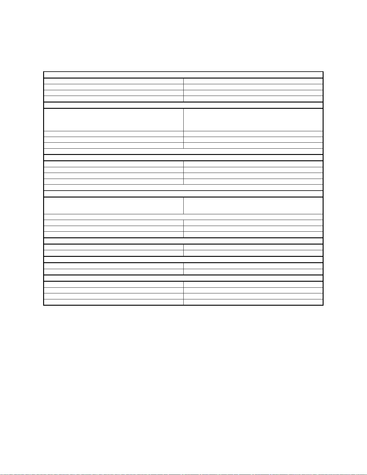
Technical Specifications
Power Supply (Sold Separately)
Input Voltage Class:
Class 2, Power Limited
Compatible External Power Adapters (2-prong):
ADP1310(W)-NA / ADP1310(W)-NAU
Power Adaptor Input
100-240V ~50/60Hz 0.4A
Power Adaptor Output
13.8V DC / 1 Ampere
Product Input Voltage and Current Draw
3G4000W Input Voltage / Input Current (Nominal)
13.8VDC/700mA (when supplied by compatible external power
supply)
Average Current
40mA*
Peak Current (no battery)
180mA*
Peak Current (with battery)
350mA*
* Plus any current draw from the 3G4000W +ve terminal if outputs are used
Battery (Sold Separately)
Battery Type
NiMH, rated 7.2V, 2.2 AH
Battery Charging Voltage (maximum)
9.1 VDC
Battery Charging Current
160 mA
Battery Standby Time
Greater than 24 hours
Note: The battery must be replaced every 3-5 years
Radio and Antenna
Supported Cellular Bands
2G Bands – GSM 850, GSM 900, DCS 1800, PCS 1900
Band 5 (850MHz), Band 8 (900 GSM)
Cellular Antenna Gain
WCDMA B5, WCDMA B8, GMS 850, GSM 900
2.5 dBi
WCDMA B1 (Tx), WCDMA B2, DCS 1800, PCS 1900
6.2 dBi
WCDMA B1 (Rx)
2.8 dBi
Environmental Specifications
Operating Temperature
0°C - 49°C (32°F - 120°F)
Humidity
93%RH Maximum (non-condensing)
Mechanical Specifications
Dimensions, Plastic Enclosure (painted)
.125 mm (W) x 220mm (H) x 31mm (D) / 4.9” x 8.7” x 1.2”
Weight (without battery)
400g / 1.2 oz
Simulated Telco Loop Specifications (TIP/RING)
On-Hook Voltage
12 VDC
Off-Hook Current
24 mA
Loop Resistance
600 Ohms
Loop Current
25 mA
The input voltage to the 3G4000W can be drawn from the UL/ULC Listed control panel or provided by an external UL/ULC Listed
power supply (with battery back-up) rated for the application (external power-limited source).
adapter)
9-14VDC/500mA (use listed, compatible control panel or power
3G Bands – FDD Band 1 (2100 MHz), Band 2 (1900PCS),

Installing the 3G4000W
Step 1 – Activate SIM card
The 3G4000W cellular alarm communicator requires a data only SIM card in 3FF Micro size. It is recommended that the SIM card
be activated with an appropriate data and billing plan prior to installing the communicator.
Step 2 - Determine the Best Signal Location
1. Remove the front cover by inserting a screwdriver into each of the slots at the bottom of the enclosure and pushing down.
2. Apply power (DC and/or battery). The 3G4000W will indicate signal strength after successfully registering on the 2G or 3G cellular
network.
Step 3 – Carrier Scanning Due To Insufficient Signal Strength
The 3G4000W will scan the surrounding cellular network and connect to the carrier. When this action is being performed, all four
LEDs will activate to show a scanning sequence. The LEDs will cycle from top to bottom and then bottom to top. This cycle will
continue until the 3G4000W is connected to a carrier with sufficient signal strength
This process can take several minutes.
The carrier scanning sequence repeats until complete.
Step 4 – Create a new account in within the Downloading Software
Open the downloading software. From the Start Page in the DLS software, click on New Account. Enter a name for the account,
and select 3G4000W v5.0 from the Panel Type dropdown box. Select SMS as the connection type, and enter the phone number of
the SIM card.
Note: It is possible to use the account template feature at this stage to quickly load cellular APN, login and password information for
the SIM card, and receiver IPs and Ports so this data doesn’t need to be manually entered for each installation.
With the cover to the enclosure removed, connect a 4 PIN PC-Link adaptor and cable to the PCLINK header on the 3G4000W
circuit board.
Step 5 – Receiver Initialization
Initially, the red LED and the blue LED are both solid and the signal strength LEDs are off.
When the LE4000 sends a request to communicate with the receiver, the top signal strength LED will begin flashing.
When the central station communicates back with the LE4000, the top signal strength LED will turn on solid.
When the LE4000 sends a request to communicate with the next receiver (if programmed), the bottom signal strength LED will
begin flashing.
When a signal is received from the central station, the bottom signal strength LED turns on solid.
If at least one receiver could not be initialized, the signal strength LED corresponding to that receiver will turn off.
Step 6 - Mount the 3G4000W
NOTE: If using a 3G4000W trim plate, snap the 3G4000S back plate onto the trim plate before mounting to the wall. If flush
mounting or using with an extension antenna, remove the provided breakaway from the trim plate prior to mounting.
1. Using the mounting holes on the LE4000 backplate, mark the four screw locations. Drill the anchor screw holes. NOTE:
Check for cable conduits and water pipes before drilling.
2. Inspect the mounting surface. Ensure that the surface is flat and will hold the wall tamper closed when mounted. Using anchor
screws (not provided), mount the cabinet to the wall. If the tamper cannot be secured it can be disabled via a programmable option.
3. Run the cables through the cable entry [13] or through the cabinet cable run knockout [15].
4. Complete the connections on the terminal blocks [12].
5. Reattach the front cover securely to the enclosure.
Step 2a – SIM Card is activated
The red LED will be on solid, the blue LED will be off and the signal strength LEDs will display the average signal
strength. In this state, the 3G4000W is registered to the cellular network.
If the signal strength is too low (bottom signal LED off or flashing), the 3G4000W will move to Step 3 and scan for carriers
with sufficient signal strength. If the 3G4000W is connected to a carrier with sufficient signal strength (minim um of bottom
signal strength LED on solid), it will move to Step 4.
Step 2b – SIM Card is not yet activated
The red LED will flash, the blue LED will be off and the signal strength LEDs will display the average signal strength.
In this state, the 3G4000W is unable to register to the cellular network because it is inactive. The signal strength indicated
is from any nearb y c el l tower (includi ng cellular towers belonging to non-roaming partners) and does not necessarily
reflect the signal strength of the intended network. The 3G4000W will remain in this state until the SIM is activated. Once
the SIM is activated, the communicator will move to Step 2a.

CONNECTING THE 3G4000W
TIP (1) / RNG (2) External Telephone Line - If the 3G4000W is being used as a back-up communicator, these terminals must be
connected directly to the incoming telephone line.
T1 (3) / R1 (4) Internal Telephone Line - These terminals must be connected to the TIP and RING of the control panel.
Zone 2 (7) Programmable Input - This terminal can be set up to trigger events. Refer to `Input' for details.
PGM2 (8) Programmable Open-collector Output - This output can be activated by programmed events. Refer to ‘Activating the
Output’ for details. The maximum current sink of each output must not exceed 50mA.
DC in + (9), DC in - (10) Device Power Supply - These terminals must be connected to a rated power supply. Once the
connections are completed, connect the battery, [12] in Figure 1) to a 7.2V, 2.2Ah battery.
NOTE: When disposing of batteries, fol l ow the instructions and prec auti ons print ed on the batteri es, and c ont act your municipal
offices for information on the disposal of used batteries.
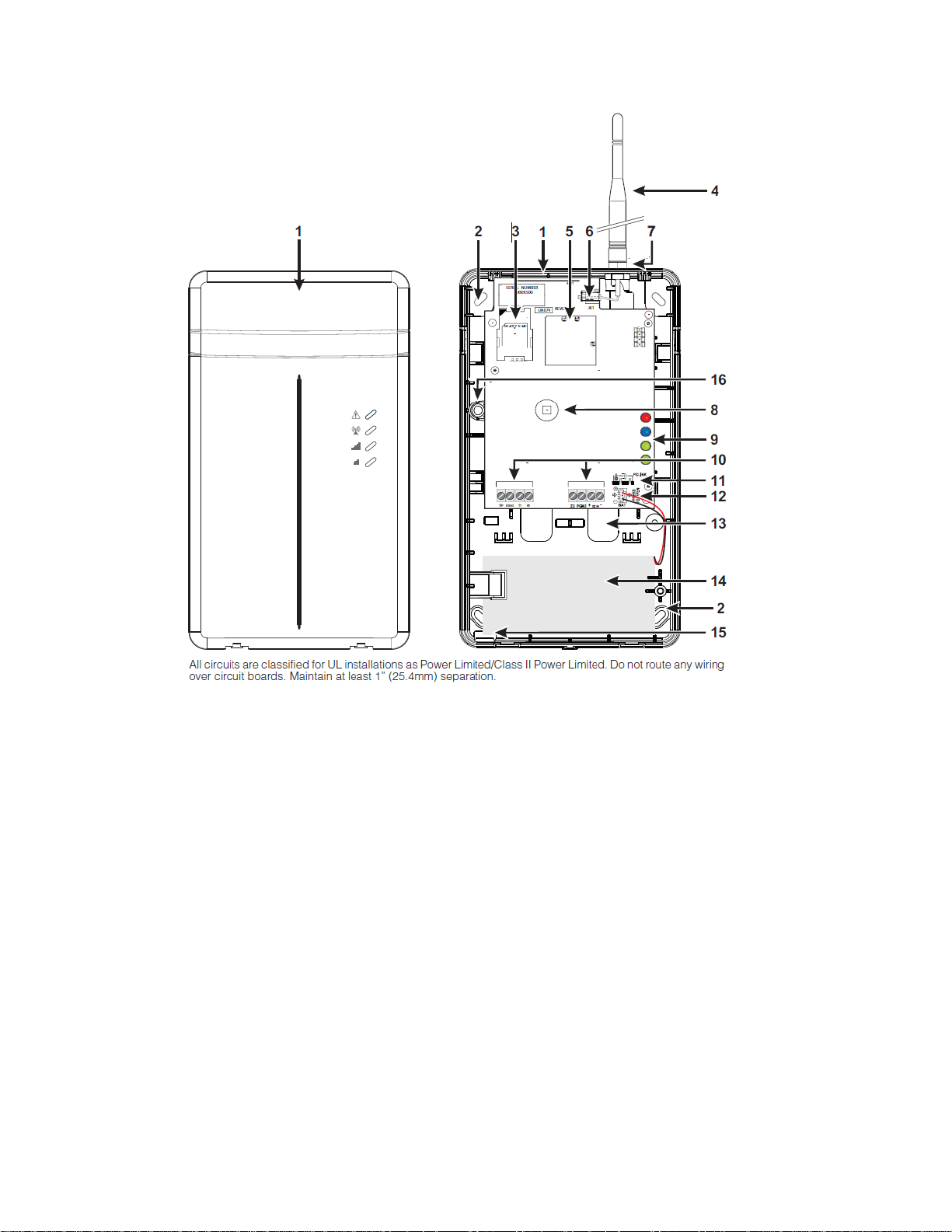
Identification of P ar ts
Table 1: Parts
Parts
1 Plastic Casing
2 Anchor Screw Holes (3mm)
3 SIM Card Holder
4 2G/3G External Antenna*
5 2G/3G (HS PA) Radio Modul e
6 Antenna Connector
7 Antenna Mounting Hardware
8 Cover Tamper Switch
9 Status LEDs
10 Terminal Blocks
11 PC-Link Connector
12 Battery Co nnector
13 Cable Entry
14 7.2V - 2.2Ah Battery
15 Cable Run Knockout
16 Wall Tamper Switch
* Use only DSC provided antenna.
This equipment (3G4000W) is fixed and shall be installed by Service Persons only (Service Person is defined as a person having
the appropriate technical training and experience necessary to be aware of hazards to which that person may be exposed in
performing a task, and of measures available to minimize the risks to that person or other persons). It shall be installed and used
within an environment that provides the pollution degree max 2, over voltages category II, in non-hazardous, indoor locations only.
This manual shall be used with the Installation Manual of the relevant alarm control panel. All instructions specified within that
manual must be observed.
Description
This 3G4000W manages transmissions to a central station and can simulate the landline in the event of trouble (e.g., landline down)
or even substitute the landline completely in areas where the 3G or 2G wireless service is provided and a landline is not available.
The 3G4000W has the capability of communicating alarm signals via the cellular data network. This capability ensures a fast,
reliable path to central stations equipped with a Sur-Gard SG-System I-IP / II / III / IV / 5 Receiver. By connecting a 3G4000W to a
control panel's standard PSTN interface, telephone based Contact ID or SIA signals are decoded and seamlessly routed through
the cellular network to any of the compatible receiver options.
The performance of the 3G4000W depends greatly on wireless network coverage. Therefore, it should not be permanently mounted
without first performing placement tests to determine the best location for reception (minimum of one green/yellow LED ON). It is
recommended that the SIM card be activated prior to performing placement test to ensure results are specific to the home network
determined by the SIM card.
Optional antenna extension kits – GS15/25/50-ANTQ (15ft/ 4.6m, 25ft/7.6m or 50ft/15.2m) and GS8-ANTP (8ft/2.4m) – are available.
The 3G4000W shall be powered from a compatible listed control unit or compatible listed power supply that complies with the
specified ratings. The power supply shall be listed for burglary applications and provide a minimum of 4 hours standby power
capabilities. An example of a suitable listed compatible control unit is the DSC Model PC1864 with an AUX output rated 11.1 -
12.6V
DC. An example of a suitable, listed power supply is DSC Model PC5204 with an AUX output rated 11.6 - 12.6VDC.

Status LEDs
Flashes
Red LED
Blue LED
1
Off
Wireless Network Trouble
2
Off
Battery Trouble
3
Off
Input Power Trouble
1
Flashing
Insufficient Signal Strength – registered on cell network
1
On
Radio / SIM trouble – Radio or SIM unresponsive
2
On
Receiver Not Available
3
On
Supervision Trouble
4
On
Wall / Cover Tamper Trouble
Off
-
No trouble conditions present
Operating Modes
The 3G4000W features two distinct operat i ng modes: Norm al Mode and Service Mode. The unit will be in Normal Mode when both
the cover and wall tamper are in a restored state. If either a cover tamper or wall tamper are present, the unit will be in Service
Mode.
Normal Mode
The 3G4000W interface has four status LEDs. The following describes the status LEDs when the communicator is in normal
operating mode (cover and wall tamper both in the restored state).
NOTE: The top two LEDs blink during the Initializing and Programming phases.
Red - This LED indicates trouble conditions.
1 Flash: Wireless Network Trouble
2 Flashes: Battery Trouble
3 Flashes: Input Power Trouble
Solid: Other Troubles (use Service Mode to view)
Blue - This LED indicates cellular radio activity. When this LED is on (solid), a phone line trouble condition exists. This LED turns on
when the interface switches to the wireless network (due to a landline trouble condition). This LED will also flash once when the
3G4000W transmits a signal and twice when the 3G4000W receives a kiss-off from the central station.
NOTE: If the 3G4000W is programmed to be the primary communicator, the blue LED will remain off but will still flash during the
signal transmission as described above.
Green/Yellow (Top) - This LED indicates signal strength and network technology. If the 3G4000W is operating in over a 2G
channel, the LED will be YELLOW. If the 3G4000W is operating over a 3G channel, the LED will be GREEN. When this LED is On,
the reception is optimal. This LED switches On only when the bottom LED is on.
Green/Yellow (Bottom) - This LED indicates signal strength and network technology. If the 3G4000W is operating in over a 2G
channel, the LED will be YELLOW. If the 3G4000W is operating over a 3G channel, the LED will be GREEN. If this LED is Off and
the Red LED is On, the Wireless Network service is unavailable (NO SERVICE). This LED flashes when the Wireless Network
reception is poor. If this LED is on, the 3G4000W is able to communicate with the 3G (HSPA) or 2G (GPRS) network.
Service Mode
To view detailed trouble information on the status LEDs, the 3G4000W must be placed in Service Mode by causing a cover or wall
tamper condition. When in Service Mode, the status LEDs will indicate the trouble condition as follows.
Trouble Conditions
 Loading...