

Tyco Safety Canada 18PG9902 Users manual
PGx902 Installation Instructions
Wireless out d oor cu rt ain pet immu ne PIR
det ect o r wit h ant i- masking
PG9902/PG8902/PG4902 O verview
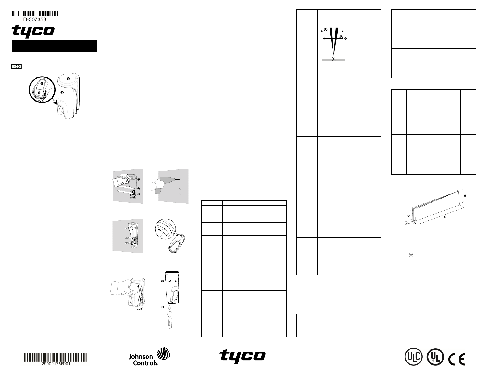
Figure 1: PGx902
1. Bracke t
2. Device
3. Indication LED
4. PIR optical window
The PGx902 is a smart wirele ss outdoor c urtain PIR
dete ctor with anti-masking supporte d by the DSC
alarm system using Powe rG two- wa y communic ation
protoc ol.
The de tec tor has the following fe atur es:
l Two channel Pyro ( patented)
l Microproc essor-controlled temperature
compensation
l White light protection
l Adjustable pet immunity selector
[no pet / pet < 9kg (20 lbs) / pet < 18 kg (40 lbs)]
l Adjustable detection sensitivity up to 8 meters
(26.2 ft)
l Advanc ed Obsidian Black Mirror™ optics
(patented)
l Target Specific Imaging™ (TSI) technology (use d
for distinction between humans and pets w eighing
up to 18 kg / 40 lb)
l True Motion Rec ognition™ a lgorithm (patented)
distinguishing be twee n the true motion of an
intruder a nd any other disturbances which may
cause fa lse alarms
l Cross-direc tion de tection ( both direc tions, left to
right, right to left)
l Smart anti-masking distinguishes be twee n masking
spray a nd ra in
l No ver tical adjustment ne eded
l Very low cur rent consumption
l Front a nd bac k tamper protection
l Supports tempe rature a nd light level re ports
according to the PowerG panel
Note : For UL installations, the dete ctor is for use with
UL listed control units only
Device set up
Warning! Do not par tially or comple tely obscur e the
dete ctor ’s f ield of view. Do not insta ll the de vice
close to tree branche s a s we athe r conditions ca n
ca use movement.
Note : Ala rms trigge re d by c onditions suc h as
wea ther, blowing le aves and branche s, or any r elated
environmenta l conditions, must be considered w hen
installing the de tector.
Warning! To comply with FCC and I SED Cana da RF
exposure compliance r equirements, locate the PIR
dete ctor at a distance of at least 20 cm from all
persons during norma l ope ra tion. The antenna s use d
for this product must not be co- loca ted or oper ate d in
conjunc tion with any other a ntenna or transmitter .
PowerSeries Neo
Note : Install a nd use the PGx902 wire less outdoor
curtain PIRdetector with anti- masking within an
environment tha t provide s pollution degr ee max 2 and
over voltage s category II in NON H AZARDOUS
LOCATI ONS. The e quipment is designe d to be
installed by qualified service pe rsons only.
Note : Install the PGx902 in ac cordance with the
Standar d f or Installation and Classifica tion of Burgla r
and Holdup Alarm Systems, UL 681.
Mo u nt ing t he PGx902
To mount the PGx902, complete the following steps:
1. Mark a nd drill at lea st two holes in the mounting
brac ket (see Figure 2 and 3).
Note : To insta ll tampe r protec tion on the
dete ctor , mark and drill one hole f or the tampe r
protection ( hole numbe r 3, Figure 2) and two
holes in the othe r available slots (number 1 a nd 2,
Figure 2).
2. Fasten the bracket to the wa ll surface with the
scre ws (se e Figure 4).
3. Insert the batter ies (se e I nserting or replacing the
batteries) and close the battery cove r.
4. Position the detector in order to c over the protected
are a by inserting the top of the detector into the
pref erred slot (se e Figure 5 and 6) .
Note : This will start the tamper self-ca librating
proc edure, whic h ca n be se en by a ye llow
blinking LED .
Note : When the devic e is inser ted into the
bracke t, it can be rota ted aga in to a more exac t
position (se e Figure 7, number 1).
5. While the LED is blinking, f asten the detector to
the bra cke t by tightening the bottom screw (see
Figure 7, number 2).
Note : If the yellow LED stops blinking bef ore the
screw is tightened a de quately, remove the
dete ctor from the brac ket and wait thre e se conds.
Now repe at the se lf- c alibr ating pr ocedur e in step
4.
Figure 2:
Mar king screw holes
Figure 4:
Faste ning t he brac ket
Figure 6: Slotting into
device
Figure 3:
Drilling scre w holes
Figure 5:
Rotation slot
Figure 7:
Drilling scre w holes
Enrollment
Refe r to the DSC panel installer guide and f ollow the
proc edure unde r the 02:ZONES/DEVICES option of
the installer me nu.
Note : For UL/ULC listed insta llations use only in
conjunc tion with UL/ULC listed c ontrol panels.
Note : When e nrolling the PGx902 detec tor to w ire less
pane ls ( WP80XX) with ver sion 19.4 or lowe r, the
dete ctor will be e nrolled a s outdoor PIR motion
dete ctor ( ID 130-xxxx ) and labele d M otion Outd. in
the panel.
Refe r to the pa ne l installation manual for the
enrollment pr oce dure. A gener al desc ription of the
proc edure is provide d in the following proce dure :
1. To ensure that the proper steps are used, re fe r to
the installation manual for the a larm system that the
device is being enrolled on.
2. From the installation menu, enter the de vice
enrollment option through the spe cified method and
select the appr opriate option to a dd the ne w device.
3. Pull the enrollment tab or insert the ba tteries to
power on the de vice and begin the auto-enrollment
proce ss.
Note : You ca n also enter ID:xxx- xxxx (the
number of the de vice that is printed on the labe l),
or press the e nroll button on the de tec tor to begin
the enrollment proc ess if the devic e does not
automatically e nroll.
4. Select the desired zone number.
5. Configure a ny device pa rameters tha t are re quired.
6. Mount a nd test the de tector. See Local diagnostic
test/Walk test for information on testing the device .
In addition, see the a larm systems installation
manual that the device is enrolled on for other test
proce dure s that ar e require d.
If the dete ctor is already enrolled, you c an c onfigure
the detector parame ters by progra mming the system,
see the alarm systems installation manua l for more
information about device parameters.
Co nfiguring t he d et ect or parameters
Modifying the device
Enter the DEVICE SETTINGS menu a nd follow the
conf igura tion instruc tions for the PGx902 dete ctor a s
desc ribe d in Ta ble 2.
Table 2: Modifying t he device
Option Configuring instructions
Alar m
LED
PIR range Selec t one of the three ra nge s,
Outdoor
anti-mask
Alar m
hours
Alar m
direction
Activa te or de activate the alarm
LED indic ation.
Optional settings: LED ON (def ault)
and LED OFF .
ac cor ding to the type of installation.
See Se tting the dete ctor range
Enable or disable the outdoor a ntimasking feature.
Optional settings: Disabled (de fa ult)
and Enabled.
Enable the motion a larms a lwa ys or
only w hen da rk ( at night).
Note :For UL/ULC insta llation, when
ena bled, the a lar m hours fe atur e for
night pr otec tion should only be used
as supple menta l prote ction to the
protection a lre ady c overing the ar ea .
Optional settings: Day and night
(defa ult) a nd Night only.
Def ine the detection direc tion. The
alarm direction f unction can reduc e
the probability of false ala rms by
more tha n half w hen the dete ctor is
installed alongside a door or gate as
the device c an diffe re ntiate betwee n
prope rty inhabita nts exiting and
potential intrude rs ente ring the
premises.
Note :Ava ilable in DSC panels
Ver sion 20.2 and highe r only.
Optional settings: Both ( default),
Left to right, Right to left.
Note:See Figure 8 for alarm
direction diagra m.
1. Right to lef t
2. Left to right
Note : Note:The r ight a nd left
directions r ef er to the installer's point
of view while obse rving the de tec tor
in its fixe d position.
VERY
HOT
> 35°C
(>95°F)
COLD
< 19°C
(<66°F)*
FREEZING
< 7°C
(<45°F)*
Disar m
ac tivity
Note : The tempe ra ture must pass beyond the
threshold for the required duration in order to
gene ra te an a larm or re store transmission.
Note : The user ca n give a cc ess to the installer
remotely e nable or disa ble the indic ation LED.
Eac h of the four te mperature alerts (VERY HOT,
COLD, FREEZING, and FREEZER) c an be
conf igure d with the settings de scr ibed in Table 3:
Def ine whe ther or not the c ontrol
pane l w ill repor t a VERYHOTalert
when the tempe ra ture rise s a bove the
thre shold va lue (def ault 35°C/95°F)
for a t lea st the dura tion spe cified in
the alert delay va lue (default 10
minutes). Alert restore will occ ur
when the tempe ra ture drops
1°C/1.8°F be low threshold for at
least the dura tion of restor e delay
(defa ult 10 minutes).
Optional settings: See Table 3.
Def ine whe ther or not the c ontrol
pane l w ill repor t a COLD alert whe n
the tempe ra ture drops below the
thre shold va lue (def ault 19°C/66°F)
for a t lea st the dura tion spe cified in
the alert delay va lue (default 10
minutes). Alert restore will occ ur
when the tempe ra ture rise s 1°C/1.8°F
above thre shold f or a t lea st the
dura tion of re stor e delay (de fa ult 10
minutes).
Optional settings: See Table 3.
Def ine whe ther or not the c ontrol
pane l w ill repor t a FREEZING a ler t
when the tempe ra ture drop below the
thre shold va lue (def ault 7°C/45°F)
for a t lea st the dura tion spe cified in
the alert delay va lue (default 10
minutes). Alert restore will occ ur
when the tempe ra ture rise s 1°C/1.8°F
above thre shold f or a t lea st the
dura tion of re stor e delay (de fa ult 10
minutes).
Optional settings: See Table 3.
Def ine whe ther or not to set the
ac tivity time during disarm.
Optional settings:
NOT Act ive (de fault), YES – no
delay, Y ES + 5 s delay, YES + 15 s
delay, Y ES + 30 s delay, YES + 1
min , Y ES + 2 min , YES + 5 min ,
YES + 10 min, YES + 20 min, YES +
60 min
Table 3: Temperat ure configuration settings
Option Configuring instructions
Threshold Displays the last sa ved threshold and
provide s the installer with the a bility
to c ha nge the value using the bac k or
next button.
©2018 Tyco Security Products
www.dsc.com
Tech. Support: 1-800-387-3630
Disable
/Enable
Aler t
delay
Restore
delay
Setting t he d et ect or ran g e
Panel Device type Me nupath
V20.2
and
higher
V19.4
and
lower
Def ines whe ther the panel will
report the alert.
Def ines the time the pane l waits
before r eporting the ale rt whe n
temperature exc eeds the de fine d
default. The ale rt delay time value s
are:
Immedia tely, 1 min, 2 min, 10 m in,
15 min, 20 min, 30 min
Def ines the time the pane l waits
before r eporting on restor ation of the
alert when the tempe ra ture re turns to
the thre shold r ange. The re stor e
delay time value s a re :
Immedia tely, 1 min, 2 min, 10 m in,
15 min, 20 min, 30 min
Table 4: Sett ing the detector range
andoptions
PGx902
S.OutCurtain
ID: 129-xxxx
TOW ER20AM
Motion Outd.
ID: 130-xxxx
>02:ZONES /
DEVICES>
>DEV ICE
SETTING S>
>PIR RANGE>
Long
Me dium
Short
>02:ZONES /
DEVICES>
>DEV ICE
SETTING S>
>PIR
SENS ITIVITY>
High
Low
One r egion
Range
8 m
5 m
3 m
8 m
3 m
8 m
Note :Range re fe rs to number 2 in Figure 9.
Figure 9: Det ection patte rn
1. 2.1 m (6.89 ft) 4. 1.9 m (6.23 ft)
2. 8 m (26.25 ft) 5. 0.25 m (0.82 f t)
3. 0.75 m (2.46 f t)
Note : The symbol signifies the dete ctor point of
view a nd the be ginning of the PIR curtain.
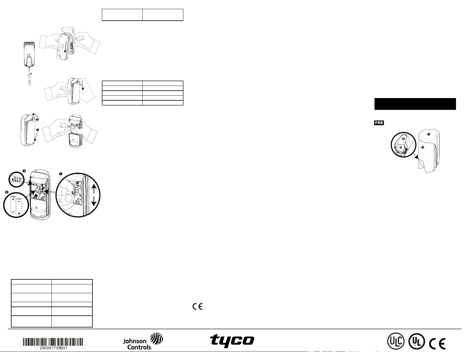
Insert in g o r r eplacin g t h e bat t eries
To inser t or re plac e the batter ies, comple te the
following steps:
1. To separate the de tector from the mounting
brac ket, unscrew the bottom scre w (see Figure 10)
and remove the detector from the bracket (see
Figure 11).
2. Open the battery cove r by pressing on the sna p
located at the top of the battery cover (see Figure
12).
3. Insert the batter ies while obse rving polarity (see
Figure 15, number 3).
Note : If the batter ies are already installed, pull
the battery tab w hile holding the batterie s in place
(see Figure 13).
4. Close the battery cove r until you hea r a click (see
Figure 14) a nd insert the device into the bra cke t
(see steps 4 and 5 in Mounting the PG x902
Note : It is rec ommended to wait about 1 minute a fte r
battery removal bef ore inse rting the ne w ba tteries.
Caution! Ther e is a risk of explosion if the batterie s
are re place d by a n incorrec t type. D ispose of use d
batteries ac cording to the manufacturer's instruc tions
and a cc ording to loca l rules a nd re gulations.
Figure 11:
Rem oving the dete ct or
from brac ket
Figure 10:
Unscrewing t he
bracket
Figure 12:
Opening t he batter y c over
Figure 14:
Closing the battery
cove r
Pet immunity, button enrollment, batter y polarity
Figure 15
1. Pet immunity selector
(1) Pet<18 kg /40 lbs
(2) Pet<9 kg /20 lbs
(3) N o func tion
(4) N o pet immunity
Note : Setting number '3' in the pet ma sk sele ctor
has no function.
2. Enrollment button
3. Batter y polarity
LED op erati on
Table 2: LED indication significance
Figure 15:
Figure 13:
Pulling the batte ry tab
LED Indication Event
Red LED blinks Stabilization ( Wa rm- up
90 sec onds)
Red LED on 0.2 seconds Ta mper open/c lose
Red LED on 2 seconds Intrude r ala rm
Yellow LED on AM detection, diagnostic
Yellow LED blinks
slowly ( 0.2 sec onds on,
30 seconds off)
mode
AM dete ction, norma l
mode
PowerSeries Neo
Yellow LED blinks
Lo cal diagno st ic t est /Walk Test
Befor e pe rmanently mounting the de vice, tempor ar ily
mount the devic e and per for m a walk te st. Perform a
walk test of the c overage area at lea st once a wee k to
ensur e that the detector is wor king c orrectly.
Afte r inser ting the batteries or c losing the battery
cove r, the detector will automa tica lly e nter a sta bility
period wher e the LED flashe s red for 90 se conds.
Whe n you walk-test the c overage ar ea , the LED lights
red each time your motion is detected, followe d by
three LED blinks. The color of the thr ee LED blinks
indicates the re ce ived signa l stre ngth. The f ollowing
table indic ate s the r ece ived signal strength.
Table 1: Walk test signal st rength indication
Back ta mper se lfca libration
LED r esponse Rec eption
3 Gre en blinks Strong
3 Ora nge blinks G ood
3 Red blinks Poor
No blinks No communication
Reliable rec eption must be confirme d. Theref ore ,
poor signal stre ngth is not a cc eptable . If you re ceive a
poor signal from the de vice , reloca te it a nd re -test
until a good or strong signal strength is re ce ived.
In wa lk-test mode, r egardless of the LED sele ction
status, the LED lights upon ever y motion detec tion.
Wa lk-test the c overage area by walking a cr oss the fa r
end of the cover age pattern in both directions. The
red LED lights each time your motion is detected
followe d by steady LED signal stre ngth indic ation.
Afte r 15 minutes the de tector automatica lly ente rs
normal mode .
Note : For UL/ULC insta llations, only strong signa l
leve ls are ac ce ptable. After installation ve rif y the
produc t f unctionality in conjunction with the
compa tible c ontrol panels:HSM2HO ST9, HS2LCDRF
(P)9, HS2ICNRF(P)9, PG9920, W S900- 19, and
WS900-29..
Note :For de tailed diagnostics te st instructions ref er to
the control pane l insta ller guide.
Temper at ur e display
For instructions on displaying the tempe ra ture and
light of z one s on the corr ec t pa nel a s measure d by the
PGx902, r efer to Conducting a Pe riodic Te st in the
wire less pane l insta ller guide .
Specificat io ns
GENERAL
Dete ctor type : Specia l two-cha nnel PIR
OPTICAL
Lens da ta: Mirror type, one cur tain mirror
Dete ctor mirror max. cove ra ge : Up to 8 m / 6°
Selec t 3 m, 5 m or 8 m (se e numbe r 2, Figure 10).
ELECTRICAL
Power supply: Type C
Interna l battery: Two 3 V lithium battery, type CR123A. For UL insta llations, use Panasonic a nd GP only
Nominal batte ry ca pacity: 1450 mAh
Battery life (typic al use) : Minimum 1 yea r. Typical
use, 3 ye ar s (not verifie d by U L)
Low ba ttery threshold: 4 V
Battery pow er te st:Performed immediately upon
battery insertion and periodica lly eve ry sever al hours.
The power supply is type C in a cc ordanc e with
EN50131-6 D ocumentation - Clause 6
Curre nt c onsumption: 30 μA a verage quiesc ent,
maximum 150 mA (dur ing transmission)
FUNCTIONAL
Alar m pe riod: 2 seconds
Pet immunity: Up to 18 kg (40 lb)
Pet c onf igura tions: N o pet / Pet < 9 kg / Pet < 18 kg
WIRELESS
Freque nc y: Europe and rest of world: 433- 434 MHz,
868-869 MHz USA: 912- 919 MHz. Only de vice s in
fre que ncy band 915 MHz a re UL/ULC listed.
Communication pr otocol: PowerG
Supervision: Signaling at 256 se cond inte rva ls
Tampe r alert: Repor ted whe n a tamper e vent oc curs
and in any subsequent me ssage, until the tamper
switch is re store d.
MOUNTING
Mounting type : W all mounting
Mounting He ight: 1.8 - 2.4 m (5.9 - 7.9 f t)
Horiz ontal Adjustment: -90° to +90°, in 10° steps
ENVIRONMENTAL
RF immunity: 0 V/m up to 1000 MHz , 10 V/m up to
2700 MHz
Operating tempe ra ture : - 35°C to 60°C ( - 31°F to
140°F) For U L / ULC installa tion, eva l-uated to 66°C
Humidity: Ave ra ge re lative humidity of up to
appr oximate ly 75% non- con-densing. For 30 days per
yea r the r ela tive humidity may vary betwe en 85% and
95% non-c on- de nsing. For UL installations: 5% to
93% with no c ondensation
Storage te mper atur es: -35°C to 60°C (-31°F to 140°F)
PHYSICAL
Size (diamete r) : 145 mm x 71 mm x 62 mm
We ight (with battery): 283 g
Color:White
Co mp at ib le r eceiver s
This devic e ca n be used with DSC pane ls that use
PowerG technology.
Note : For UL installations, the dete ctor is for use with
UL listed control units only.
Note : Only de vices oper ating in band 912-919 MHz
are UL/ULC listed.
Notice
ThePGx902 detector wasdesignedt oadhere to applicableprivacy regulationsand onlyprocesses
dataneededf ort he primaryfunctionality of thedevice.Before usingt hedetector youwillbe
askedto providec onsent with processingof thepersonaldata that the detect or maycapture.
Notet hat t hedetector records videoto securet hebest funct ionality of thedevice.The
recordings areprocessedsecurelyandautomatically erasedona periodic basis.Basedont he
locationof t hemoduleyoumay havethe obligationto issuea notice aboutusing it.
Thedatarecordedt hrough the PGx902detector are processedandmaintainedprimarilybyt he
datacontroller.D ata controller ist heentit ythat providesm onitoringservices to you. Youhave
ther ight t oenquire about your datawith t hem.For m oreinformation aboutt heir privacy
practices pleasecontact the data c ontr oller.
Form oreinformation aboutTyco privacypract ices pleasevisit ourwebsite
http:// www.tyco.com/privacy.
UL /U LC No t es
OnlymodelPG9902operatingin t hefrequencyband912-919MHz isUL/ ULC listed.ThePG9902has
beenlisted byUL for comm ercialandresidentialburglary applications andbyULC for residential
burglaryapplications inaccordancewith t herequirements in the Standards UL639 andULC- S306
for Intr usion Detection Units. For UL/ULC installationsuse thesedevice onlyin conjunctionwith
compatibleDSC wireless receivers: HSM2HOST9,HS2LCDRF(P)9, HS2ICNRF(P)9, PG9920,W S900-19,
andWS900- 29.Aft er installationverify theproduct f unct ionalityinconjunction witht he
compatiblereceiver used.
FC C C OM PLIAN C E ST A TEMENT
WARNI NG!Changes or modificat ionst ot his unit not expresslyapprovedbythe part yr esponsible
for compliancecouldvoidthe user’sauthority to operatethe equipment. Thisdevice has been
testedand foundto com plywith t helimits f ora ClassBdigital device,pursuant to Part 15of t he
FCCRules. Theselimit s aredesignedto providereasonableprotection againstharmful
interferencein residentialinstallations.Thisequipmentgeneratesuses andcan radiate radio
frequencyenergyand,if not installedandusedin accordancewith the instruct ions,may cause
harmfulinterf erence tor adio andtelevisionreception.However, there is noguaranteet hat
interferencewillnot occur in aparticular installation.I f t hisdevice doescause such
interference,which canbeverifiedby turningt hedeviceoff andon, theuser is encouragedto
eliminate theinterf erenceby oneorm ore oft hefollowing m easures:
–Re-orient or re-locate thereceivingantenna.
–I ncreaset hedistancebetweent hedevice andthe receiver.
–Connect t hedevice toan outlet ona circuit diff erent from t heonet hatsupplies power to the
receiver.
–Consult thedealer or anexperiencedradio/TV technician.
FCCID: F5318PG9902
Indu st ry C an ada St at emen t
Thisequipment complieswithFCC andISED CanadaRF radiationexposure limitsset f orthf or an
uncontrolledenvironment.This devicecomplieswith FCCRules Part15 andwith I SEDCanada
licenceexempt RSSst andard(s). Operationissubject t ot hef ollowingtwoc onditions:(1) This
devicemay not causeharmf ulinterference, and(2) thisdevicem ustacc ept any interf erence
that maybe receivedor thatm ay causeundesiredoperation.
Lepresent appareilest conform eauxCNR d'ISED Canadaapplicablesauxappareilsradioexempts
delicence.L'exploitationest autoriseeauxdeuxconditionssuivantes :(1)l'appareil nedoit pas
produirede brouillage,et (2) l'utilisateurdel'appareildoit acc epter t outbrouillage radioelectrique
subi,meme sile brouillageest susceptibled'encompromett re le fonctionnement.
Tocomply withFCCSect ion1.1310 for human exposuret oradio frequencyelectromagneticf ields
andICr equirements, implement thef ollowinginstruct ion:A distanceof at least 20cm between
theequipment andall persons shouldbe maintainedduringthe operationof the equipment. Le
dispositif doitêt re placéàune distanced'aumoins 20cm à partirde t outesles personnesau
coursdeson f onct ionnement normal.Les antennesutilisées pour ce produit nedoivent pas être
situésou exploitésc onjointementavecune autreantenneou tr ansmett eur.
IC:160A-PG9902
Theterm I C beforethe radiocertif ication number signifiest hatt he IndustryCanadat echnical
specificationswere met. This ClassB digital apparatus complieswith CanadianI CES-003.This
devicecomplieswit h RSS-247of I ndustry Canada.Operationis subject t othef ollowingtwo
conditions:(1)t his devicemay not causeinterf erence,and(2)t his devicemust accept any
interference,includinginterf erencethat mayc auseundesiredoperationof t hedevice.
Cetappareil numériquedela classeB est c onforme àlanorme N MB-003 duCanada. Cedispositif
satisfait auxexigencesd’Industrie Canada, prescrites dans ledocument CNR-247. sonutilisation
est autorisée seulement auxconditionssuivantes: (1) ilne doitpas produirede brouillageet (2)
l’utilisateur dudispositif doit êt reprêt à accepter t out brouillage radioélect riquereçu,m êmesi
cebrouillageest susceptible decompromett re lefonctionnement dudispositif.
Europe:CE/EN (EN50131-2-2 GRADE 2,CLASS I V,EN50131-6 TypeC) listedPG8902:868
MHzPG4902:433MHz. Ac cordingto EN 50131- 1,this equipment canbeappliedin installed
systemsup t oandincludingSecurity Gr ade 2,Environmental ClassIV I P55.
UK: ThePG8902 issuitablef or useinsyst ems installedto c onformt o PD6662at Grade2 and
environmentalclass IV BS8243.ThePower G peripheraldevices havetwo- waycommunication
functionality,providingadditionalbenefit s asdescribedin thet echnicalbrochure.This
functionalityhasnot beentested to comply withthe r espectivet echnicalrequirementsand
shouldtherefore be consideredoutsidethe scopeof t heproduct ’sc ertific ation.
SimplifiedEU declarationof conformity
Hereby,Tyco Safety ProductsCanada Ltd. declarest hatt heradioequipment t ype isin compliance
withDirect ive2014/53/EU.
Thefullt ext of the EU declarationof conformity is availableat t he followinginternet address:
PG4902:http://dsc.com /pdf/1710001
PG8902:http://dsc.com /pdf/1710002
FrequencybandMaximum power
433.04MHz - 434.79 MHz10m W
868.0MHz - 868.6MHz 10mW
868.7MHz - 869.2MHz 10mW
Europeansinglepoint of contact: Tyco Safety Products, Voltaweg20, 6101
XKEc ht,Net herlands.
Limite d Warra nty
DigitalSecurity Contr ols(DSC) warrants that for a periodof 12 months from the dateof
purchase, theproduct shallbef reeof defects in mat erials andworkmanshipunder normal use
andthatin f ulfilment of anybreachof suchwarranty, DSC shall,at it soption,r epairor replace
thedefect iveequipment uponreturn of t heequipment t oits repairdepot. This warrantyapplies
onlytodefect s inparts andworkmanship andnott o damageincurredin shippingor handling,or
damageduet oc auses beyondthe control of DSCsuch aslightning,excessivevoltage,m echanical
shock,water damage,or damagearisingout of abuse, alterationor improperapplicationof the
equipment.Thef oregoingwarranty shall applyonlyt ot heoriginalbuyer, andis andshall beinlieu
of anyand allother warranties,whether expressedor implied andof allother obligationsor
liabilitiesont hepart of DSC. D igitalSecurit yControls neither assumes responsibility f or,nor
authorizes anyother personpurport ingto act onit s behalf t om odify or to change thiswarranty,
nort oassume for it anyother warranty or liabilityc oncerningthis product.I n noevent shallDSC
beliable for anydirect, indirect or consequential damages,lossof anticipatedprofits, lossof
time orany otherlosses incurredbyt he buyerin connectionwitht he purchase, installationor
operationor f ailure of thisproduct. WARNI NG: D SC recommendst hatt heentir esystem be
completelyt estedona regular basis.However,despite fr equent t esting,anddue to,but not
limitedto, c riminalt amperingorelectr icaldisruption,it is possiblef ort his product t of ailto
perform as expected.I mportant I nformation:Changes/modificationsnot expresslyapprovedby
DSCc ould voidt heuser’s authority to operate this equipment.
IMPORTANT - READ CAREFULLY:DSC Soft warepurchasedwithor without Products and
Componentsis copyrightedand ispurchasedunderthe f ollowinglicense term s:This End-User
LicenseAgreement (“EULA”) is a legalagreementbetweenYou (thecom pany,individual orentity
whoacquiredt heSoft ware andanyrelated Hardware)andDigital SecurityControls, adivisionof
TycoSafety Products CanadaLtd. (“DSC”),t hemanufacturer of the integrated security systems
andthedeveloper of thesof tware andany relatedproducts or components (“HARDW ARE”)which
Youacquired.I f the DSC software product (“SOFTW AREPRODUCT” or “SOFTWARE”)is intended
to beaccompaniedby HA RDWARE, andisNOT accompaniedbynewH ARDWARE, Youmay notuse,
copyorinstall the SOFTW AREPRODUCT.The SOFTWA REPRODUCTincludescomputer soft ware,
andmayincludeassociatedmedia,printed materials, and“online” or electronic documentat ion.
EULA
IMPORTANT READ CAREFULLY:DSC Soft warepurchasedwith or without Products and
Componentsis copyrightedand ispurchasedunderthe f ollowinglicense term s:
ThisEndUser License Agreement ("EULA")is alegalagreement between You(t hec ompany,
individualor entity whoacquired theSoft wareand anyrelated Hardware)andDigital Security
Contr ols,adivisionof TycoSafety Products CanadaLt d.("DSC"),the m anufact urerof t he
integratedsecurity systems and thedeveloperof t he software andany relatedproducts or
components ("HARDWA RE")which Youacquired.
If t heDSC soft wareproduct("SOFTWA REPRODUCT" or "SOFTWARE")is intended tobe
accompaniedbyH ARDWARE, andis NOT accompaniedby newHARDW ARE, You maynot use,c opy
orinstall the SOFTWARE PRODUCT.TheSOFTW AREPRODUCT includescomputer sof tware,and
mayincludeassociatedm edia,printedm aterials,and"online" orelectronic documentation.
Anysoft wareprovidedalongwith theSOFTW ARE PRODUCT t hatis associatedwit ha separateend
userlicenseagreement islicensedto Youunderthe t ermsof that licenseagreement.
Byinstalling,copying, downloading,st oring, accessingorot herwiseusing the SOFTWA REPRODUCT,
Youagree unconditionallytobe boundbyt heterm s of this EULA ,evenif t hisEULA is deemedt o
beam odificat ionof anyprevious arrangement orc ontr act. If Youdo not agreet ot heterms of
thisEU LA, DSCis unwillingto licensethe SOFTWARE PRODUCT to You,and Youhavenor ight to use
it.
SOFTWAREPRODUCT LICENSE
TheSOFTWARE PRODUCT isprotect edbyc opyright laws andinternational copyright t reaties,as
wellasother intellectualproperty laws andtr eaties. TheSOFTWARE PRODUCT is licensed, not
sold.
1.GRAN TOF LI CENSE. ThisEULA grants You the followingrights:
(a)Software Inst allationand Use- For eachlicenseYouacquire,You mayhaveonlyonecopyof t he
SOFTWAREPRODUCT installed.
(b)Storage/Network Use- The SOFTWAREPRODUCT may not beinstalled, accessed,displayed,
run,sharedor usedconcurrently onorf rom dif ferent computers, includingaworkstat ion,
term inalor other digital electronicdevice ("Device").In other words,if You haveseveral
workstations,Youwill haveto acquirea licensefor eachworkstation wherethe SOFTWARE willbe
used.
(c)BackupCopy- You maymake backupcopiesof t heSOFTWARE PRODUCT, butYou mayonlyhave
onecopyper license installedat anygiventim e. Youm ayuset heback upcopysolelyfor archival
purposes.Exceptas expresslyprovidedint hisEULA, Youm aynot otherwisemake copiesof t he
SOFTWAREPRODUCT, includingthe printed materials accompanyingtheSOFTW ARE.
2.DESCRIPTION OF OTHER RIG HTS AND LI MITATI ONS
(a)Limitat ionson ReverseEngineering, DecompilationandDisassembly - Youmay not reverse
engineer, decompile,or disassemblet he SOFTWAREPRODUCT,except andonlyt ot he extent that
suchactivity is expresslypermit tedby applicablelawnotwithstandingt hislimitation.You may
notm akeany changes ormodificat ionst o t heSoftware,wit hout t hewritten permissionof an
offic erof D SC.Youm aynotrem ove anyproprietary notices, marksor labelsfrom t heSoftware
Product. You shallinstitute reasonable measuresto ensurecompliance with the term sand
conditions oft hisEULA.
(b)Separationof Components - TheSOFTW AREPRODU CTis licensed asa singleproduct. I ts
component parts may notbeseparatedf or useonm ore thanoneH ARDWARE unit.
(c)SingleI NTEGRATED PRODUCT - I f Youacquiredt his SOFTWARE withH ARDWA RE,then the
SOFTWAREPRODUCT is licensedwith t heHARDW ARE as asingleintegrated product. I nt hiscase,
theSOFTW AREPRODUCT m ayonly beusedwith theH ARDWARE as set f orth int hisEULA.
(d)Rental - Youmay not rent, leaseor lendthe SOFTWAREPRODUCT. Youm aynot makeit
availablet oothers or postit onaserver or websit e.
(e)Software Product Transfer - Youmay t ransferall of Your rights under this EULA onlyas part
of apermanentsale or transfer of t heHARDW ARE,provided You retain nocopies,Youtr ansfer
allof the SOFTWA REPRODUCT(includingall component parts, t hemedia andprinted materials,
anyupgrades andthis EULA),and providedt herecipient agrees tot he term sof t hisEULA. I f the
SOFTWAREPRODUCT is anupgrade, anytransfer must alsoincludeallprior versionsof t he
SOFTWAREPRODUCT.
(f) Termination- Wit hout prejudiceto anyot herrights, DSC mayt erminate this EULA if You fail
to complywit hthet erms andconditions of thisEULA . In such event, Youmust destroyall copies
of theSOFTWA REPRODUCT andall of itsc omponent parts.
(g)Trademarks- This EULA does notgrant Youany rightsin connectionwithany tr ademarks or
servicemarks of DSC or its suppliers.
3.COPYRIG HT
Allt itle andintellectualproperty rights in andt ot heSOFTWARE PRODUCT (includingbut not
limitedto anyimages,photographs,and text incorporatedinto t heSOFTWARE PRODUCT),t he
accompanyingprintedm aterials,andanyc opiesof theSOFTW ARE PRODUCT,are ownedbyD SC or
its suppliers.Youmay not copyt heprintedm aterialsacc ompanyingt he SOFTWARE PRODUCT.A ll
tit leandintellectualproperty rightsin andto the content whichmay beacc essed throughuseof
theSOFTW AREPRODUCT aret heproperty of t herespectivecontent owner andmaybe protected
byapplicablecopyright or other intellectualproperty laws andtreaties. This EULAgrants Youno
rightst o usesuchcontent. All r ights not expresslygranted undert his EULA are reservedbyDSC
anditssuppliers.
4.EXPORTRESTRICTION S
Youagree that Youwill notexport or re exportt he SOFTWARE PRODUCT toanycountry, person,
orentit y subjectt o Canadianexport restric tions.
5.CHOI CEOF LAW :This Software LicenseAgreement is governedbythe lawsof the Provinceof
Ontario,Canada.
6.ARBITRATI ON
Alldisputes arisinginconnectionwith t hisAgreement shallbedeterm inedbyf inalandbinding
arbitrationin accordance with theA rbitrationA ct, andthe partiesagreet obe boundby t he
arbitrator's decision.Theplace of arbitrationshall beToronto,Canada,andt helanguageof t he
arbitrationshallbe English.
7.LIMI TED WA RRANTY
©2018 Tyco Security Products
www.dsc.com
Tech. Support: 1-800-387-3630
(a)NO WARRANTY
DSCPROVIDES THE SOFTWARE "AS I S"W ITHOU T WARRANTY. DSCD OES NOT WARRANT THA T
THE SOFTWARE WI LLMEET YOURREQUI REMENTS O RTHAT OPERATION OF THE SOFTWARE WI LL
BEUN INTERRUPTEDO R ERROR-FREE.
(b)CHANG ES IN OPERATING ENVIRONMENT
DSCshall notber esponsiblef or problems causedby changesin theoperatingcharacterist ics of
theH ARDWARE, or for problems intheint eractionof t heSOFTWARE PRODUCT withnon-DSCSOFTWAREor HA RDWARE PRODUCTS.
(c)LI MITATI ON OFLI ABILI TY;WA RRANTYREFLECTS ALLOCATION OF RISK
IN AN YEVENT, IF AN Y STATUTEI MPLIES WARRANTI ESOR CONDI TION SN OTSTATED I NTH IS
LICENSEA GREEMENT,DSC'S ENTI RE LIABILI TYU NDERA NY PROVISION OF THI S LICENSE
AGREEMENT SHALL BELIMI TED TO TH EGREATER OF THEA MOUNT ACTUA LLYPAI D BYYOU TO
LICENSETH E SOFTWARE PRODUCTAN D FI VECANAD IAN DOLLA RS(CAD$5.00).BECAUSE SOME
JURISD ICTION SDO NOT A LLOWTHE EXCLUSION ORLI MITATI ON OFLI ABILI TYFOR
CONSEQUENTI ALO RIN CIDENTA LD AMAGES, THE A BOVELIMITATI ON MAY NO TAPPLY TOYOU.
(d)DI SCLAIMEROF WARRANTI ES
THIS WA RRANTY CONTAI NS THE ENTIRE W ARRANTYA ND SHALL BE IN LIEU OF ANY AN D ALL
OTHERWA RRANTIES, WHETHER EXPRESSEDOR IMPLIED (I NCLUDI NG ALL I MPLIED
WARRANTI ES OFMERCHANTABI LITY ORFI TNESS FORA PARTICULA RPURPOSE)A ND OF ALL
OTHEROBLIG ATION SOR LIA BILITI ESON TH E PARTOF DSC. DSCMAK ES NO OTHER
WARRANTI ES.D SCNEI THER ASSUMES NORA UTHORIZES ANY OTH ERPERSON PURPORTING TO
ACTON I TS BEHALFTO MODI FYOR TO CHANG E THIS WA RRANTY, NOR TO ASSUME FOR IT ANY
OTHERWA RRANTYOR LIA BILITY CONCERNING THI S SOFTWA REPRODUCT.
(e)EXCLUSIVEREMEDY AN DLI MITATI ON OFW ARRANTY
UND ERNO CIRCUMSTANCES SHALL DSC BELI ABLE FORAN Y SPECIAL, INCI DENTAL,
CONSEQUENTI ALO RIN DIRECT DAMAG ES BASED UPON BREACH OFW ARRANTY,BREACH OF
CONTRACT,NEG LIGEN CE,STRICTLIA BILITY, ORA NYOTH ERLEG ALTHEORY. SUCH D AMAGES
IN CLUDE,BUT ARE NOT LI MITEDTO, LOSSOF PROFITS, LOSSO FTHE SOFTWA REPRODUCT OR
ANY ASSOCIATED EQU IPMENT,COST OF CAPITAL, COSTOF SU BSTITUTE ORREPLACEMENT
EQUI PMENT, FACILI TIES ORSERVICES,D OWN TI ME,PURCHASERS TIME, THE CLAIMS OaFTH IRD
PARTIES,IN CLUDIN G CUSTOMERS, AND IN JURY TOPROPERTY.
WARNI NG:D SC recommendst hatt he entire systembe completelyt estedon aregular basis.
However,despite fr equent testing, anddue to,but not limited to,cr iminalt amperingor
electrical disruption,it is possiblef or t hisSOFTWARE PRODUCT tof ail to perf orm asexpected.
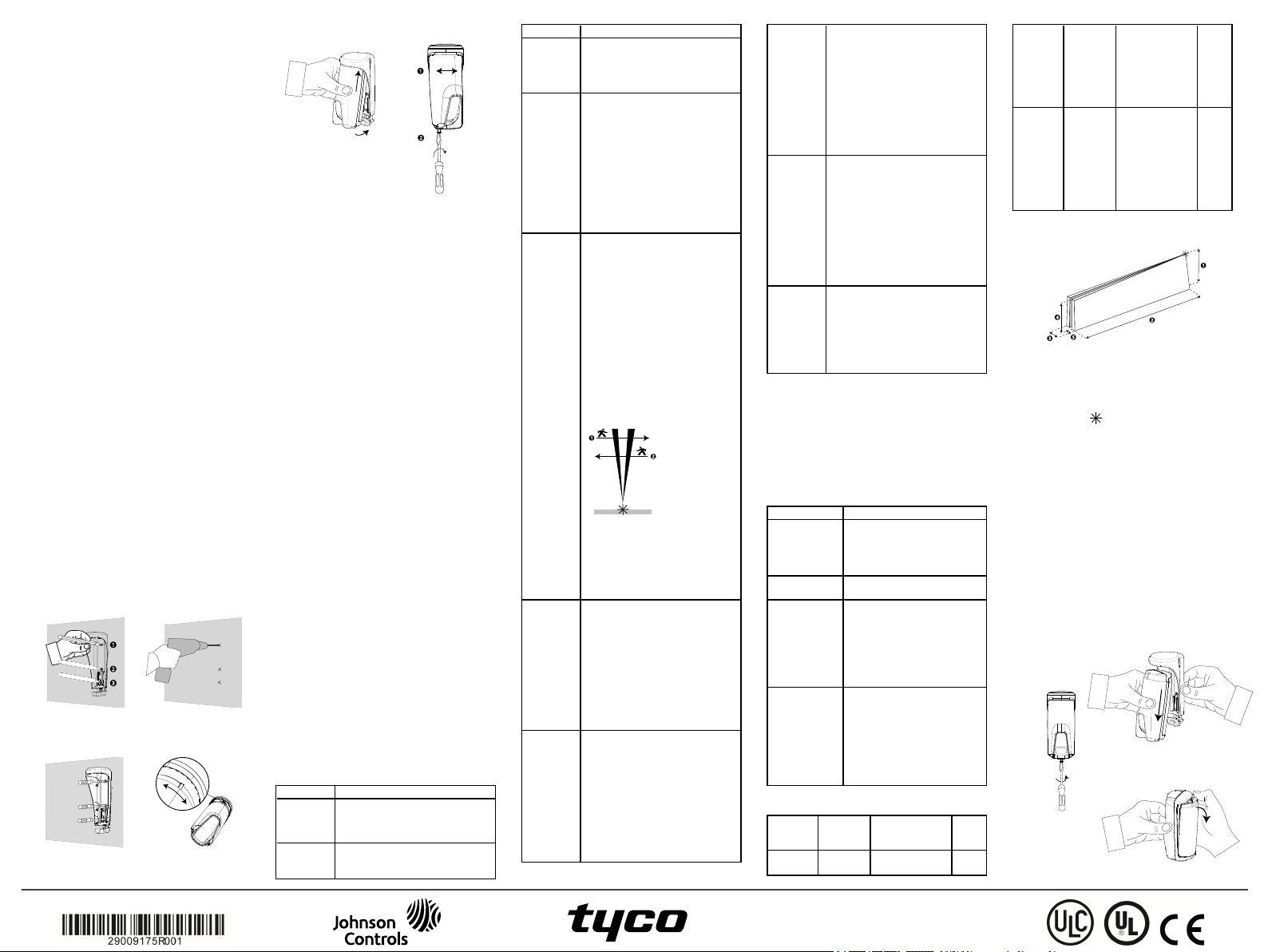
PGx902 Instructions d'installation
Dét ect eu r PIR san s f il in t elligent à rid eau et ant i- masq uage po ur l' ext érieur
PG9902/PG8902/PG4902 Présen t at ion
1. Support
2. Dispositif
3. LED
4. PIR
Le PGx902 e st un déte cte ur PIR sa ns fil intelligent à
rideau et a nti-masqua ge pour l'extérieur, compa tible
ave c le système d'ala rme DSC grâ ce au protocole de
communication bidire ctionnel PowerG.
Le dé tec teur pr ésente les c ar actéristiques suivantes:
l Capacité pyroélectrique 2 canaux (bre vetée)
l Compensation de température contrôlée par
microproc esseur. La chambre noire scellée est
protégée de la lumière blanc he
l Trois options de non-dé clenchement par les
animaux (Aucun a nimal / Animal < 9 kg / Animal
< 18kg)
l Sensibilité de détec tion jusqu'à 8 mètres
l Système optique Advanc ed Obsidian Black
Mirror™ (bre veté)
l La technologie Ta rget Specific Imaging™ (TSI)
fait la distinction entre les individus et les animaux
pesant jusqu'à 18kg
l L'algorithme avancé True Motion Recognition™
(bre veté) per met de faire la distinction entre les
mouvements réels d'un intrus et toute autre
perturbation susceptible de déc lencher de fausses
alertes
l Détection transversale
l L'anti-masquage fait la différence entre la pluie e t
un masquage par bombe de peinture
l Aucun r églage vertical n'est nécessaire
l Consommation électrique extrêmement fa ible
l Autoprotection a vant et arr ière
l L'appareil est compatible avec la fonction de
signalement du nivea u de température et de
lumière à la c entra le PowerG
Figure 1: PGx902
Rem arque: Pour les insta llations cer tifiée s, le
déte cte ur ne doit êtr e utilisé qu'ave c des unités de
contrôle ce rtifié es UL.
Configuration de l'Appareil
Caution! N 'obstruez pas, totale ment ou par tielleme nt,
le champ de vision du dé tec teur. Ne l'installez pa s à
proximité de br anche s d'arbre que le vent pour ra it
agiter.
Caution! Pour des ra isons de c onformité a ux normes
d'exposition aux fré que nces r adio FCC et ISED
Canada, le dé tec teur PIR doit être distant d'au moins
20 cm de toute personne , e n conditions de
fonc tionneme nt norma les. Les a ntennes utilisées pour
ce produit ne doivent pas être positionnées dans un
même e spac e, ni utilisée s avec une a utre antenne ou
émetteur.
Rem arque: Le détecteur PIR sans fil à ride au et a ntimasqua ge pour l'extérie ur PGx902 sera installé et
utilisé da ns un ENV IRONNEMEN T NON
DANGEREUX où le nivea u de pollution e st infé rie ur
à 2 e t où il est exposé à des tensions de ca tégor ie II.
L'équipe ment e st c onç u pour être insta llé par du
personnel de ma intena nce qualifié unique ment.
Rem arque: Le PGx902 ser a installé c onformément à
la norme UL 681, Standar d for Installations a nd
Classifications of bur glar a nd Holdup Alarm Systems.
Mo n tage d u PGx902
1. Marque z e t percez au moins de ux trous dans le
support de montage (voir Figure 2 et 3).
Note : Si vous installez l'autoprotection sur le
déte cte ur, marquez e t per cez un tr ou pour
l'autoprote ction(trou numéro 2, Figure 2)et deux
trous dans les autres enc oches disponibles
(numéro 1 et 3, Figure 2).
2. Fixez le support à la surface du mur ave c les vis
(voir Figure 4) .
3. Insérez les piles (voir Insertion ou rem placem ent
des piles) e t refermez le capot.
4. Choisissez l'emplacement le plus pertinent pour le
détec teur de manière à ce qu'il couvre la z one à
protéger, et insérez la partie supé rieur e du
détec teur dans l'encoc he a déqua te (voir Figure 5).
Rem arque: Ceci a pour ef fe t de dé mar re r la
proc édure d'auto éta lonnage de l'autoprotection,
signalée par l'illumination d'un voyant jaune
clignotant.
5. Pendant que le voyant c lignote, fixez le dé tecteur
au support e n re sserr ant la vis infé rieure(voir
Figure 6).
Rem arque: Si le voya nt ja une a rr ête de clignoter
ava nt que vous n'ayez e u le te mps de serrer la vis,
retirez le déte cteur du suppor t e t attendez trois
sec ondes. Répé tez la procédure d'auto é talonna ge
indiquée à l'étape 4.
Figure 2:
Mar quage des t rous des
vis
Figure 4: Figure 5:
Fixation du support
Figure 3:
Per çage des tr ous des
vis
Encoche de rotat ion
PowerSeries Neo
Figure 6:
Enclenchem ent dans
l'appareil
E
nregistrement
Consultez le Guide de l'installa teur de la ce ntra le DSC
et suivez la procé dure indiquée pour l'option
02:ZONES/APPAREILSdu Menu Installate ur.
Rem arque: Dans le c as d'installations c onf orme s
UL/ULC, utilisez unique ment le détecteur avec des
ce ntra les c ertifié es UL/ULC.
Rem arque: Lors de l’enr egistreme nt d'un dé tec teur
PGx902 dans les c entrales sa ns fil (W P80XX) doté es
de la version 19.4 ou inférieure, ce lui-ci est e nregistré
en tant que détec teur de mouveme nts PIR pour
l'extérieur (ID 130- xxxx) e t identifié pa r IR
extér ieur dans la ce ntra le.
Pour des informations détaillées sur la pr océdur e
d'enre gistre ment, consultez le ma nue l d'installation de
la centrale. Une description géné ra le de la procé dure
est indiquée dans le ta bleau suivant :
1. Consultez le manue l d'installation du système
d'alarme dans leque l l'appare il e st enregistré a fin
de suivre la procédur e a déqua te.
2. Utilisez la méthode préconisée pour a cc éde r à
l'option d'enregistre ment de l'appareil e t
sélectionnez l'option c orre spondante pour ajouter
un nouvel appare il.
3. Tirez sur la languette d'enregistrement ou insére z
les piles pour mettre l'appar eil sous tension et
lance r la procé dure d'auto-enregistrement.
Rem arque: Vous pouvez aussi entr er l'ID:xxxxxxx (numé ro de l'appar eil imprimé sur
l'étiquette), ou appuyer sur le bouton
d'enre gistre ment du dé tec teur pour déma rr er la
proc édure d'enr egistreme nt, si l'appa reil ne
s'enre gistre pas a utomatique ment.
4. Sélectionnez le Numéro de zone voulu.
5. Configurez les paramètres né cessaires de
l'appareil.
6. Montez e t testez le détecteur. Pour savoir comment
tester l'appareil, c onsultez la section Test de
déplace ment. Consultez également le manuel
d'installation des systèmes d'alarme dans lesquels
l'appareil e st enre gistré pour con-naître la
procé dure à suivre .
Si le dé tecteur e st déjà enr egistré, vous pouvez configurer ses paramètres en pr ogrammant le système.
Pour plus d'in-formations sur les pa ramètres de
l'appar eil, c onsultez le manuel d'installation des
systèmes d'alarme.
Co nfiguration des p aram èt res du détecteur
Modification de l'appareil
Allez dans le me nu Param.D.L'appar. e t suivez le s
instructions de configur ation du détecteur PGx902
indiquée s da ns le Ta blea u 2.
Tableau2: M odificat ion de l'appareil
Option Instruct ions de configuration
LED
ALRM
CouvertureIRSélec tionnez une des trois por tée s,
Active z ou dé sac tivez le voyant
d'alar me.
Options: LED ON (par dé faut) et
LED OFF.
en fonction du type d'installa tion.
Voir Dé finition de la po rtée du
Figure 7:
Fer me ture du support
Antimasque
exté rieur
Période A ctive z les alarmes de mouve ment
Dire ction
de l'ala rme
TRES
CHAUD
> 35°C
FROID
< 19°C
déte cte ur
Active z ou dé sac tivez la
fonc tionnalité d'anti-ma sque
exté rieur.
Options: Désac tivé (par défaut) et
Act ivé.
en pe rma nence ou unique ment
lorsqu'il fa it noir (la nuit).
Note :Rema rque: Pour le s
installations cer tifiée s UL /ULC,
lorsqu'elle est activée et de stinée à
assurer une prote ction noctur ne, la
fonc tionnalité Période doit
seulement ê tre utilisée en
complément de la pr otec tion dé jà
prévue pour la zone.
Options: Jour e t Nuit ( par déf aut)
et Nuit.
Déf inissez la direction de la
déte ction. La f onction de direc tion
de l'ala rme peut diviser par deux,
voire plus, le risque de fa usses
alarmes lorsque le détec teur est
installé à c ôté d'une porte ou d'un
portail, ca r l'appar eil fait la
diffé renc e entre les réside nts qui
sortent du bâ timent e t les intrus qui
pénè tre nt da ns les loca ux.
Rem arque: Disponible uniquement
sur les c entr ale s DSC Version 20.2
et supé rieur.
Options de paramétrage : Les deux
(par défaut), De gauche à droite ,
De droite à gauche.
Rem arque:Voir Figure 8 pour un
sché ma du sens de l'alarme.
Figure 8: Déte ction de la dire ction
1. De droite à gauche
2. De gauc he à droite
Rem arque:Les dire ctions depuis la
gauc he e t depuis la dr oite
s'entendent pa r rapport à la position
de l'installate ur lorsqu'il obser ve le
déte cte ur une fois f ixé.
Indique z si la centrale enver ra une
alerte TRS CHAUD lorsque la
température dépassera la va leur
seuil (par défaut 35°C) pendant au
moins la duré e indiqué e par le délai
d'alerte (10 minutes par défaut).
L'aler te ser a rétablie lor sque la
température re passe ra e n-de ssous
du seuil pe nda nt a u moins la duré e
du délai de rétablissement (10
minutes pa r défaut).
Options: Voir Tableau 3.
Indique z si la centrale enver ra une
alerte FROID lor sque la
température desc endra sous la
vale ur seuil ( par déf aut 19°C)
penda nt a u moins la dur ée du délai
d'alerte (10 minutes par défaut).
L'aler te ser a rétablie lor sque la
température dépassera le se uil d'1°C
penda nt a u moins la dur ée du délai
de ré tablissem ent (10 minutes par
défaut) .
Options: Voir Tableau 3.
TRES
FROID
< 7°C
CONGELATION
> -10°C
Désarmer
l'activ
Pour déc lenc he r une alarme ou un signal de
rétablissement, la température doit dépasse r le seuil
penda nt la duré e r equise.
L'utilisateur peut ac corde r un ac cès à l'installa teur
afin qu'il puisse ac tiver ou dé sactive r à distance le
voyant d'indica tion.
Chacune des quatre alertes de tempéra ture (TRÈS
CHAUD, FROID, TRÈS FROID, et CONGELATR)
peut être c onfigurée a vec les pa ra mètres déc rits dans
le Ta blea u 3:
Tableau 3: Paramèt re s de c onfigurat ion de la
Option Instructions de conf igura tion
Seuil Aff iche le dernier se uil
Désactiver
/Activer
Délai d'alerte Définit le temps pendant leque l
Délai de
ré tablissement
Déf initi on d e la po rt ée du détecteur
Tableau4: Définition de la portée du détec te ur
Centrale Type
V20.2 et
supér ieur
Indique z si la centrale enver ra une
alerte TRÈS FROID lorsque la
température desc endra sous la
vale ur seuil ( par déf aut 7°C)
penda nt a u moins la dur ée du délai
d'alerte (10 minutes par défaut).
L'aler te ser a rétablie lor sque la
température dépassera le se uil d'1°C
penda nt a u moins la dur ée du délai
de ré tablissem ent (10 minutes par
défaut) .
Options: Voir Tableau 3.
Indique z si la centrale enver ra une
alerte CONGELATR lorsque la
température dépassera la va leur
seuil (par défaut -10°C) pe ndant au
moins la duré e du délai d'alerte (30
minutes pa r défaut). L'alerte se ra
rétablie lorsque la tempé ra ture
repasse ra e n-de ssous du se uil
penda nt a u moins la dur ée du délai
de ré tablissem ent (30 minutes par
défaut) .
Options: Voir Tableau 3.
Déf inissez un dé lai d'ac tivité pour le
désa rme ment.
Désactivée (par dé fa ut), OUI –
aucun délai, OUI + délai de 5 s,
OUI + délai de 15 s, OUI + délai de
30 s, OUI + 1 m in , OUI + 2 min ,
OUI + 5 m in , OUI + 10 min, OUI
+ 20 m in, OUI + 60 min
tempér ature
enregistré e t per met à
l'installateur de modifier la
vale ur à l'aide du bouton
Préc édent ou Suiva nt.
Déf init si la c entrale signa ler a
l'alerte.
la centrale attend ava nt de
signaler l'alerte lor sque la
température dépasse la valeur
par défaut définie. Les valeurs
de délai d'alerte sont:
Immédia teme nt, 1 min, 2 min,
10 min, 15 min, 20 min, 30 min
Déf init le temps pendant le que l
la centrale attend ava nt de
proc éder à un signale ment
après ré tablissement lorsque la
température re vient dans la
plage de seuil. Le s valeurs de
délai de r établissement sont:
Immédia teme nt, 1 min, 2 min,
10 min, 15 min, 20 min, 30 min
d'appareil
PGx902
Emplacement /
options du me nu
>02:ZONE/
APPAR>
Plage
©2018 Tyco Security Products
www.dsc.com
Tech. Support: 1-800-387-3630
Rideau
extér ieur
ID: 129xxxx
V19.4 et
inférieure
Remarque:La plage se réfère au numéro 2
Figure 9: Distance de déte ct ion
1. 2.1 m (6.89 ft) 4. 1.9 m (6.23 ft)
2. 8 m (26.25 ft) 5. 0.25 m (0.82 f t)
3. 0.75 m (2.46 f t)
Remarque: Le symbole indique le point de
vue du détecteur et le début du rideau IR.
Insert io n ou remplacemen t des piles
1. Pour détac her le détecteur du support de montage,
2. Ouvrez le capot de s piles en appuyant sur l'onglet
3. Insérez les piles en orientant c onvena blement les
4. Refermez le capot des piles (vous deve z e ntendre
Rem arque: Il e st conseillé d'attendr e 1 minute apr ès
le re tra it de s piles ava nt d'en insér er de s neuves.
Caution! Risque d'explosion si vous re mplac ez le s
piles par des piles de type incorr ec t. Mettez les piles
usagé es au rebut e n suivant les instr uctions du
fabricant e t conformément aux règle s e t
réglementations loca les.
Dévissage du support
TOW ER20AM
IR
extérieur
ID: 130xxxx
desserrez la vis infé rieur e e t retirez le détecteur de
son support.
situé sur la face supérieure du c apot du dé tecteur.
pôles.
Rem arque: Si les piles sont déjà en pla ce , tirez
sur la la nguette d'enre gistrement tout e n les
maintenant e n position.
un déclic).
Figure 10:
>PARA M.D.
L'APPAR>
>COUV ERTURE
IR>
Long
Moye n
Court
>02:ZONE/APPAR>
>PARAM.D.
L'APPAR. >
>SENS IBILI TE
PIR>
Haut
Bas
Un se cteur
Figure 11:
Ret rait du déte ct eur du
support
Figure 12: Ouverture du
capot de la
8 m
5 m
3 m
8 m
3 m
8 m
de la Figure 9.
pile
 Loading...