

Tyco Safety Canada 18PG9312 Users manual
PGx312
DRAFT SEP 11 (2)
PowerG 2-Way WirelessM agnetic Contact Device
with Hard-Wired Input Installation Instructions.
Introduction
The PGx312 is a two-way wireless PowerG magnetic
contact device. The device has thefollowing features:
l Weatherproof, water-resistant outdoor transceiver
l Flat and curvedsurface installation
l Battery pull tab for auto enrollment
l Functions at extreme temperatures (-40 °C to
66 °C / -40°F to 151 °F) and is IP66 certified
Note:ULtesting temperatures:-35°C to 66 °C
(-31 °F to 151 °F)
l Battery life of up to5years (wi th typical
commerical use)
l Integrated magnetic sensor
l Maximum magnetic gapof 44.5m m ( 1.75in.) on
woodand 31.8 mm (1.25i n.) on metal
l Magnetic sensor toggleif the auxiliary input only is
required
l Separate transmissions from sensor and auxiliary
input that trigger the same RF transmitter.
l Front and back tamper protection (back tamper not
available in USmarket)
l Automatic periodic supervision at r egular intervals
l PowerG two-way FHSS TDMA technology
l Anti-maskingprotection, based on panel software
version
l Auxiliary hard-wired input, programmable as
either normally open (N O), normally closed (NC),
end of line (EOL, or double end of li ne (DEOL) for
use with additional device. DEOLfunctionality is
based on panel version software.
l Supports temperature level reports according to
PowerG panel software version
l Paintable using non-metallic paint. Recommended
paints i nclude Krylon 'Fusion for Plastic', Rust-
Oleum ' Plastic', and D upli-Color 'Vinyl & Fabric
Coating'.
Enrolling th e PGx312
1. Enter into the installer menu andselect 02: ZONES
/ D EVICES.
2. Select ADD NEW DEVICES.
3. Beginthe auto-enrollment process by pulling the
tab, i nsertingthe batteries, or entering the device
ID.
4. Select the desiredzonenumber.
5. Configure the l ocation, zonetype, and chime parameters.
6. Configure the detector.
Note:
l If the magnetic contact device i s already enrolled,
configure the magnetic contact device parameters
usingthe M odify Devices option – see step 2.
l To configure thedeviceparameters, select the
Device Settings option andrefer to Configuring the
Device Parameters.
l To enroll the device, power on the device by pulling
thebattery tab or insert the batteries. Bothmethods
will activate the auto-enrollment process. Alternatively, enter the ID:107-XXXX ( the number of the
device printed on thelabel).
l If the device was not automatically enrolled, press
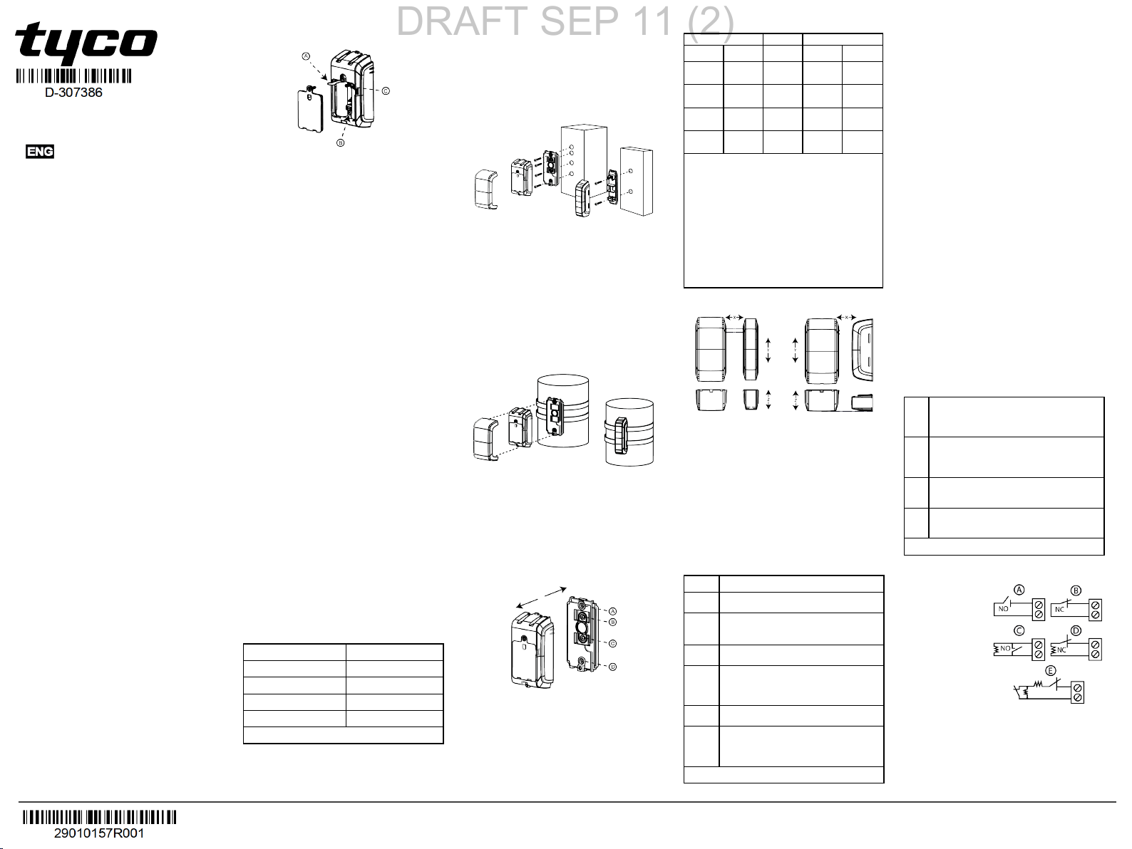
theenrollment button as seenin F igure 1 B.
A: Enrollmen t tab B: Enrollmen t bu tton
C: Tamp er switch
Figure 1 : Enrollment options
Installation
This equipment i s designedto be installed by qualified
service persons only. Place the device abovethe door
or window on the fixed frame and the magnet on the
movable part of the door or window. Do not place the
magnet more than44.5 mm (1.75 in) from the marked
side of the device.
To m onitor outdoor areas, you can m ount the PGx312
on a curved surface, such as a fencepole or si milar.
Note:
l Oncethe battery cover is removed, a tamper mes-
sage i s transmittedto the panel. Subsequent
removal of the battery prevents transmission of the
TAMPER R ESTORE alert, leaving the receiver in
permanent alert. To avoid this, press the tamper
switch w henyou remove the battery.
l It is recommended to wait about 1 minute after bat-
tery r emoval before insertingthe new batteries.
Caution! Risk of explosion if the battery is replacedby
an incorrect type. Dispose of theusedbattery according
to the manufacturer’s instructions.
Attention! Some m odels havea back tamper switch
behind the device. As longas the device is seatedfir mly
within the bracket, the switch lever will be pressed
against a special break-away bracket segment that is
loosely connected to thebracket. Be sure to fasten the
break-away segment to the wall. If the detector unit is
forcibly r emovedfrom thew all, this segment will break
away from the bracket, causing the tamper switch to
open.
Local diagnosticst est
A local diagnostic test establishes thesignal strength of
a device in its currentposition during the installation process. To perform this mandatory test, completethe following:
1. Separatethedecorative cover from thedevice and
unscrew the battery cover. See steps 1 to 3 of
Mounting the PGx312.
2. Press thetamper switch onceandr elease it.
3. Openthe door or window and verify thatdetection
is indicated by a r ed LED flash.
After two seconds, the LED flashes three times in
one of three colors to indicatethe si gnal strength.
LEDresponse Reception
Green LEDflas hes Strong
Yellow LED flas hes Good
Red LEDflas hes Poor
No fl ashes No c ommunication
Table 1: LEDreception response
Important! Reliable r eception must be assured. There-
fore, "poor" signal strength is not acceptable. If you
receive a "poor" signal from thedetector, relocateit and
re-test until a "good" or "strong" signal strength is
received( in regions requiring UL-compliant installation,
only “strong” signal strength is permitted).
Note:
l For UL, only strong signal strength is acceptable.
l For detailed diagnostics test instructions, refer to
thecontrol panel Installer Guide.
l After this step, r eattach the battery cover.
l The LED l ight is off in normal conditions.
Mount ing the PGx312
Figure 2 : Mounting on a fla t surfac e
1. Insert a flat-head screwdriver into the slot provided
and push upward to r emove the decorative cover.
2. Unscrew the lower screw from the device cover.
3. Separatethedevice from the bracket.
4. Mark and drill the requirednumber of holes in the
mounting surface.
5. Screw in the bracketwith four screws provided.
6. Reattach the device to the bracket.
7. Mount the magnet base with two supplied screws
to an adjacent surface and attach the magnet to the
magnet bracket.
Figure 3 : Mounting on a c urve d sur face with s traps
To m ount the device on a curved surface, use straps
(not included)as seen in Figure 3.
Note:
l Use holes A and D i n Figure 4 for standard m ount-
ing. Addholes B and C in Figure 4 for tamper protection.
l Align the device andmagnet accordingto the spe-
cifications in Range CoverageDirections.
A: Standa rd mo unting
C: Tamp er prote ction
Figure 4 : Dev ice and bra cke t s epar ation
B: Tamp er prote ction
D: Standa rd mo unting
Range coverage directions
Non-metallic surface Supports Metallic surface
Open Close Direction Open Close
71 mm
52 mm
(2.8 in.)
(2.0 in.)
40 mm
33 mm
(1.6 in.)
(1.3 in.)
22 mm
17 mm
(0.9 in.)
(0.7 in.)
85 mm
55 mm
(3.3 in.)
(2.2 in.)
Table 2 - Range coverage directions
Note:
l The values stated abovem ay vary by up to
10%.For steel installations, the gaps cannot be
less than 3.2 mm (0.1 in.).
l For roller shutter assembly, the magnet needs to
be mounted 25 mm to 35 mm ( 1.0 in. to 1.4 in.)
from the devices (on the X plane). For all other
installations, a m inimum gap of 5 mm (0.2 in.) i s
needed.
l When mounting on a slide door, refer to X. W hen
mounting on a roller shutter, refer to Y. W hen
mounting on a normal door, refer to Z.
Parallelm ag net Perpendicularm ag net
Figure 5 : Range cover age direc tions
Note:
l For UL commercial installations, the maximum
opening to activate i s 50.8m m (2 in.).
l Y ( up) r efers to theupper half of the Y plane. Y
(down) refers to thebottom half of the device on
theY plane.
l When mounting the magnet perpendicular to the
device, align themagnet with the face of the device
as seen in the perpendicular magnet im age.
Configuring the device parameters
Enter thecontrol panel D EVICE SETTINGS menu and
follow the configurationi nstructions for the PGx312 m agnetic contact device as describedin Table 3.
Option Configuration instructions
Magnetic
Determine whether to enable or dis able the
sensor
magnetic sens or.
Optional s ettings: Enable (default) or Dis-
X
Y (up)
Y(down)
Z
48 mm
(1.9 in.)
32 mm
(1.3 in.)
17 mm
(0.7 in.)
80 mm
(3.1 in.)
35 mm
(1.4 in.)
25 mm
(1.0 in.)
8 mm
(0.3 in.)
60 mm
(2.4 in.)
abled.
Define the external input acc ording to the
Input #1
installer's requirements.
Optional s ettings:Disabled (default), N O,
NC,EOL, or DEOL.
Note:DEOL s upport is dependent on panel
software versi on.
Anti-
Determine whether to enable or dis able the
mask
anti-masking.
Optional s ettings: D isabled (default) or
Enabled(default).
Note: This feature is dependent on panel soft-
ware version.
Table 3 - Magnetic device parameters
Wiring the auxiliary input
Note:
l For UL installations, the device connected to the i ni-
tiatingcircuit must be located in the same r oom as
thetr ansmitter.
l For UL installations, connect to U L listed res-
idential burglar alarm accessories only.
l For ULC installations, connect ULC listed products
only to theauxiliary wiring input.
l An alarm message transmits once the loop is
opened or short ci rcuited.
To connect this device wi th another nearby device by
auxiliary i nput, complete the following steps:
1. Remove the jacket at the endof the cable to
expose the wir es w ithin.
2. Perforate the sil icon gasketwith a 0.8 mm
(1/32i n.) pin.
3. Pass each wir e throughan entry hole and out the
oppositesi de.
4. Remove the insulationfrom theendof eachwire.
5. Connect each wir e to the relevantterminal, referencing Auxiliary Wi ring Options.
6. Screw the terminal closedusing a flat head screwdriver.
Note:
l Use a 22 AWG AUX cable (3.0mm, 0.12 in. j acket
diameter) for this installation.
l Use a cable shorter than 3 m (10 ft) for theAUX
connection.
l Seal the auxiliary wiri ng gasket w ith R TV Silicone
adhesive sealant.
Auxiliary wiring options
Youcan addm ore devices to the circuit of the PGx312
for NC, NO, EOL, or DEOL applications. Eachapplicationtype is as follows:
NC Excl usiv ely use series connected NC sensor con-
tacts i f the auxil iary i nput of the PGx312 i s
defined as a normally closed (NC)ty pe. An EOL
resistor is not required.
NO Exclus ivel y us e parallel c onnected NO sensor
contacts i f the auxi liary i nput of the PGx 312 is
defined as NO ty pe. An EOL resi stor is not
required.
EOL For EOL supervisi on, NCor NOsensor contacts
can be used. A 5.6k Ω EO L resistor must be wired
at the far end of the zone l oop.
DEOL For DEOL s upervision, onl y N.C. contacts should
be used. A 5.6kΩ EOL resistor must be wired at
the far end of the zone l oop.
Table 4:Auxiliary w iring options
Note:Figure 6 E illustrates a D EOL resistor setup that
is available dependent on panel software version.
A: N.O. switch
B: N.C. switch
C: EOL ; N .O. switch ;
use 5.6 kΩ resistor
D: EOL ; N .C. switch ;
use 5.6 kΩ resistor
E: DEOL ; N.C. swi tch
only ; use 5.6 kΩ
resistor
Figure 6 :Auxili ary wiring options
Calibrating the anti-mask
The anti-mask feature enables the detectionof attemptedsabotage, for example, sensor obstruction.
Note:
©2018 Tyco Security Products, Toronto, Canada www.dsc.com
Tech. Support: 1-800-387-3630
D-307386Rev.0 (09/18)
l This feature is dependenton panel software ver-
DRAFT SEP 11 (2)
sion.
l Begin the anti-mask calibrationprocess w henthe
device andm agnet are i n the final installation position. This must be the shortest distance between
them agnet and the device.
l For the proper operationof the AM function, align
them agnet with the sensor decorative cover during
calibration. See Figure 5 for parallel and perpendicular magnet i nstallation.
Pre-requisites:
l To r eceive an alert for m agnet interference, enable
theanti-masking configurationon the device settings menu.
l Completethe anti-masking learning process after
enrollment ( see Enrolling the PGx312) andwith the
device andm agnet in the final installationposition.
To enable the anti-mask feature, completethefollowing
steps:
1. Positionthedevice and magnet pointers to face
each other wi th referenceto RangeCoverage Dir-
ections.
2. Ensure thedeviceandm agnet are placed no more
than 5 mm apart on the Z plane. SeeR ange Cover-
age D irections.
Note: During the anti-mask learning process, the
sensor andthe m agnet must be stable for 10
seconds.
3. Press andhold the enroll button for 6-8 seconds to
start the anti-mask learning process.
Note: Do not r elease the enrollment button while
theyellow LED is l it. Releasethe button after the
green LED lights at 6 seconds andbefore 8
seconds.
If successful, the greenLED flashes three times. If
unsuccessful, the r ed LED flashes three times.
Note: If the door is open while the enroll buttoni s
pressed, the anti-mask l earning process is ignored.
Miscellaneous comments
DSC wir eless systems are very reliable and are tested
to high standards. However, due to low transmitting
power and limited range( requiredby FCC and other
regulatory authorities), there are some limitations to be
consideredas follows:
A. Receivers m ay be blocked by radio signals occurring on or near their operating frequencies, regardless of
thedigital codeused.
B. A receiver responds only to one transmitted signal at
a time.
C. Wir eless devices should be tested r egularly to
determine whether there are sources of interference and
to protectagainst faults.
Specifications
Frequency Band (MHz) :Europe and rest of world:
433-434, 868-869. USA:912-919
Maximum TxPower:
10dBm ( 10mW)@433MHz
14dBm ( 25mW) @868MHz
15dBm ( 30mW) @915MHz
Alarm input:One internal andoneauxiliary
Supervision:Signalling at 4-minute intervals
Tamper alert:Report whena tamper event occurs
Communication prot ocol:PowerG
Power supply: Tyce C
Battery type: 2 x 1.5 VAA Ul timate Lithium Energizer
battery only
Battery life expectancy: 5 years with typical commercial transmissions per day (not testedby UL)
Low battery t hreshold: 3.0 V
Battery supervision: Automatic transmission of bat-
tery conditiondata as part of the periodic status r eport
and i mmediately upon low battery detection.
Operating Temperature:-40 °C to 66 °C (-40°F to
151 °F)
Note:UL testingtemperatures: - 35 °C to 66 °C
(-31 °F to 151 °F)
Relative Humidity (R H): Average relative humidity of
approximately 75% non-condensing. For 30 days per
year relativehumidity may vary between 85% and 95%
noncondensing.
Note:For UL installations, relative humidity is 93%.
Dimensions ( LxWxD): 105m m x 52 mm x 35 mm
(4.1 in. x 2.0 in. x 1.4in.)
Device weight (including battery): 154 g ( 5.4 oz)
Color: Dark grey
UL/ULC n otes
TheP G9312 has been listedby UL for co mmercial and r esidentialburglar y applicationsand by ULC forr esidentialbur glary applications in acc ordanc e withthe
requirements inthe S tandardsUL 634 an d ULC/ORDC634 for Door and Window
Contact.For UL/ULC installationsus e thisd evice only in conjunction withc ompatibleDS C wireless receiv ers: HSM2HOST9, HS 2LCDRF(P )9,H S2ICNRF(P )
9,P G9920,WS 900-19, and WS900 -29.
Europe: CE /EN (E N50131-2- 6 GRADE 2, CLAS S IV,
EN50131- 6 Type C) listedP G8312:868 MHz PG4312: 433
MHz.Accor ding toE N 50131-1, this equipmentcan be applied in
installedsy stems up toan d including Sec urity Grade 2, Envir onmentalClass IV. UK :The P G8312 is suitable for use in sy stemsinstalled toc onformto PD6662 atGrade 2 and
environmentalclas s IV B S8243.
SIMPLIFIED EU DECLARATION OF CONFORMITY
Hereby, Tyco Safety Produc ts Canada Ltd declares thatthe radio equipmenttype
is in compliance withD irective 2014/53/E U.The full textof theE U declar ationof
conformity is av ailablea tthe followinginternetaddr ess: www .dsc.com
PG4312: http://dsc.com/pdf/1808001
PG8312: http://dsc.com/pdf/1808002
Frequency Bands Maximum Power
868.0MHz - 868.6 MHz 14dBm (25mW)
868.7MHz - 869.2MHz 14dBm (25mW)
433.22MHz - 434.64MHz 10dBm (10mW)
European single pointof contact:Tyc o Safety Pr oducts, Voltaweg 20,6101 XK
Echt,N etherlands.
FCC C OMPLIANCE STATEMENT
WARNING!Changes or modifications to thisunit note xpres sly appr oved by the
party respo nsible for compliance could vo idthe us er’s authority tooper atethe
equipment.
This device has been tested and found toc omplyw iththe limits for a Class B digital
device, pursua ntto Par t15 of the FCC Rules. These limits are d esigned to provide
reasonable pr otectionagainst harmfulinterference in res identialinstallations. This
equipmentgenerates use s and c an radiate radio frequency energy an d,if not
installedand us ed in acc ordance w iththe instructions,may c ause har mfulinterference tor adio and television rec eption.
However ,there is no guarantee thatinterference willnot occ ur in a par ticular installation.Ifthisdev ice does cause such interference,which c an be v erifiedby turning
thedev ice offand on, the user is encouraged toeliminatethe interference by one
or more ofthe followingmeasur es:
– Re-orient or re -locate ther eceiving antenna.
– Increase the distance between the devic e and the receiver .
– Connect the device to an outleton a c ircuit different fromthe one thatsupplies
power to ther eceiver .
– Consult thedealer or an ex perienced r adio/TVtechnician.
FCC ID:F5318PG9312
Innovation Scienc e and Economic Dev elopment Ca nada
(ISED) Statement
This equipmentcomplies withFCC a nd ISED C anada RF radiation exposur e limits
set forthfor an uncontrolled enviro nment.
This device c ompliesw ithFCC Rules Part 15 and w ithISED Canada licenc eexemptRSS standard(s ). Operationis subject tothe followingtwo c onditions:
(1) This dev ice may not cause harmfulinterference,and ( 2) this devic e must
accept any interferencethat may be receiv ed or thatmay c ause undes ired operation.
Le present appareil es tc onformeaux CNR d'ISE D Canada app licables aux
appareils radio ex emptsde licenc e.L 'exploitation est autorisee aux deu x conditionss uivantes :(1) l'appareil ne doit pas produire de brouillage,et (2) l'utilisateur
de l'appareil doitacc epter toutbrouillage radioelectrique sub i,memesi le br ouillage est susc eptibled'en c ompromettre lefonctionnement.
W arrant y
(a) NO WA RRA NTY - D SC P ROVIDES THE SOFTWARE “AS IS” WITHOUT
WARRA NTY. DSC DOES NOT WARRA NT THAT THE SOFTWAREWILL
MEET YOUR REQUIREMEN TS OR THAT OP ERA TIONOF THE
SOFTWAREWILL B E UNINTER RUPTE D OR ER ROR-FREE .
(b) CHA NGES IN OPE RATING ENV IRONMENT- DSC shall notb e respons ible
forpr oblems caused by cha nges in the operating charac teristics ofthe
HARD WARE ,or forpr oblems in theinteraction ofthe SOFTWARE PR ODUCT
withnon-D SC- SOFTWARE or HA RDWAR E P RODUCTS.
(c) L IMITATION OFL IABILITY;WARR ANTY REFLEC TS ALL OCATIONOF
RISK - INA NY EV ENT, IFANY S TATUTE IMPLIES WA RRAN TIES OR
CONDITIONS NOT S TATED IN THIS LICENS E A GREE MENT,D SC’S ENTIRE
LIABILITYU NDER ANY PROV ISIONOF THIS LICENS E A GREE MENT
SHA LL BE LIMITED TO THE GRE ATER OFTHE AMOUNT ACTUA LLY PA ID
BY YOU TO LICENS E THE SOFTWARE PRODU CT AND FIVE CAN ADIAN
DOLLARS (CA D$5.00).B EC AUS E S OME JURISD ICTIONS DO NOT A LLOW
THE E XCLUS IONOR LIMITATION OF LIABILITYFOR CONS EQUE NTIAL OR
INCIDENTAL DA MAGES, THE AB OVE L IMITATION MAY N OTA PP LY TO
YOU.
(d) DISCLA IMER OFWA RRA NTIES - THISWA RRA NTY CONTA INS THE
ENTIRE WA RRAN TY AN D SH ALL B E IN LIEU OF AN Y A ND A LL OTHER
WARRA NTIES, WHETHE R E XP RES SE D OR IMPLIED (INCLUDING ALL
IMPLIED WA RRA NTIES OF MERCHA NTAB ILITY OR FITNESS FOR A
PA RTICULAR P URPOS E) AND OF A LL OTHER OB LIGATIONS OR
LIABILITIES ON THE P ART OF DSC .DS C MAK ES NO OTHER
WARRA NTIES. DSC NEITHER A SS UMES NOR AU THORIZES ANY OTHER
PE RSON P URP ORTINGTO ACT ON ITS BE HA LF TOMODIFY OR TO
CHAN GE THIS WAR RANTY ,NOR TO A SS UME FOR ITA NY OTHE R
WARRA NTY OR LIAB ILITYCONC ERNING THIS SOFTWARE PR ODUCT.
(e) E XCLU SIVE REMEDY AN D LIMITATIONOF WARR ANTY - UNDE R NO
CIRCUMSTANCE S S HAL L DSC BE LIABLE FOR ANY SP ECIAL,
INCIDENTAL,C ONSE QUENTIAL OR INDIRECT DA MAGES BA SE D UP ON
BRE ACH OFWA RRA NTY, BRE ACH OFCONTRA CT,NE GLIGENCE,
STRICTLIAB ILITY,OR ANY OTHER LEGAL THEORY. SU CH DA MAGES
INCLUDE, BUT A RE NOTLIMITEDTO,L OSS OF P ROFITS, LOSS OFTHE
SOFTWARE PRODUC TOR A NY AS SOCIATED EQUIPMENT, COST OF
CAP ITAL,COST OF SU BS TITUTE OR RE PLA CE MENT EQUIPMENT,
FACILITIES OR S ER VICES ,DOWN TIME,P URCH AS ERS TIME,THE
CLAIMS OFTHIRD P ARTIES ,INCLUDING CUS TOMERS, AND INJURY TO
PROP ERTY. WAR NING:
DSC r ecommends thatthe entires ystem be completelytested on a regu lar basis.
However ,des pitefrequent testing,and due to,but notlimitedto,cr iminaltampering
or electrical disrup tion,itis pos sible for thisS OFTWARE P RODUCT to failto performas ex pected.The term ICbe forethe radio c ertification number signifiesthat the
Industry Canada technical s pecificationsw ere met.This Class B digitalappara tus
complies withCanadian ICE S-003. This dev ice complies with RSS -247 of
Industry Canada. Operationis subject tothe followingtwo co nditions:(1) this
device may not caus e interference,and (2) this devic e mustac cept any interference,inc ludinginterference that may cause u ndesired oper ationof thedev ice.
Cetappar eilnu mériquede lac lasse B es tco nformeà la norme NMB- 003 du
Canada.C e dispositifsatisfaitaux exigences d’IndustrieCanad a,pres crites dans
ledo cumentCNR -247. son utilisationest autorisée seu lementaux con ditions
suivantes: (1) il ne doit pas prod uire de brouillage et (2) l’utilisateurdu dispos itifdoit
êtrepr êtà a ccepter toutbr ouillager adioélectriquer eçu, mêmesi c e brouillage est
susc eptiblede c ompromettrele fonctionnementdu dispos itif.
©2018 Tyco Security Products, Toronto, Canada www.dsc.com
Tech. Support: 1-800-387-3630
D-307386Rev.0 (09/18)
 Loading...