

Tyco Safety Canada 18PG9307 Users manual

D-307315
A
B
B
C
D
E
4 Selec t the desire d z one number.
B
A
C
A
B
3/4 in (
19.05 mm)
2.68 in
(68 mm)
0.6 in
(15 mm)
0.08 in
2 mm
Device/Frame
Magnet/Door
7/8 in (
22.2 mm)
5 Configure any devic e pa ra mete rs that are
require d.
6 Mount a nd te st the device . See Placement
Testing for information on testing the
devic e. In addition, see the alarm systems
Installation Manual tha t the device is
enrolled on for other te st proc edures that
PG9307 PowerG recessed door/window contact
The PG9307 is a discre et, supervise d, 2- way wireless
PowerG magnetic contac t devic e.
The PG9307 uses a repla ceable lithium battery a nd
should la st 10 year s under normal usage.
Legend
Rec essed door/window contact
A Door / window contact housing
B Bre akable sc re w e ar s
C Contact cove r and c irc uit boar d
D Magne t cove r
E Magnet with double- sided ta pe
Inserting or replacing the batt ery
CAUTION! This produc t uses lithium ba tter ies.
Improper handling of lithium batteries may result in
HEAT GENERATION, EXPLOSION or FIRE, which
may lead to personal injuries.
WARNING! Danger of explosion if batterie s are
installed incorrec tly. Replace only with the same or
equiva lent type rec ommended by the manuf ac ture r.
Dispose of used batterie s acc ording to the manufactur er 's instr uctions a nd a ccording to loc al r ules
and regulations.
Kee p away fr om sma ll children: if swallowe d
promptly se e a doctor.
Do not try to re charge these batteries.
NOTE: Battery replacement should be done by an
installer .
1. Insert a small, flat-hea d screwdriver into the slots
on the side of the contact housing a nd relea se the
contac t cover.
2. Pull out the c over fr om the door/window contact
housing.
3. Observe the polarity a nd insert or replac e the battery.
4. Reinsert the contact cover (with c ircuit board
attached).
Enrollment
Refe r to the panel installation manual for the enr ollment proce dure.
A general description of the pr ocedur e is provided in
the following flow chart:
Step Proc edure
1 See the Installation Manual for the ala rm sys-
tem that the device is being e nrolled on to
ensur e that the proper steps are used.
2 Enter the de vice enrollment option through
the specif ied method a nd selec t the appropriate option toadd the ne w devic e.
3 Insert the battery and wait for the panel to
dete ct the devic e or enter the de vice ID.
PG9307 PowerG recessed door/window contact Installa tion Instructions ©2017 Tyco Security Products, Toronto, Canada ww w.dsc. com Tech. Support: 1-800-387-3630 1
Figure 1.
are required.
Performing a placement t est
Befor e you per mane ntly mount any wireless device,
temporarily mountthe devic e and perform a plac ement test on the door frame, as close as possible to the
planne d insta llation a re a. This is f or che cking the
radio link.
1. To tamper the device, pull the cove r attached to
the device.
2. Reinsert the cover to restore the tamper. The
device now enters placement test mode for 15
minutes.
3. Trip the device by opening the door or window
and verify that the red LED blinks, indicating
detec tion.
Afte r 2 se conds the LED blinks 3 times. The following
table indicates the r ec eived signal stre ngth.
LED R esponse Signal Strength
Green LED blinks STRONG
Orange LED blinks GOOD
Red LED blinks POOR
No blinks No communication
IMPORTANT! Only GOOD or STRONG signal
strengths are ac cepta ble. If you r ec eive a POOR signal from the device, re-loca te it and re- test until a
GOOD or STRONG signal is re ceive d.
NOTE: For UL/ULC installations, only STRONG signal levels are ac ceptable. Afte r insta llation verif y the
produc t f unctionality in conjunction with the compatible control pa nels HSM2HOST9, HS2LCDRF(P)9,
HS2ICNRF(P)9, PG9920, WS900-19, a nd WS900- 29.
NOTE: For detailed Plac eme nt instructions refer to
the control pa nel refer enc e manua l.
Installation t ips
WARNING:To comply with FCCa nd I SED Canada
RF exposure compliance require ments, the contac t
should be loca ted at a distance of at least 20 cm from
all persons during normal ope ra tion. The antenna s
used for this produc t must not be co-loca ted or ope rated in conjunc tion w ith a ny other a ntenna or transmitter.
NOTE:The PG9307 PowerG re ce ssed door/window
conta ct shall be installed and used within an environment that provide s the pollution de gree max 2 and
over voltage s cate gory II in NON H AZA RDOUS
LOCATI ONS. The equipment is de signed to be
installed only by qua lifie d servic e pe rsons.
It is re commende d to install the contac t in the door
fra me and the magnet in the door.
NOTE:Before drilling holes, test the location. Te mpora rily mount the contac t and ma gne t a nd pe rform a
plac eme nt test.
Once drilled, the signal quality may be impa cte d.
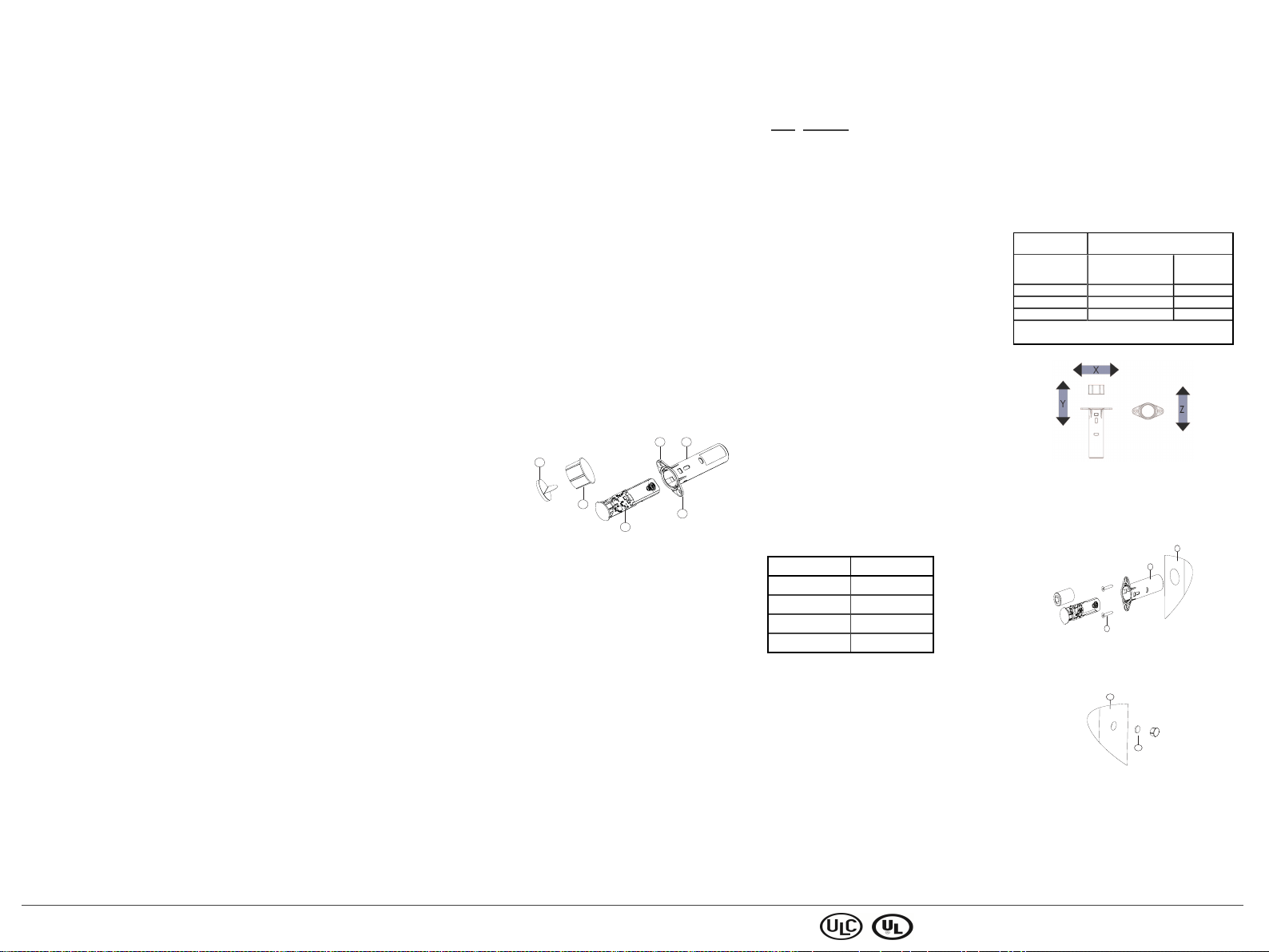
Gap separation
The following table outlines the gap separation information.
Direction of m ov ement
of the mag net
Axis X 15 mm 17 mm
Nonm etallic wood/plastic materials
Approach/Make Remove/
Break
Axis Y 15 mm 17 mm
Axis Z 2 3 mm 28 mm
The recommended maximum gap separa tion for
installation (on specif ied mate ria ls and Axis Z) is 6
mm (0.24 in.).
Figure 2.
Mount ing the device
NOTE: Ther e a re various wa ys to mount the device.
This proc edure outlines one option for installation.
Allow 3mm minimum betwee n the door a nd fra me.
Figure 3: Mounting the rec esse d door/window c ontact
A Door frame
B Rec essed door/window contact
C Scre ws
Figure 4: Mounting the magnet
A Door
B Magnet
Install the device in the door frame , a nd insta ll the
magne t on the door. Install the device and magnet on
either the side or the top of the door and the door
fra me.
Mark the locations for the door/window conta ct and
the magnet. Ensure that the locations for the contac t
and the magnet are cor re ctly aligned.
Sens or i nstallation.
Install the se nsor by the following steps:
1. Use a 3/4 drill bit to slowly drill a 3/4 inch hole for
the door/window contact in the door fra me.
2. Fasten the c ontact housing to the mounting surface
with the two screws and insert the cover. If there
is no 3mm ga p available betwe en the door and the
fra me, two step drilling is necessary. Using a
22mm tool, drill a 2mm shallow, followed by a
70mm deep hole with a 19mm tool. Brea k the slot
ears, clean the sharp edges and insert the device.
The device is recessed inside the frame, not interfer ing with the door.
Figure 5.
Magnet installation.
Install the ma gnet by either of the following options:
1. By drilling:
2. By using the double-sided tape without the magnet
NOTE: Option 2 is possible only when there is a minimum gap of 2 mm betwee n the door a nd the door
fra me.
Optional: Use a stic ker on both the contac t cove r a nd
the magnet c over to match the color of the door or the
door fra me.
Specifications
Fre quency 912 MHz to 919 MHz
Comm unication
protoc ol
Maximum
power
Batte ry type Panasonic or GP, 3V CR-2 or equi-
Batte ry life
expec tancy
Batte ry
supervision
Low battery
trouble leve l
Temperat ure
range
Relat ive
humidity
Magnet type Rare ea rth
Contac t size
(HxD)
Magnet cover
size (HxD)
Weight (with
batte ry and
magnet )
Color White or c lea r
Housing
mater ial
Figure 6: Sensor installation
a. Use a 3/4 inch dr ill bit to crea te a 15mm deep
hole.
b. Peel off the double-sided tape on the magne t
and stick it inside the magne t cover (part D).
housing:
a. Peel of f the double-sided tape on the magne t
and stick it on the door/window.
PowerG
+14 dBm
vale nt lithiumbattery
10 years (with typical use)
Automatic transmission of battery
condition data as par t of pe riodic
status re port and immediately upon
low battery c ondition detection.
2.5 V
-10 °C to 50 °C
5% to 95% non c onde nsing
2.66 inches x 0.75 inches
0.67 inches x 0.08 inches
0.83 oz (25 g)
Polycar bona te
Figure 7.
Compatible receivers
This devic e c an be used with DSC panels and receivers tha t use Power G tec hnology.
UL /U L C N ot es
Only mod el PG930 7 operating in the frequency b and 9 12 919 MHz is UL/ULC listed . The PG9 307 has been lis ted by
UL for co mmercial and residential burglary applications and
by ULC for residential burglary applicatio ns in accordance
with the requirements in th e Stan dards UL 634 and ULC
ORD-C63 4for Intrusio n Detection Units.
For UL/ULC installatio ns use these device on ly in con junction with comp atible DSC wireless receivers:
HSM2HOST9, HS2LCDRF(P)9, HS2ICNRF(P)9, PG992 0,
WS90 0-19, and WS900-29. After installation verify the
product fun ction ality in conjunction with the com patib le
receiverus ed.
FC C COM PL IA N CE STA T EM EN T
WARNING!Chan ges or m od ifications to this u nit not
expressly ap prov ed b y the party respons ible for com plian ce
could vo id th e u ser’s autho rity to operate the equ ipm ent.
This device has been tested and foun d to comply with the
limits for a Class B digital device, pursu ant to Part 15 of
the FCC Rules. These lim its are designed to prov ide reasonab le p rotection again st harmful interference in residential
installatio ns. This equipment gen erates u ses and can radiate
radio frequency energy and, if not installed and used in
accordance with th e instructions, may cause harmful interference to radio and televis ion reception .
However, there is no g uarantee that interference will no t
occur in a p articular in stallatio n. If this device does cause
such interference, which can be verified by turning the
device off an d on, the user is encouraged to eliminate the
interference by one or more o f the following measures:
– Re-orient or re-locate the receiving antenna.
– Increase the d istan ce between the d evice and the receiver.
– Conn ect the device to an outlet on a circuit different from
the one that supplies po wer to th e receiver.
– Cons ult the d ealer or an experienced radio/TV technician.
FCC ID: F5 31 8PG9307
Innovation Science and Economic Development
Canada (ISED) Statement
This equipm ent comp lies with FCC and ISED Can ada R F
radiation exp osu re limits set forth for an uncontrolled env ironm ent.
This device complies with FC C Ru les Part 15 and with
ISEDCanada licence-exemp t RSS stand ard(s). Operation is
sub ject to the follo wing two cond itions: (1)This dev ice
may not cause harmful interference, and (2) this d evice
mus t accept any interference that may be received or that
may cause und esired operation .
Le present appareil est con forme aux CNR d'ISEDC anada
applicables aux appareils radio ex empts d e licence. L'exploitation est autorisee aux deux co ndition s suiv antes :(1)
l'appareil ne d oit pas produire d e brouillage, et (2) l'utilisateur de l'appareil doit accepter tout b rouillage radioelectrique sub i, meme si le brou illage est su sceptib le d'en
comp romettre le fonctio nn ement.
IC: 1 60 A-PG930 7
Limited Warrant y
Digital Security Controls (DSC) warrants that for a period of
twelve months from the date of purchase, the produ ct shall
be free of defectsin materials and workmansh ip und er normal use an d th at in fulfilment of an y breach of su ch warranty, DSC shall, at its o ptio n, repair or replace the
defective equipm ent up on return of the equ ipm ent to its
factory. This warranty app lies on ly to defects in parts an d
workman ship and not to damage incurred in ship pin g or
hand ling , or damage due to causes b eyon d th e co ntrol o f
DSC s uch as ligh tnin g, excessive voltage, mechanical
sho ck, water dam age, or damage arising out o f ab use, alteration or im prop er application of th e equipment.
The forego ing warranty shall apply o nly to the original
buy er, and is and shall be in lieu of any and all other warranties, whether expressed or implied and of all other obligations or liabilities on the p art of DSC. This warranty
contain s th e entire warranty. Digital Security Co ntrols
A
B
B
C
D
E
B
A
C
A
B
neither ass umes responsibility for, nor auth orizes any other
person purpo rting to act on its b ehalf to modify o r to
chang e this warranty, nor to assume for it any o ther warranty or liability concernin g this product. In no ev ent shall
DSC b e liable for any directo r indirect o r co nseq uential
damages, lo ss o f an ticipated profits, lo ss o f time or any
other loss es incurred by the buyer in co nn ection with th e
purchase, installation or operation or failure o f this produ ct.
Warning : Digital Security Controls recommend s that the
entire sy stem be co mpletely tested on a regular b asis.
However, despite frequent testing, and du e to, but not limited to, criminal tamp ering or electrical d isrup tion , it is po ssible for this product to fail to perform as expected.
IMPORTANT - READ CAREFULLY: DSC Software purchased with or with ou t Produ cts and Comp on ents is co py righted and is purchased und er the following license terms:
This End-User License Agreement (“EULA”) is a leg al agreement between You (the compan y, individual or entity who
acquired the Software and an y related Hardware)and Dig ital
Security Co ntrols, a div isio n of Tyco Safety Products
Canada Ltd. (“DSC”), the manufacturer of th e integrated
security systems and the d eveloper of the software an d any
related prod ucts or co mponen ts (“HARDWARE”) which
You acquired. If the DSC software p roduct (“SOFTWARE
PRODUCT”or “SOFTWARE”) is intended to be accom panied by HARDWARE, and is NOT accompan ied by new
HARDWARE, You may not use, co py or ins tall the
SOFTWAREPRODUCT. The SOFTWARE PRODUCT
includ es co mputer software, and may include asso ciated
media, printed materials, and “online” o r electronic documen tation . Any software provided along with th e
SOFTWAREPRODUCT that is associated with a separate
end-user license agreement is licens ed to You under the
terms o f that license agreement.
By installin g, cop yin g, do wnlo ading, storing , accessing o r
otherwise u sing the SOFTWAREPRODUCT, You agree
unco nd ition ally to be bou nd by the terms o f this EULA,
even if this EULAis deemed to b e a mod ification of any
previou s arrangement or con tract. IfYou do not agree to the
terms o f this EULA, DSC is un willing to license the
SOFTWAREPRODUCT to You , and You have no righ t to
use it.
SOFTWARE PR ODUCT LICENSE
The SOFTWARE PRODUCT is protected by cop yrigh t laws
and internation al copyrigh t treaties, as wellas other intellectual p roperty laws and treaties. The SOFTWARE
PRODUCTis licensed, no t sold.
1. GRANTOF LICENSE This EULA g rants You the following rights:
(a)Software Installation and Use- Fo r each license You
acquire, You may have only one cop y of th e SOFTWARE
PRODUCTin stalled.
(b) Sto rage/Network Use - The SOFTWAREPRODUCT may
not be installed, accessed, dis played, run, s hared or used
concu rrently on or from d ifferent comp uters, including a
workstatio n, terminal or other digital electronic device
(“Device”). In other words, if You have several workstation s, You will h ave to acquire a license for each workstation where the SOFTWARE will be u sed.
(c)B ackup Copy - You may make back-up copies o f the
SOFTWAREPRODUCT, but You m ay o nly have one copy
per license installed at any given tim e. You may use th e
back-up copy solely for archiv al purpo ses. Except as
expressly p rovid ed in this EULA, You may not otherwise
make copies of the SOFTWARE PRODUCT, in clud ing th e
printed materials accomp anying the SOFTWARE.
2. DESCRIPTION OF OTHER RIGHTS AND LIMITATIONS
(a)Limitation s on Reverse Engineering, Decomp ilation and
Disassemb ly - You may no t reverse engineer, d ecomp ile, or
disass emble th e SOFTWARE PRODUCT, except and only
to the ex tent that su ch activity is expressly permitted by
applicable lawn otwith standing this limitation. You may
not make any chan ges or modifications to th e So ftware,
withou t th e written permission of an o fficer of DSC. You
may not remove any prop rietary no tices, marks or labels
from the Software Produ ct. You shall in stitu te reasonable
measures to ensure compliance with the terms and con ditio ns of this EULA.
(b) Separation o f Co mp on ents - The SOFTWARE
PRODUCTis licensed as a sin gle prod uct. Its compo nen t
parts m ay n ot be separated for u se on more than one
HARDWAREu nit.
(c)Single INTEGRATED PRODUCT - If You acquired this
SOFTWAREwith HARDWARE, then the SOFTWARE
PRODUCTis licensed with the HARDWARE as a single
integrated prod uct. In this case, the SOFTWARE PRODUCT
may only be u sed with the HARDWARE as set forth in th is
EULA.
(d) Ren tal - You may not rent, lease or lend the
SOFTWAREPRODUCT. You m ay not m ake it available to
others or post it o n a server or web site.
(e)Software Prod uct Transfer - You may transferall o f Your
rights und er this EULA only as part o f a p ermanent sale or
transfero f the HARDWARE, provid ed You retain no copies, You transfer all of the SOFTWARE PRODUCT (including all co mp onent parts, the media and printed m aterials,
any upg rades and this EULA), an d p rovid ed the recipient
agrees to the terms o f th is EULA. Ifthe SOFTWARE
PRODUCTis an upgrade, any transfer m ust also includ e all
prior v ersion s of the SOFTWARE PRODUCT.
(f)Terminatio n - Withou t prejud ice to an y o ther rights,
DSC m ay terminate this EULAif You fail to comply with
the terms and con ditio ns of th is EULA. In su ch event, You
mus t destroy all co pies o f th e SOFTWARE PR ODUCTand
all o f its com ponent parts.
(g) Trademarks - This EULAd oes n ot grant You any rights
in connectio n with any trademarks or service marks of DSC
or its su pp liers.
3. COPYRIGHT - All title and intellectual p roperty rights in
and to the SOFTWARE PRODUCT(inclu din g but not limited to an y im ages, p ho tog raphs, and text in corporated in to
the SOFTWARE PRODUCT), the accomp any ing printed
materials, and any copies of the SOFTWARE PRODUCT,
are owned by DSC or its sup pliers. You m ay n ot copy the
printed materials accomp anying the SOFTWARE
PRODUCT.All title an d in tellectual property rights in and
to the co ntent which may be accessed through use o f the
SOFTWAREPRODUCT are the property of the respective
conten t o wner and may be protected by applicable copyright or other intellectual property laws and treaties. This
EULA grants You no rights to us e such content. All rights
not expressly g ranted un der th is EULA are reserved by DSC
and its suppliers.
4. EXPORT RESTRICTIONS - You agree that You will n ot
expo rt or re-export the SOFTWARE PRODUCT to any
coun try, person, or entity subject to Canadian export restriction s.
5. CHOICE OF LAW - This Software License Agreement is
gov erned b y the laws of th e Prov ince of Ontario, Canada.
6. ARBITRATION - All dis pu tes arising in conn ection with
this Agreement shall be determined by final and bin din g
arbitration in accordance with the Arbitration Act, and the
parties agree to be bo un d by the arbitrator’s d ecision . The
place o f arbitration shall be Toronto , C anada, and the languag e o f th e arbitration shall b e English.
7. LIMITED WARRANTY
(a)NO WARRANTY - DSC PROVIDES THE SOFTWARE
“AS IS” WITHOUT WARR ANTY. DSC DOES NOT
WARRANTTHAT THE SOFTWARE WILL MEETYOUR
REQUIREMENTS OR THAT OPERATION OF THE
SOFTWAREWILL BE UNINTERRUPTED OR ERRORFREE.
(b) CHANGES IN OPERATING ENVIRONMENT - DSC
shall not b e resp on sible for problems caused by chan ges in
the operating characteristics of th e HARDWARE, or for
problems in th e interaction of the SOFTWARE PRODUCT
with non-DSC-SOFTWARE o r HARDWARE PRODUCTS.
(c)LIMITATION OF LIABILITY; WARRANTY REFLECTS
ALLOCATION OF RISK - IN ANY EVENT, IF ANY
STATUTEIMPLIES WARRANTIES OR CONDITIONS NOT
STATEDIN THIS LICENSE AGREEMENT, DSC’S ENTIRE
LIABILITY UNDER ANY PROVISION OF THIS LICENSE
AGREEMENT SHALL BE LIMITED TO THEGREATER OF
THEAM OUNT ACTUALLY PAID BY YOU TO LICENSE
THESOFTWARE PRODUCT AND FIVE CANADIAN
DOLLARS (CAD$5.0 0). BECAUSESOME
JURISDICTIONS DO NOT ALLOW THE EXCLUSION OR
LIMITATION OF LIABILITY FOR CONSEQUENTIAL OR
INCIDENTAL DAMAGES, THEABOVE LIMITATION
MAY NOT APPLY TOYOU.
(d) DISCLAIMER OF WARRANTIES - THIS WARR ANTY
CONTAINSTHE ENTIRE W ARRANTYAND SHALLBE IN
LIEU OF ANY AND ALL OTHER W ARRANTIES,
WHETHER EXPRESSED OR IMPLIED(INCLUDING ALL
IMPLIEDWARRANTIES OF MERCHANTABILITYOR
FITNESS FOR A PARTICULAR PURPOSE) AND OF ALL
OTHER OBLIGATIONS OR LIABILITIES ON THE PART
OF DSC. DSC MAKES NO OTHER WARRANTIES. DSC
NEITHER ASSUMES NOR AUTHORIZES ANY OTHER
PERSONPURPORTINGTO ACT ON ITS BEHALFTO
MODIFY OR TO CHANGE THIS WARRANTY, NOR TO
ASSUME FOR IT ANY OTHER WARRANTY OR
LIABILITY CONCERNING THIS SOFTWARE PRODUCT.
(e)EXCLUSIVE REMEDY ANDLIMITATION OF
WARRANTY- UNDER NO CIRCUM STANCESSHALL
DSC B E LIABLE FOR ANY SPECIAL, INCIDENTAL,
CONSEQUENTIALOR INDIRECT DAMAGES BASED
UPON BREACH OF WARRANTY, BREACH OF
CONTRACT, NEGLIGENCE, STRICT LIABILITY, OR ANY
OTHER LEGAL THEORY. SUCH DAMAGES INCLUDE,
BUT ARE NOT LIMITED TO, LOSS OF PROFITS, LOSS
OF THE SOFTWARE PRODUCT OR ANY ASSOCIATED
EQUIPMENT, C OST OF CAPITAL, COST OF
SUBSTITUTE OR REPLACEMENTEQUIPMENT,
FACILITIES OR SERVICES, DOWN TIME, PURCHASERS
TIME, THE CLAIMS OF THIRDPARTIES, INCLUDING
CUSTOMERS, ANDINJURY TO PROPERTY. WARNING:
DSC recom mend s that the entire system be comp letely
tested on a regular basis. However, despite frequent testing,
and due to, b ut not limited to, criminal tampering or electricaldisrup tion, it is pos sible forthis SOFTWARE
PRODUCTto fail to perform as expected.
The term IC before the radio certification numb er signifies
that the Ind ustry Canada technical specification s were met.
This Class B digital apparatus complies with Canadian
ICES-003. This device comp lies with RSS-247 of Ind ustry
Canada. Operation is subject to the following two co nditio ns: (1) this device may not cause interference, and (2)
this device mu st accept any interference, in cluding interference that may cause und esired operation o f th e dev ice.
Cet appareil n um érique de la classe B est conforme à la
norme NMB -00 3 du Canada. Ce disp ositif s atisfait aux exigences d’Industrie Canada, prescrites dans le docu ment
CNR-247. son utilisatio n est au torisée seulemen t aux conditio ns suivan tes: (1) il n e d oit pas p rodu ire de brouillage
et (2) l’utilisateur du dispo sitif doit être p rêt à accepter tout
brouillage radioélectrique reçu, même si cebrouillage est
susceptible de comprom ettre le fon ction nemen t du dispos itif.
Contact encastré pour porte/fenêtre PowerG PG9307
Le PG9307 est un é mette ur à contac t magnétique bidirec tionne l PowerG sans fil, discre t et gé ré .
Le PG9307 utilise une pile lithium remplaçable offrant
10 année s d'autonomie en conditions normales d'utilisation.
Légende
Contac t encastr é pour port e/f enêtre
A Boîtier du contact pour porte/fe nêtre
B Aile ttes de visca ssables
C Capot du contact et carte à cir cuit imprimée
D Capot de l'aimant
E Aimant avec ba nde adhé sive double- fa ce
Insertion ou remplacement de la pile
ATTENTION:Ce produit utilise des piles a u lithium.
Toute manipulation incor re cte des piles au lithium
peut entra îner une ÉMISSION DE CHALEUR, une
EXPLOSIO N ou un INCENDIE pouva nt entraîne r des
blessures.
ATTENTION:Mal positionné es, le s piles pour ra ient
explose r. Rempla ce z les pile s uniquement ave c des
piles du modèle conseillé pa r le fa bricant, ou pa r un
modèle équiva lent. Mettez les piles usagée s au rebut
en suivant les instructions du fa bricant et c onformément aux règles et réglementations locales.
Tene z-les hor s de portée des e nfants: en cas d'ingestion, c onsultez immédiatement un médec in.
N'essayez pas de rec har ger ce s piles.
REMARQUE:Le r emplacement de la pile doit être
effectué par un installateur .
1. Insérez un petit tourne vis plat dans les fentes
latéra les du boîtier du contact et libérez le capot.
2. Retirez le capot du boîtier du contact pour fenêtre /porte.
3. Respectez la polarité et insérez ou remplacez la
pile.
Figure 1.
4. Remettez en place le ca pot du c ontact (ave c ca rte
à circuit imprimée fixée).
Enregistrement
Pour des inf orma tions détaillée s sur la proc édure d'enregistrement, consultez le manuel d'installation de la
ce ntra le.
Une desc ription géné rale de la procé dure est indiquée
dans le tableau suivant:
Étape Proc édure
1 Consultez le manue l d'installation du systè me
d'alar me dans leque l l'appareil e st enre gistré
afin de suivr e la proc édure a déquate.
2 Utilisez la méthode préc onisée pour acc éder
à l'option d'enre gistre ment de l'appa re il et
sélectionne z l'option correspondante pour
ajouter un nouvel appar eil.
3 Insére z la pile et attendez que la c entrale
déte cte l'appar eil, ou saisissez l'identifia nt de
l'appar eil.
4 Sélec tionnez le Numéro de zone voulu.
5 Configurez les paramètres néce ssair es de
l'appar eil.
6 Montez et te stez l'appar eil. Pour savoir com-
ment tester l'appa reil, consultez la section
Test d'emplacement. Consultez é galement le
Manue l d'installation des systè mes d'ala rme
dans lesquels l'appa re il est e nregistré pour
conna ître la procé dure à suivre.
Test de l'emplacement
Avant d'installe r un appar eil sans fil de ma nièr e dé finitive, montez l'appar eil provisoireme nt et testez sa position sur le dormant, le plus près possible de
l'emplaceme nt prévu. Cec i permet de tester la liaison
radio.
1. Pour déclencher l'auto-protec tion de l'appareil,
retire z le capot fixé à l'appareil.
2. Réinsérez ensuite le capot pour rétablir l'auto-protection. L'appareil pa sse en mode de test d'emplace ment pendant 15 minutes.
3. Déc lenchez l'appareil en ouvrant momentanément
la porte ou la fe nêtre e t vérifiez que le voyant
rouge clignote pour signaler la détection.
Au bout de 2 se condes, le voyant clignote 3 fois. Le
tableau ci-dessous indique la puissanc e du signal reçu.
Voyant Puissa nce du signal
Voyant vert clignotant F ORT
Voyant orange clignotant BON
Voyant rouge clignotant FAIBLE
Aucun clignotement Pas de comm.
IMPORTANT! Seul un signal BON ou FORT est
ac ce ptable. Si vous rec evez un signal FAIBLE de l'appareil, change z-le d'emplace ment e t recommenc ez le s
tests jusqu'à obtenir un signal BON ou FORT.
REMARQUE:Pour les installations c onformes
UL/ULC, seul un signal FORT est a cce ptable. Aprè s
l'installation, vérifie z le fonc tionnement du produit
ave c les centrales HSM2HOST9, H S2LCDRF(P)9,
HS2ICNRF(P)9, PG9920, WS900-19, a nd WS900- 29.
compa tibles.
REMARQUE:Pour des instructions de positionneme nt
déta illées, consultez le manuel de ré fé re nce de la
ce ntra le.
Conseilsd'installation
ATTENTION: Pour de s raisons de confor mité aux
normes d'exposition aux fréquenc es ra dio FCC et
ISED Canada , le contact doit être dista nt d'au moins
20 cm de toute personne , en conditions de fonctionnement normales. Les antennes utilisées pour ce
produit ne doivent pas être positionnées dans un même
espa ce , ni utilisée s avec une autre ante nne ou
émetteur.
NOTE: Le PowerG re ce ssed door/window contac t
PG9307 se ra installé et utilisé dans un environneme nt
non danger eux où le niveau de pollution est infér ieur
à 2 et où ilest e xposé à de s tensions de caté gorie II.
L'équipe ment est conçu pour ê tre installé pa r du per sonnel de mainte nance qua lifié uniquement.
Il est c onse illé d'installer le c ontact sur le dormant de
la porte et l'aimant sur la porte.
NOTE: Avant de perc er les trous, teste z la position du
conta ct. Fixez le c ontact et l'aimant de maniè re provisoire, et testez leur position.
Le perça ge de s trous pourr ait avoir un impact sur la
qualité du signal.
Espacement
Le tableau ci-dessous apporte des informations sur
l'espac ement à respe cte r.
Sens du
mou vem ent
de l'aimant
Axe X 15 mm 17 mm
Axe Y 15 mm 17 mm
Axe Z 2 3 mm 28 mm
L'espace ment maximal conseillé pour l'installation
(sur les matéria ux indiqués et l'Axe Z) est de 6 mm.
Matériaux bo is n on métalliques /
plastiq ues
Approch e/Mise en
contact
Retrait/Rupture
du contact
Figure 2.
Montage de l'appareil
REMARQUE: Il existe diffé re ntes façons de monter
l'appar eil. Ce tte procé dure déc rit une possibilité d'installation.
Laisse z au moins 3 mm entre la por te et le dormant.
Figure 3: montage du c ontact e ncastré pour
porte/f enêtre
A Dormant
B Contact enc astré pour porte/fenê tre
C Vis
Figure 4: montage de l'aimant
A Porte
B Aima nt
Installez l'appa re il sur le dor mant et l'aima nt sur la
porte. I nstallez l'appare il et l'aimant sur le côté ou sur
le haut de la porte e t du dor mant.
Figure 5.
PG9307 PowerG recessed door/window contact Installa tion Instructions ©2017 Tyco Security Products, Toronto, Canada ww w.dsc. com Tech. Support: 1-800-387-3630 2
 Loading...