

Tyco Safety Canada 18PG9303 Users manual
PGx303 installation instructions
Sup ervised vanishi ng magn et ic con tact
Overview
The PGx303 is a thin, ultra long-life PowerG magnetic
conta ct device tha t is c ompatible with DSC wireless
rece iver s. The wireless device inc ludes a built-in ree d
switch that opens a circuit when the magne t is move d
from its normal position.
NOTE: The x in the product name PGx303 c an be
replac ed by one of the following numbers: 4,8,9. 4
refers to the fr equenc y 433 MHz, 8 ref er s to 868
MHz and 9 ref er s to 912 MHz - 919 MHz.
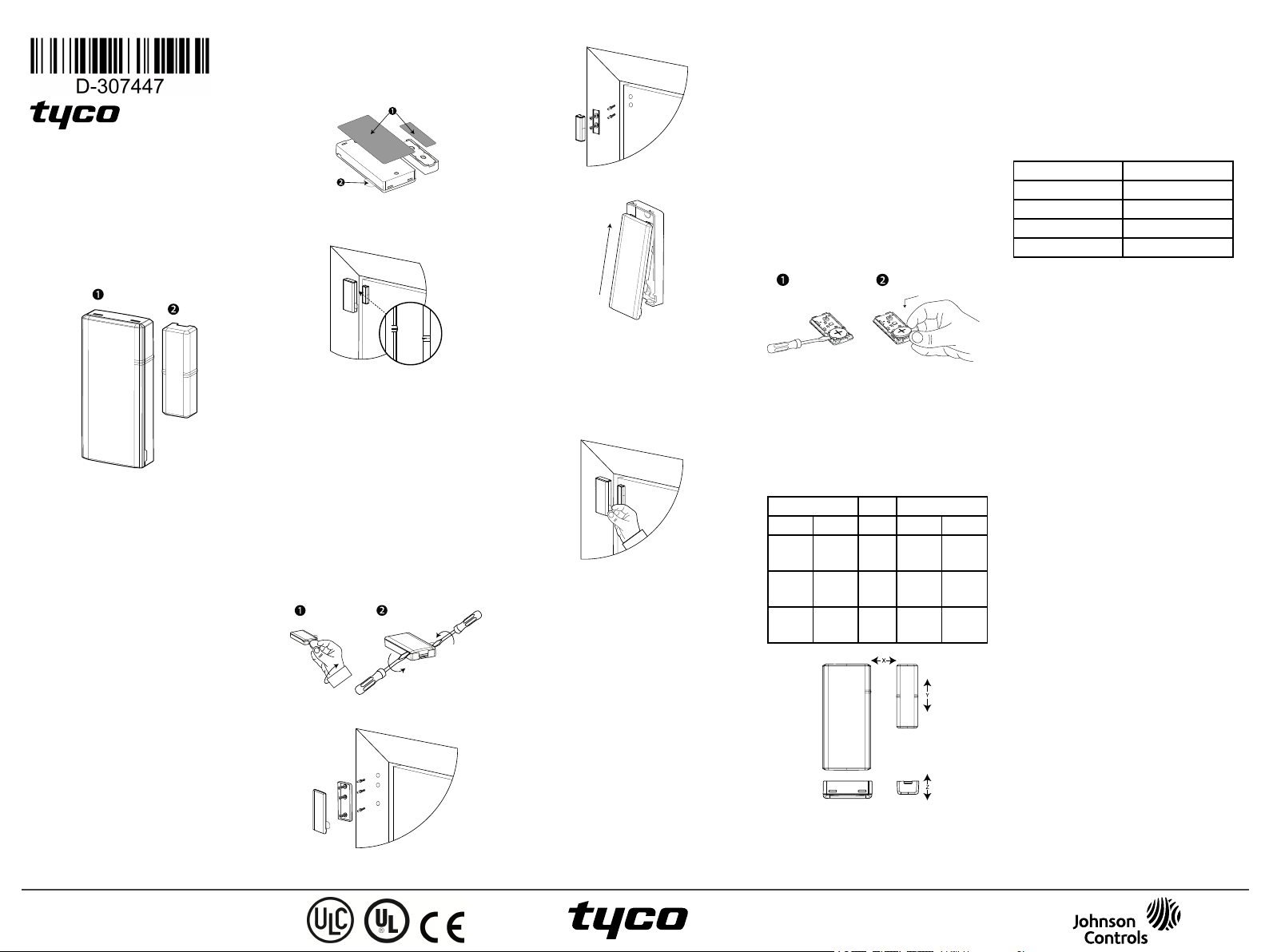
Figure 1:
PGx303
1: Device
2: Magnet
l Two-way PowerG communication with the control
panel
l Front a nd back cover tamper detec tion
l LED lightsignal strength indication during install-
ation
l Discre et transmission of supervision message
l PowerG two-way frequency hopping spre ad spec-
trum time-division multiple a cc ess (FHSS-TDMA)
technology
l Low battery indication
Installation
CAUTION! Ser vice personnel only may install this
equipme nt. Plac e this device in non-haz ar dous indoor
loca tions only.
NOTES:
Installthe PGx303 in acc ordanc e with the Standa rd
for Installation and Classification of Residential Burglar Alarm Systems,UL 1641.
To comply with FCC and IC RFe xposure compliance
requirements, locate the device a t a dista nce of at
least 20 cm from a ll persons dur ing normal opera tion.
Do not co-loca te the antennas used for this product, or
oper ate them in c onjunc tion with any other ante nna or
transmitter.
Mo unt in g t he d evice (q uick inst all ation)
NOTE: Do not use this method for UL installations as
UL cer tified devices mustbe mechanically secur ed.
1. Peel the relea se liners off the two strips of doublesided adhesive tape and attach the tape to the back
of the de vice and the magnet. See Figure 2.
2. Place the device on the frame of a window or
door and place the magnet on the moving surfa ce
of the door or window itself, directed according to
the location marks. See Figure 3.
NOTE:See Typic al re ed switch positions for more
information on a lignment.
Figure 2: Quick installation
1: Double- sided adhe sive tape
2: Enrollment / ba ttery tab
Figure 3: De vice andmagnet position on door and
Mo unt in g t he d evice (screw inst allat ion)
To mountthe de vice with sc re ws, comple te the following ste ps:
1. Insert a coin in the slot a nd twistto remove the
cover. See Figure 4.1. If a coin is not ava ilable,
insert a 4 mm f lat screwdr iver into each slot of the
plastic cover and twist to open e ach side. See Figure 4.2.
2. Screw the device base onto the door frame. See
Figure 5.
3. Screw the magnet base on to the door, aligning it
with the line on the device . See Figure 3.
NOTE: See Ty pical reed switch positions for
more informa tion on alignment
4. Clip the covers on to the device and magnet base
(see Figure 7).
door fr ame
Figure 4: Device cove r removal
Figure 5: De vice screw installation
Figure 6: Magnet scr ew installation
Figure 7: Closing the device cover
Enr ollin g t h e device
To enroll the device , complete the following steps:
NOTES:
Refe r to the pane l installer guide a nd follow the proce dure under the 02:ZONES/DEVICES option of the
installer menu.
For UL/ULC listed installations use only in conjunction
with U L/ULC listed control pane ls.
Figure 8: Battery/enrollment tab
Refe r to the pane l installation manual f or the enrollment procedure . A gene ra l descr iption of the proce dure is provide d be low:
1. To ensure that the prope r steps a re used, refer to
the installation manual for the alarm system that
the device is being e nrolled on.
2. Enter the device enrollment option through the spe cified method and se lect the appropriate option to
add the new device.
3. Enroll the device by either inserting the battery to
power on the de vice until the enrollment is dete cted, or by enter ing the device ID.
4. Select the desired zone number.
5. Configure any device para meters that are
required.
6. Mount a nd test the detector. See walk testing for
information on testing the de vice. In addition, see
the alarm systems installation manual that the
device is enrolled on for other test procedures that
are re quired.
If the detec tor is a lre ady enrolled, you can c onfigure
the detec tor par ame ters by programming the system,
see the alarm systems installation manual for more
information about device par ame ter s.
NOTE: W hen enrolling the de tec tor to WP panels
with version 19.4 or lower, the de tec tor is e nrolled as
ID:100-XXXX , and labele d Contact in the panel.
Rep lacing th e batt er y
CAUTION! Risk of explosion if battery is replaced by
an incorr ec t type. D ispose of used batteries acc ording
to the manufacturer's instructions.
WARNING! This product conta ins a coin ba tter y. If it
is swallowe d, it can c ause seve re interna l burns in just
2 hours and ca n lead to death. Ke ep new a nd used batterie s a wa y from c hildre n. If the batte ry compartment
does not close sec urely, stop using the produc t a nd
kee p it a wa y from c hildre n. If you think batter ies
might have be en swallowe d or placed inside any part
of the body, see k immediate me dica l attention.
To remove the batte ry, complete the following steps:
1. Remove the c over . See Figure 4.
2. Wedge a flat he ad screwdriver under the ba ttery.
See Figure 9.1.
3. Twist the screwdriver using the base as a lever to
remove the battery.
Figure 9: Battery removal and insert ion
To insert the battery, complete the following steps:
1. Insert the batter y at a n angle while observing battery polarity. See Figure 9.2.
2. Press down on the battery until it fits into place .
Typical reed switch positions
The following table displa ys the range cover age direc tions of the PGx303.
Table 1: Typical ree d switch positions
Wood Supports Iron
Opening Closing Direction Opening Closing
>22 mm
(0.87 in.)
> 16mm
(0.63 in.)
> 27mm
(1.06 in.)
< 19mm
(0.75 in.)
< 14mm
(0.55 in.)
< 25mm
(0.98 in.)
> 9 mm
(0.35 in.)
> 12mm
(0.47 in.)
> 18mm
(0.71 in.)
< 5 mm
(0.20 in.)
< 10mm
(0.40 in.)
< 15mm
(0.60 in.)
X
Y
Z
Figure 10: Range coverage directions
Local diagnostics test
Befor e testing, separ ate the cove r from the base (see
Figure 4), then complete the following steps:
1. Close the cove r to return the tamper switch to its
normal (undisturbed) position.
2. Momentarily open the door or window and verify
the red LED blinks, indica ting de tection.
3. After two seconds, one of the LEDs blinks three
times.
Table 2 displays received signal strength indication:
Table 2: Signalst re ngth indication
LED r esponse Rece ption
Green LED blinks Strong
Yellow LED blinks Good
Red LED blinks Poor
No blinks No communication
IMPORTANT! Reliable reception must be assured.
Ther ef ore , poor signal strength is not a cc eptable. If
you rece ive a poor signal from the detector , re-locate
it a nd re- test until a strong signal strength is re ce ived
(in regions re quiring UL-c ompliant installation, only
strong signal strength is pe rmitted).
NOTE: I t is r ec ommended to ha ve a strong signal
strength and you must ve rif y the signal stre ngth using
the control panel's diagnostic test. For deta iled Diagnostics Test instruc tions, refe r to the contr ol pa nel
installer guide .
Specifications
WIRELESS
Freque ncy: 433, 868, 915 (in accorda nce with the prevailing f re quency of your region).
Note:O nly device s in frequency band 912 MHz - 919
MHz are UL/ULC listed
Maximum Tx Power : +14 dBm r adia ted @ 868 MHz;
+10 dBm ra diate d @433 MHz
Modulation: GFSK
Antenna: Built-in inverted-F a ntenna
Communication protocol: Power G
Supervision: Signaling at 256 se cond interva ls
ELECTRICAL
Battery Type:3 V Lithium CR2450 Panasonic ba ttery
only
Battery Life: 6 year s with typic al use at room temperature 25°C (77°F)
NOTE: Not verified by UL
Low Battery Thr eshold: 2 V at room tempera ture 25°C
(77°F)
ENVIRONMENTAL
Operating tempera ture : -10°C(14°F ) to 55°C (131°F).
UL verified range: 0ºC (32°F) to 49ºC(120°F ) only
Storage Tempe ra ture : -20°C to 70°C (-4°F to 158°F)
Relative Humidity (RH): Up to 95% non-condensing,
UL verified up toa ma ximum of 85% RH only
PHYSICAL
Size (LxWxD): 67 mm x 31 mmx 11 mm (2.6 in. x 1.2
in. x 0.4 in.)
We ight (with batter y): 20 g (0.71 oz)
Color:White or Brown
UL /U LC No t es
Only model PG9303 ope ra ting in the f re quency band
912-919MHz is U L/cU L listed. The PG9303 has been
listed by UL/cUL f or c ommer cia l and r eside ntial burglary applications in acc orda nc e with the re quire ments
in the Standa rds UL 634 and ULC/ORD-C634 for contacts and switche s. For U L/ULC installations use these
devic e only in conjunction with compatible DSC wire less rece ivers: HSM2HOST9, HS2LCDRF(P)9,
HS2ICNRF(P)9, PG9920, WS900-19, and W S900- 29.
D-307447 PGx303
Installation Instructions
©2018 Tyco Security Products
www.dsc.com
Tech. Support: 1-800-387-3630
Afte r installation verify the produc t functiona lity in
conjunc tion with the c ompatible rec eive r used.
Europe: CE/EN (EN 300220, EN 301489,
EN 50130-4, EN 50130- 5, EN 61000- 6-3, EN 623681, EN50131-2-6 GRADE 2, CLASS I I, EN50131- 6
Type C) listed PG8303: 868 MHz PG4303:433 MHz .
Acc ording to EN 50131- 1, this equipment can be
applied in installed systems up to and including Security Grade 2, Environmental Class II .
UK: The PG8303 is suitable for use in systems
installed to conform to PD6662 at Gra de 2 and environmenta l cla ss II BS8243. The Power G periphe ra l
devic es have two-w ay c ommunica tion functionality,
providing additional benef its as described in the te chnica l brochure. This functiona lity ha s not been tested
to c omply with the respe ctive tec hnical requirements
and should there for e be conside re d outside the scope
of the produc t’s certific ation.
Simplified EU dec laration of conformity
Her eby, Tyc o Safety Produc ts Cana da Ltd. de clare s
that the radio equipment type is in complia nce with
Dire ctive 2014/53/EU.
The full te xt of the EU declara tion of conformity is
ava ilable at the following internet address:
PG4303: http://dsc.com/pdf/1809003
PG8303: http://dsc.com/pdf/1809004
Freque ncy band Maximum power
Frequen cy Max power
868.0 MHz - 868.6 MHz +14 dBm
868.7 MHz - 869.2 MHz +14 dBm
433.04 MHz - 434.79
MHz
European single point of conta ct: Tyco Safety
Products,
Voltaweg 20, 6101
XK Echt, Nether lands.
FC C C OM PL IA N CE ST ATEM EN T
WARNING! Cha nges or modifications to this unit not
expr essly appr oved by the par ty responsible for compliance could void the user’s author ity to ope ra te the
equipme nt. This device ha s been tested and found to
comply with the limits for a Class B digital device, pursuant to Part 15 of the FCCRule s. These limitsa re
designe d to pr ovide reasonable protec tion against
harmful inte rferenc e in residential installations. This
equipme nt gener ate s uses and c an r adiate ra dio frequenc y energy and, if not installed and use d in a ccor danc e with the instructions, ma y cause harmful
interf er ence to radio and television reception.
Howe ver, the re is no guarante e that interfe re nce will
not occur in a particular installation. If this de vice
does cause such interferenc e, w hich can be ve rified
by turning the de vice off and on, the user is encourage d to eliminate the interference by one or more of
the following measur es:
– Re-or ient or re-loca te the rec eiving antenna .
– Incre ase the distance be tween the device and the
rece iver .
– Connec t the device to an outlet on a cir cuit different
from the one tha t supplies power to the rec eive r.
– Consult the dealer or an expe rie nce d radio/TV technician.
FCCID: F5318PG9303
Indu stry Can ada St atemen t
This e quipment complies with FCC and ISED Canada
RF ra diation exposure limits set f orth for an uncontrolled environme nt. This device c omplies with FCC
Rules Part 15 and with ISED Canada lic enc e exempt
RSSsta ndard( s). Operation is subject to the following
two conditions: ( 1) This de vice may not cause harmful
interf er ence, and (2) this device must acc ept any interference that may be re ce ived or tha t may c ause
undesir ed operation.
Le present appa re il est c onforme aux CNR d'ISED
Canada applicables aux appar eils radio exempts de
+10 dBm
licence . L'exploitation est autorise e aux de ux conditions suivantes :(1) l'appa re il ne doit pas produire de
brouillage, et (2) l'utilisateur de l'appare il doit
ac ce pter tout brouillage ra dioelectrique subi, meme si
le brouillage est susc eptible d'en comprome ttre le fonctionnement.
To comply with FCC Sec tion 1.1310 for human exposure to r adio fre quency electromagne tic fields and IC
requirements, implement the following instruction: A
distance of at le ast 20c m be tween the equipment and
all persons should be maintained during the operation
of the e quipment. Le dispositif doit être pla cé à une
distance d'au moins 20 c m à partir de toutes les personnes au cours de son f onctionnement nor mal. Les
ante nnes utilisées pour ce produit ne doivent pas ê tre
situés ou exploité s conjointeme nt a vec une autr e
ante nne ou transme tteur.
IC: 160A-PG9303
The term IC before the ra dio c er tification numbe r signifies that the Industry Canada tec hnica l specific ations wer e met. This Class B digital appar atus
complies with Cana dian ICES-003. This device c omplies with RSS-247 of I ndustry Canada . Operation is
subjec t to the following two conditions: (1) this device
may not ca use inte rf er enc e, a nd (2) this device must
ac ce pt a ny inter fe re nce, including interferenc e that
may cause undesir ed operation of the devic e.
Cet appareil numérique de la c lasse B e st conf orme à
la norme NMB-003 du Canada. Ce dispositif satisfa it
aux exigence s d’Industrie Canada , pre scr ites dans le
docume nt CNR- 247. son utilisation est autorisée se ulement aux c onditions suiva ntes: ( 1) il ne doit pa s
produir e de brouillage et (2) l’utilisate ur du dispositif
doit ê tre prêt à ac cepter tout brouillage radioéle ctrique reç u, même si c e brouillage e st susce ptible de compromettre le fonctionne ment du
dispositif.
Limit ed W ar ran t y
Digital Secur ity Controls (DSC) warrants that for a
period of 12 months f rom the date of purcha se, the
produc t sha ll be free of defec ts in mate ria ls and workmanship under norma l use and that in fulfilment of any
breac h of such warranty, DSCshall, at its option,
repair or re plac e the defec tive equipme nt upon return
of the e quipment to itsrepair de pot. This war ra nty
applies only to defe cts in parts and workmanship and
not to damage incurre d in shipping or handling, or
dama ge due to causes beyond the control of D SC such
as lightning, e xcessive voltage, mec hanical shock,
wate r damage , or damage arising out of abuse , alter ation or improper a pplica tion of the equipment. The
foregoing warranty shall apply only to the original
buyer , a nd is and shall be in lieu of any and all other
war ra nties, whether e xpre ssed or implied and of a ll
other obligations or liabilities on the par t of DSC.
Digital Secur ity Controls neither assumes responsibilityfor, nor authoriz es any othe r person purporting
to a ct on its behalf to modify or to change this warranty, nor to assume for it any other warra nty or liability concerning this product. In no e vent shall DSC be
liable for any direct, indire ct or consequential damage s, loss of anticipate d profits, loss of time or any
other losses incurred by the buyer in connec tion with
the purcha se, installation or operation or failure of this
produc t. W ARNING: DSC rec ommends that the entire
system be c ompletely tested on a regula r basis.
Howe ver, de spite fr equent testing, and due to, but not
limited to, criminal tampering or elec trical disruption,
it is possible for this product to f ail to perf orm as
expe cte d. Importa nt Infor mation: Changes/modifica tions not expr essly approve d by DSC could
void the user’s authority to operate this equipment.
IMPORTANT READ CAREFULLY: DSC Software
purc hase d with or without Products and Components is
copyr ighted and is pur cha sed under the following
license te rms:
This End User License A gre eme nt ("EULA") is a
lega l agre eme nt between You (the company,
individual or entity who a cquired the Softwar e and
any rela ted Ha rdware) and D igital Secur ity Controls,
a division of Tyco Safety Produc ts Canada Ltd.
("DSC"), the manuf ac ture r of the integra ted sec urity
systems a nd the deve loper of the softwa re a nd any
related products or compone nts ("HARDW ARE")
which You ac quire d.
If the DSC software produc t ("SOFTW ARE
PRODUCT" or "SOFTWARE") is intended to be
ac compa nied by HARDWARE, and is NOT accompanie d by new HARDW ARE, You may not use , copy
or install the SOFTWARE PRODUCT. The
SOFTWARE PRODUCT include s computer sof tware,
and may include assoc iated media, printe d mater ials,
and "online" or e lec tronic documentation.
Any softwar e provided along with the SOFTWARE
PRODUCT tha t is a ssocia ted with a sepa ra te end user
license a greement is license d to You under the terms
of that license a gre ement.
By insta lling, copying, downloading, storing, accessing
or otherwise using the SOFTWARE PRODUCT, You
agree unconditionally to be bound by the terms of this
EULA, e ven if thisEULA is deeme d to be a modifica tion of any previous arrange ment or contract. If
You do not a gre e to the te rms of this EULA, DSC is
unwilling to lice nse the SOFTWARE PRODUCT to
You, and You have no right to use it.
SOFTWARE PRODUCT LICENSE
The SOFTWARE PRODUCT is pr otec ted by copyright laws a nd international copyright trea ties, as w ell
as other intellectua l property laws a nd tre aties. The
SOFTWARE PRODUCT is licensed, not sold.
1. GRANT OF LICENSE. This EULA gra nts You the
following rights:
(a) Softwa re I nstallation a nd Use - For ea ch license
You acquir e, You may have only one copy of the
SOFTWARE PRODUCT installed.
(b) Storage /Network Use - The SOFTWARE
PRODUCT ma y not be insta lled, acce ssed, displaye d,
run, share d or used concurrently on or from different
compute rs, including a worksta tion, terminal or other
digital e lec tronic device ( "Device "). In other words, if
You have sever al wor kstations, You will have to
ac quire a lice nse for eac h workstation wher e the
SOFTWARE will be use d.
(c) Backup Copy - You may make ba ck up c opies of
the SOFTWARE PRODUCT, but You may only have
one copy per lice nse installed at any given time. You
may use the back up copy solely for arc hival purposes. Except as expressly provided in this EULA,
You may not otherw ise make copie s of the
SOFTWARE PRODUCT, including the pr inted mate rials accompanying the SOFTWARE.
2. DESCRIPTION OF OTH ER RIGHTS AND
LIMITATI ONS
(a) Limitations on Rever se Engine ering, Decompilation a nd Disassembly - You may not re ver se enginee r, decompile , or disassemble the SOFTWARE
PRODUCT, e xcept and only to the exte nt tha t such
ac tivityis expr essly per mitted by a pplica ble law notwithstanding this limitation. You may not make any
cha nges or modifica tions tothe Software, without the
written permission of an offic er of DSC. You may not
remove any propr ietary notices, mar ks or labels from
the Software Product. You shall institute reasonable
measures to ensure complianc e with the terms and
conditions of thisEULA .
(b) Separ ation of Components - The SOFTWARE
PRODUCT is license d as a single produc t. Its c omponent parts may not be separated for use on more
than one HARDWARE unit.
(c) Single INTEGRATED PRODUCT - If You
ac quire d this SOFTWARE with HARDWARE, then
the SOFTWARE PRODUCT is lice nsed with the
HARDW ARE a s a single integr ate d product. In this
ca se, the SOFTWARE PRODUCT may only be used
with the HARDWARE as set forth in this EU LA.
(d) Rental - You may not r ent, lease or lend the
SOFTWARE PRODUCT. You may not make it available to othe rs or post it on a se rve r or web site.
(e) Softwa re Product Tra nsfe r - You may transfer a ll
of Your rights under this EULA only as pa rt of a permane nt sale or transfer of the HARDW ARE, provide d
You retain no c opies, You transfer all of the
SOFTWARE PRODUCT (including all compone nt
parts, the media and printed ma ter ials, a ny upgrades
and this EULA), and provided the re cipie nt agre es to
the terms of thisEULA . If the SOFTWARE
PRODUCT is a n upgrade , any transfer must also
include all prior versions of the SOFTWARE
PRODUCT.
(f) Termination - Without prejudic e to a ny othe r
rights, D SC may te rminate this EULA if You fa il to
comply with the terms and conditions of this E ULA. In
such event, You must de stroy all copies of the
SOFTWARE PRODUCT and a ll of its component
parts.
(g) Tra dema rks - This EULA does not grant You any
rights in c onne ction with a ny trade marks or se rvic e
marks of DSC or its suppliers.
3. COPYRIGH T
All title a nd intellectua l property rights in and to the
SOFTWARE PRODUCT (including but not limited to
any images, photogr aphs, a nd text incorpora ted into
the SOFTWARE PRODUCT), the acc ompanying printed materia ls, and any copie s of the SOFTWARE
PRODUCT, a re owne d by DSC or its suppliers. You
may not copy the printed materials accompanying the
SOFTWARE PRODUCT. All title a nd intelle ctua l property rights in and to the content which may be
ac ce ssed through use of the SOFTWARE PRODUCT
are the pr operty of the respec tive conte nt owner and
may be protecte d by applic able copyright or other
intellec tual prope rty laws and tre atie s. This EULA
grants You no rights touse such content. All r ights not
expr essly gra nted under this EULA ar e rese rve d by
DSC and its suppliers.
4. EXPORT RESTRICTIO NS
You agre e that You will not export or re expor t the
SOFTWARE PRODUCT to any country, person, or
entity subject to Cana dian export re strictions.
5. CHOICE OF LAW: This Softwa re License Agree ment isgover ned by the laws of the Province of
Ontar io, Canada .
6. ARBITRATION
All disputes arising in connec tion with this Agree ment
shall be de ter mined by final a nd binding ar bitration in
ac cor dance with the Arbitration Act, and the parties
agree to be bound by the arbitra tor's decision. The
plac e of a rbitration sha ll be Tor onto, Canada , and the
langua ge of the arbitra tion shall be English.
7. LIMITED W ARRANTY
(a) NO W ARRANTY
DSC PROVIDES THE SOFTWARE "AS IS"
WITHOU T W ARRANTY. DSC DOES NOT
WARRANT TH AT TH E SOFTWARE WILL MEET
YOUR REQUIREMENTS OR THAT OPERATION
OF THE SOFTWARE WILL BE U NINTERRUPTED
OR ERROR-FREE.
(b) CHANGES IN OPERATING ENV IRONMENT
DSC sha ll not be re sponsible for problems cause d by
cha nges in the operating cha ra cte ristics of the
HARDW ARE, or for problems in the interaction of
the SOFTWARE PRODUCT with non- D SCSOFTWARE or HARDWARE PRODUCTS.
(c) LIMITATION OF LIABILI TY; WARRANTY
REFLECTSALLOCATIO N OF RISK
IN ANY EVENT, IF ANY STATUTE IMPLIES
WARRANTIES OR CONDITIONS NOT STATED
IN THIS LICENSE AGREEMEN T, DSC'S ENTIRE
LIABILITY UNDER ANY PROVISIO N OF TH IS
LICENSE AGREEMENT SHALL BE LIMITED TO
THE GREATER OF THE AMOUNT ACTUALLY
PAID BY YO U TO LICENSE THE SOFTWARE
PRODUCT AND FIVE CANAD IAN DOLLA RS
(CAD$5.00). BECAUSE SOME JURISDICTIONS DO
NOT ALLOW THE EXCLUSION OR LIMITATI ON
OF LIABILITY FOR CONSEQU ENTIAL O R
INCIDENTAL DAMAG ES, THE ABOVE
LIMITATI ON MAY NOT APPLY TO YOU.
(d) DISCLAI MER OF WARRANTIE S
THIS WA RRANTY CONTAINS THE ENTIRE
WARRANTY A ND SHALL BE IN LIEU OF ANY
AND ALL OTHER WA RRANTIES, WHETHER
EXPRESSED OR IMPLIED (INCLUDING ALL
IMPLIED W ARRANTIES OF MERCHANTABILITY
OR FITNESS FOR A PARTICULAR PURPOSE) AND
OF A LL OTHER OBLIGATI ONS OR LI ABILITI ES
ON THE PART OF DSC. DSC MAKES NO OTHER
WARRANTIES. DSCNEITHER ASSUMES NOR
AUTH ORIZES A NY OTHER PERSON
PURPORTING TO ACT ON ITS BEHA LF TO
MODIFY OR TO CHANGE THI S WARRANTY,
NOR TO ASSUME FORIT ANY OTHER
WARRANTY O R LIABILITY CONCERNING THIS
SOFTWARE PRODUCT.
(e) EXCLUSIVE REMEDY A ND LIMITATION OF
WARRANTY
UNDER NO CIRCUMSTANCES SHALL DSC BE
LIABLE FOR ANY SPECIAL, INCIDENT AL,
CONSEQUENTI AL OR INDI RECT DAMAGES
BASED U PON BREACH OF WARRANTY,
BREACH OF CONTRACT, NEGLIGENCE, STRICT
LIABILITY, OR ANY OTHER LEGAL THE ORY.
SUCH DAMAGES INCLUDE, BUT ARE NOT
LIMITED TO, LOSS OF PROFITS, LOSS OFTHE
SOFTWARE PRODUCT OR ANY ASSOCIATED
EQUI PMENT, COST OF CAPITA L, COST OF
SUBSTITUTE OR REPLACEMENT EQUIPMENT,
FACILITIES OR SERVICES, D OWN TIME,
PURCHASERS TI ME, THE CLAIMS OaF THI RD
PARTIES, INCLUDING CUSTOMERS, AND
INJURY TO PROPERTY.
WARNING: DSC rec ommends that the e ntire system
be complete ly tested on a r egular ba sis. Howe ver , despite frequent testing, and due to, but not limited to,
criminal tampe ring or e lec tric al disruption, it is possible for this SOFTWARE PRODUCT to fail to perform as e xpe cte d.
D-307447 PGx303
Installation Instructions
©2018 Tyco Security Products
www.dsc.com
Tech. Support: 1-800-387-3630
PGx303 Instructions d'installation
Co ntact magn ét ique invi sib le géré
Panorama
Le PGx303 est un éme tteur à contac t magnétique
PowerG minc e e t tr ès longue duré e, c ompatible avec
les centrales WP. L'appareil sans fil intègre un interrupteur magné tique qui ouvre un circuit lorsque
l'aimant e st dépla cé par rapport à sa position nor male .
REMARQUE: le x da ns le nom du produit pe ut êtr e
remplacé pa r l'un des nombre s suivants: 4,8,9. 4 correspond à la fré quence 433 MHz, 8 à 868 MHz et 9 à
912 MHz - 919 MHz.
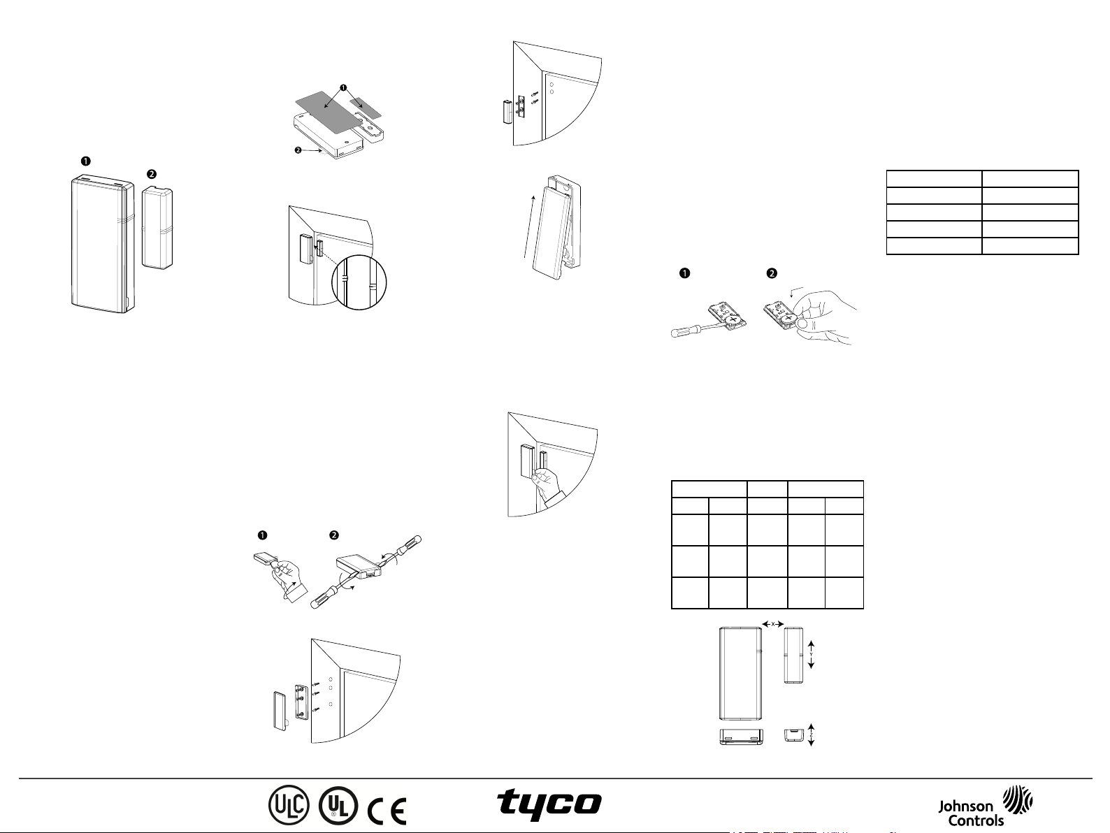
Figure 1:
PGx303
1: Appar eil
2:Aimant
Le détecteur présente les c ar ac tér istiques suivantes:
l Communication Power G bidirectionnelle a vec la
centrale
l Détection de l'autoprotec tion a vant et arrière
l Le voyant s'éclaire en ver t, jaune ou rouge
pendant l'installation, en fonction de la puissance
du signal
l Il ne s'allume pas pendant l'émission d'un message
de supervision
l Technologie bidirec tionnelle PowerG Frequenc y
Hopping Spread Spectrum FHSS-TDMA
l Lorsque la pile e st faible, un message «batterie
faible» est envoyé au récepteur
Installation
AVERTISSEMENT! Cet équipeme nt devra être
installé par un technic ien de ma intena nce en intérieur ,
à un e mplac eme nt non dange re ux uniquement.
REMARQUES:
Le PGx303 sera installé confor méme nt à la norme UL
1641, Norme pour les Insta llations et le s Classifica tions des Systèmes d'Alarme Antivol Résidentiels.
Pour des raisons de c onformité aux normes d'exposition aux fré que nce s radio FCC et I C, l'appar eil
doit ê tre distant d'au moins 20 c m de toute personne,
en conditions de fonctionne ment nor males.
Les antennes utilisées pour ce produit ne doive nt pas
être positionnées dans un même espa ce, ni utilisées
ave c une autre a ntenne ou émetteur .
Mo ntage de l' appareil (inst allation rap id e)
REMARQUE: N'utilisez pas cette méthode pour les
installations UL, car le s appareils cer tifiés UL doivent
être séc urisés méca niquement.
1. Retirez les protections des de ux bandes adhésives
double-face et f ixez- les à l'arrière de l'appareil et
de l'aimant. Voir la Figure 2.
2. Positionnez l'appareil sur le dormant d'une fenêtre
ou d'une porte et l'aimant sur la partie mobile de la
porte ou de la fenê tre, alignés sur les repères. Voir
la Figure 3.
REMARQUE:Pour plus d'informations sur l'alignement, voir Positions courantes de l'interrupte ur m ag-
nétique .
Figure 2: Installation rapide
1: Bande adhésive double fa ce
2: Langue tte d'enre gistre ment
Figure 3: De vice andmagnet position on door and
Mo ntage de l' appareil (inst allation avec vis)
Pour monter l'appareil avec des vis, procé dez comme
suit:
1. Insérez une pièce dans la fente et tournez pour
retire r le capot. Voir la Figure 4.1. Si vous n'avez
pas de pièce, insérez un tournevis plat de 4mm
dans chaque fente du capot en plastique, et
tournez pour ouvrir chaque côté du capot. Voir la
Figure 4.2.
2. Vissez le socle de l'appareil sur le dormant. Voir la
Figure 5.
3. Vissez le socle de l'aimant sur la porte, en prenant
soin de l'aligner sur le récepteur. Voir la Figure 3.
REMARQUE:Pour plus d'informations sur
l'alignement, voir Positions c ourante s de l'in-
terrupte ur magnétique .
4. Fixez les capots sur le socle de l'appareil et sur
celui de l'aimant. Voir la Figure 7.
door fr ame
Figure 4: Device cove r removal
Figure 5: De vice screw installation
Figure 6: Magnet scr ew installation
Figure 7: Closing the device cover
Enr egi strement d e l'ap par eil
Pour enregistrer l'appa re il, allez dans le menu 'Installation' de la centrale e t procédez c omme suit:
REMARQUES:
Consultez le Guide de l'installateur de la centr ale e t
suivez la procé dure indiqué e pour l'option
02:ZONES/APPAREILSdu Menu Installate ur.
Dans le ca s d'installations confor mes UL/ULC, utilisez
uniqueme nt le détecteur avec des ce ntra les certifié es
UL/ULC.
Figure 8: Battery/enrollment tab
Consultez le manuel d'installation du système d'ala rme
dans lequel l'appa re il est enregistré af in de suivre la
proc édure adéqua te:
1. Utilisez la méthode préconisée pour accéder à l'option d'enregistrement de l'appar eil et sélectionnez
l'option c orrespondante pour ajouter un nouvel
appareil.
2. Enregistrez l'appareil, soit en insér ant la pile pour
mettre l'appareil sous tension jusqu'à ce que l'enregistrement soit dé tecté , soit e n saisissant l'ID de
l'appareil.
3. Sélectionnez le numéro de zone voulu.
4. Configurez les paramètres néce ssaire s de l'appare il.
5. Montez et testez le dé tecteur.
If the detec tor is a lre ady enrolled, you can c onfigure
the detec tor par ame ters by programming the system,
see the alarm systems installation manual for more
information about device par ame ter s.
REMARQUE: Lorsde l’enregistrement du détecteur
dans les c entrale s PowerMa ster dotéesde la ver sion
19.4 ou infé rie ure , celui-ci e st enr egistré en tant que
déte cte ur de mouvements (ID:100- XXXX) et identifié par Sens.contact dans la ce ntra le.
Rem placer la bat t erie
AVERTISSEMENT! Risque d'explosion si vous remplac ez la pile par une pile de type incorrect. Mettez
les piles usagée s a u rebut en suivant les instructions du
fabricant.
AVERTISSEMENT! Ce produit contient une pile
bouton. L'ingestion de la pile bouton pe ut entraîne r de
graves blessures internes en se ulement 2 heur es et
entraîner la mort. Conser vez les piles neuves et
usagé es hors de portée des enfa nts. Sile c ompar timent
de la pile ne fe rme pas correctement, a rr ête z d'utiliser
le produit et conservez -le hors de portée de s enfants.
Si vous pensez que des piles peuvent avoir été avalées
ou introduites dans une partie du cor ps, consulte z
immédiate ment un médec in.
Pour retirer la pile, procéde z comme suit:
1. Retirez le capot. Voir la Figure 4.
2. Glissez la lame d'un tournevis plat sous la pile.
Voir la Figure 9.1.
3. Faites pivoter le tournevis en vous aidant du socle
pour faire levier, afin de retirer la pile.
Figure 9: Re tr ait et insert ion de la pile
Pour insérer la pile, procé dez c omme suit:
1. Insérez la pile e n l'inclinant, le pôle (+) étant orienté vers le haut. Voir la Figure 9.2.
2. Appuyez sur la pile jusqu'à ce qu'elle s'enclenche .
Positions courantes de l'interrupteur magnétique
Consultez le Table au 1 pour savoir comment positionner le sur une surfac e en bois ou en f er :
Tableau 1: Positions courantes de l'inter rupteur
Bois Supports Fer
Ouverture Fermeture Axe O uverture F ermeture
>22 mm
(0.87 in.)
> 16mm
(0.63 in.)
> 27mm
(1.06 in.)
< 19mm
(0.75 in.)
< 14mm
(0.55 in.)
< 25mm
(0.98 in.)
magnét ique
X
Y
Z
> 9 mm
(0.35 in.)
> 12mm
(0.47 in.)
> 18mm
(0.71 in.)
< 5 mm
(0.20 in.)
< 10mm
(0.40 in.)
< 15mm
(0.60 in.)
Figure 10: Range coverage directions
Test de diagnostic local
Avant de proc éder au test, séparez le ca pot du socle.
Remar que: Voir la Figure 4.
1. Fermez le capot pour remettre le commutateur
d'autoprotection en position norma le (pas d'infra ction).
2. Ouvrez momentanément la porte ou la fenêtre et
vérifiez que le voya nt ROUGE clignote pour signaler la détection.
3. Au bout de deux secondes, un des voyants clignote
trois f ois.
Tableau 2: Indication de la qualité de la r éc eption
Voyant Réce ption
Voyant vert clignotant Fort
Voyant jaune clignotant Bon
Voyant rouge clignotant Faible
Aucun clignotement Pas de comm.
IMPORTANT! Vous devez vous a ssure r que la
réce ption est f iable . Par conséquent, une puissance de
signal faible est inacc eptable. Si vous rec eve z un signal faible du détecteur, changez -le d'emplace ment et
recommence z les tests jusqu'à obtenir un signal bon ou
fort (lorsque l'installation doit être certifiée UL, seul
un signal fort est autorisé) .
REMARQUE: Il est c onseillé d'obtenir un signal f ort
et vous devez vérifier sa puissance e n procédant à un
test de dia gnostic de la ce ntra le. Pour de s instr uctions
déta illées du test de diagnostic , consultez le Guide de
l'installateur de la centrale.
Specifications
SANS FIL
Bande de fréquenc es (MHz): 433, 868, 915 (selon la
fré que nce la plus utilisée dans votre région)
Remar que:Seuls les appa re ils utilisant la bande de
fré que nce s 912 MHz - 919 MHz sont certifiés
UL/ULC
Puissance d'émission max: +14 dBm é mis à 868 MHz;
+10 dBm émis à 433 MHz
Modulation: GFSK
Antenne: Antenne en F inversé intégré e
Protocole de communication: PowerG
Supervision: Signaux espac és de 256 s
ÉLECTRIQUE
Type de pile:Pile 3 V Lithium CR2450 Pana sonic
uniqueme nt
Autonomie: 6 ans dans le cadre d'une utilisation courante à tempér ature de la pièc e (25°C)
REMARQUE: non vérifié pa r UL
Seuil pile f aible : 2 V à température de la pièc e
(25°C).
ENVIRONMENTAL
Tempé ra ture en fonctionnement: -10°C à 55°C. Plage
ce rtifié e UL: 0ºCà 49ºC unique ment
Tempé ra ture en stocka ge: -20°C to70°C
Humidité r ela tive (HR): Jusqu'à 95% sans condensa tion, cer tifié UL jusqu'à une HR maximale de
85% uniquement
PHYSIQUE
Dimensions (LxlxP): 67 mm x 31 mm x 11 mm (2.6 in.
x 1.2 in. x 0.4 in.)
Poids (a vec pile): 20 g (0.71 oz )
Color:Blanc ou brun
Rem arq ues UL/ULC
Le PG303 e st homologué UL pour les a pplica tions
commerciales et résidentielles a nti-intrusion et homologué ULC pour les applica tions ré sidentie lles antiintrusion conformément à la, réglementation des
D-307447 PGx303
Installation Instructions
©2018 Tyco Security Products
www.dsc.com
Tech. Support: 1-800-387-3630
 Loading...