

Tyco Safety Canada 18LE2077 User Manual

LE2077
HSPA/3G Wireless Alarm Communicator
SCW 3G Communicator – North America
TL2553G
Ethernet/Internet and HSPA/3G Dual-Path Alarm Communicator
SCW 3G / Ethernet Communicator - North America
Installation Manual
v5.0
Warning: This manual contains information on limitations regarding product use and function
and information on the limitations as to liability of the manufacturer.


Table of Contents
Warning: Installer Please Read Carefully. . . . . . . . . . . . . . . . . . . . . . . . . . . . . . . . . . . . . . . . . . . . . . . . . . . . . . . . . . . . . . . . . . . . . . . . . . . . . . . . . 5
Mounting Considerations . . . . . . . . . . . . . . . . . . . . . . . . . . . . . . . . . . . . . . . . . . . . . . . . . . . . . . . . . . . . . . . . . . . . . . . . . . . . . . . . . . . . . . . . . . . . . . . 7
Communicator Technical Specifications . . . . . . . . . . . . . . . . . . . . . . . . . . . . . . . . . . . . . . . . . . . . . . . . . . . . . . . . . . . . . . . . . .7
General Information . . . . . . . . . . . . . . . . . . . . . . . . . . . . . . . . . . . . . . . . . . . . . . . . . . . . . . . . . . . . . . . . . . . . . . . . . . . . . . . . . . . . . . . . . . . . . . . . . . . . 7
Features . . . . . . . . . . . . . . . . . . . . . . . . . . . . . . . . . . . . . . . . . . . . . . . . . . . . . . . . . . . . . . . . . . . . . . . . . . . . . . . . . . . . . . . . . . . . . . . . . . . . . . . . . . . . . . . . 8
UL/ULC Installation Requirements. . . . . . . . . . . . . . . . . . . . . . . . . . . . . . . . . . . . . . . . . . . . . . . . . . . . . . . . . . . . . . . . . . . . . . . . . . . . . . . . . . . . . . 8
Communicator Frequency Bands for North America . . . . . . . . . . . . . . . . . . . . . . . . . . . . . . . . . . . . . . . . . . . . . . . . . . . . . . . . . . . . . . . . . . . . 9
Ratings . . . . . . . . . . . . . . . . . . . . . . . . . . . . . . . . . . . . . . . . . . . . . . . . . . . . . . . . . . . . . . . . . . . . . . . . . . . . . . . . . . . . . . . . . . . . . . . . . . . . . . . . . . . . . . . . . 9
Hardware Compatibility. . . . . . . . . . . . . . . . . . . . . . . . . . . . . . . . . . . . . . . . . . . . . . . . . . . . . . . . . . . . . . . . . . . . . . . . . . . . . . . . . . . . . . . . . . . . . . . . . 9
Communicator Pre Installation Configuration . . . . . . . . . . . . . . . . . . . . . . . . . . . . . . . . . . . . . . . . . . . . . . . . . . . . . . . . . . . 10
C24 Communications™ Account and SIM card Activation. . . . . . . . . . . . . . . . . . . . . . . . . . . . . . . . . . . . . . . . . . . . . . . . . . . . . . . . . . . . .10
Encryption . . . . . . . . . . . . . . . . . . . . . . . . . . . . . . . . . . . . . . . . . . . . . . . . . . . . . . . . . . . . . . . . . . . . . . . . . . . . . . . . . . . . . . . . . . . . . . . . . . . . . . . . . . . . .10
Communicator Configuration with SCW . . . . . . . . . . . . . . . . . . . . . . . . . . . . . . . . . . . . . . . . . . . . . . . . . . . . . . . . . . . . . . . . 11
Installation Location . . . . . . . . . . . . . . . . . . . . . . . . . . . . . . . . . . . . . . . . . . . . . . . . . . . . . . . . . . . . . . . . . . . . . . . . . . . . . . . . . . . . . . . . . . . . . . . . . . .11
Installing CAT 5 Cable (TL2553G only) . . . . . . . . . . . . . . . . . . . . . . . . . . . . . . . . . . . . . . . . . . . . . . . . . . . . . . . . . . . . . . . . . . . . . . . . . . . . . . . .12
Inserting/Removing the SIM Card . . . . . . . . . . . . . . . . . . . . . . . . . . . . . . . . . . . . . . . . . . . . . . . . . . . . . . . . . . . . . . . . . . . . . . . . . . . . . . . . . . . . .12
Communicator Reset . . . . . . . . . . . . . . . . . . . . . . . . . . . . . . . . . . . . . . . . . . . . . . . . . . . . . . . . . . . . . . . . . . . . . . . . . . . . . . . . . . . . . . . . . . . . . . . . . .13
Establishing a Communication Channel with the SCW Panel. . . . . . . . . . . . . . . . . . . . . . . . . . . . . . . . . . . . . . . . . . . . . . . . . . . . . . . . . . .13
SMS Command and Control Functions . . . . . . . . . . . . . . . . . . . . . . . . . . . . . . . . . . . . . . . . . . . . . . . . . . . . . . . . . . . . . . . . . . . . . . . . . . . . . . . .14
Label Programming for SMS Message . . . . . . . . . . . . . . . . . . . . . . . . . . . . . . . . . . . . . . . . . . . . . . . . . . . . . . . . . . . . . . . . . . . . . . . . . . . . . . . . . 15
Communicator Placement Test . . . . . . . . . . . . . . . . . . . . . . . . . . . . . . . . . . . . . . . . . . . . . . . . . . . . . . . . . . . . . . . . . . . . . . . . . . . . . . . . . . . . . . . .15
General Information. . . . . . . . . . . . . . . . . . . . . . . . . . . . . . . . . . . . . . . . . . . . . . . . . . . . . . . . . . . . . . . . . . . . . . . . . . . . . . . . . . . . 16
Keypad Data Display. . . . . . . . . . . . . . . . . . . . . . . . . . . . . . . . . . . . . . . . . . . . . . . . . . . . . . . . . . . . . . . . . . . . . . . . . . . . . . . . . . . . . . . . . . . . . . . . . . .16
Entering Data From Keypad. . . . . . . . . . . . . . . . . . . . . . . . . . . . . . . . . . . . . . . . . . . . . . . . . . . . . . . . . . . . . . . . . . . . . . . . . . . . . . . . . . . . . . . . . . . .16
Entering ASCII Characters . . . . . . . . . . . . . . . . . . . . . . . . . . . . . . . . . . . . . . . . . . . . . . . . . . . . . . . . . . . . . . . . . . . . . . . . . . . . . . . . . . . . . . . . . . . . .16
ETHERNET/Cellular Programming Options . . . . . . . . . . . . . . . . . . . . . . . . . . . . . . . . . . . . . . . . . . . . . . . . . . . . . . . . . . . . . 17
System Options. . . . . . . . . . . . . . . . . . . . . . . . . . . . . . . . . . . . . . . . . . . . . . . . . . . . . . . . . . . . . . . . . . . . . . . . . . . . . . . . . . . . . . . . . . . . . . . . . . . . . . . .17
Programming Options . . . . . . . . . . . . . . . . . . . . . . . . . . . . . . . . . . . . . . . . . . . . . . . . . . . . . . . . . . . . . . . . . . . . . . . . . . . . . . . . . . . . . . . . . . . . . . . . .20
Communications Reporting Codes. . . . . . . . . . . . . . . . . . . . . . . . . . . . . . . . . . . . . . . . . . . . . . . . . . . . . . . . . . . . . . . . . . . . . . . . . . . . . . . . . . . . .25
System Test Options [026 - 029] . . . . . . . . . . . . . . . . . . . . . . . . . . . . . . . . . . . . . . . . . . . . . . . . . . . . . . . . . . . . . . . . . . . . . . . . . . . . . . . . . . . . . .25
Ethernet Receiver 1 Options . . . . . . . . . . . . . . . . . . . . . . . . . . . . . . . . . . . . . . . . . . . . . . . . . . . . . . . . . . . . . . . . . . . . . . . . . . . . . . . . . . . . . . . . . . .27
Ethernet Receiver 2 Options . . . . . . . . . . . . . . . . . . . . . . . . . . . . . . . . . . . . . . . . . . . . . . . . . . . . . . . . . . . . . . . . . . . . . . . . . . . . . . . . . . . . . . . . . . .28
Ethernet Options. . . . . . . . . . . . . . . . . . . . . . . . . . . . . . . . . . . . . . . . . . . . . . . . . . . . . . . . . . . . . . . . . . . . . . . . . . . . . . . . . . . . . . . . . . . . . . . . . . . . . . .29
Cellular Receiver 1 Options . . . . . . . . . . . . . . . . . . . . . . . . . . . . . . . . . . . . . . . . . . . . . . . . . . . . . . . . . . . . . . . . . . . . . . . . . . . . . . . . . . . . . . . . . . . .29
Cellular Receiver 2 Options . . . . . . . . . . . . . . . . . . . . . . . . . . . . . . . . . . . . . . . . . . . . . . . . . . . . . . . . . . . . . . . . . . . . . . . . . . . . . . . . . . . . . . . . . . . .30
Cellular Options. . . . . . . . . . . . . . . . . . . . . . . . . . . . . . . . . . . . . . . . . . . . . . . . . . . . . . . . . . . . . . . . . . . . . . . . . . . . . . . . . . . . . . . . . . . . . . . . . . . . . . . .31
Command and Control Options . . . . . . . . . . . . . . . . . . . . . . . . . . . . . . . . . . . . . . . . . . . . . . . . . . . . . . . . . . . . . . . . . . . . . . . . . . . . . . . . . . . . . . . .32
SMS Command and Control Functions . . . . . . . . . . . . . . . . . . . . . . . . . . . . . . . . . . . . . . . . . . . . . . . . . . . . . . . . . . . . . . . . . . . . . . . . . . . . . . . .33
SMS Command and Control Response . . . . . . . . . . . . . . . . . . . . . . . . . . . . . . . . . . . . . . . . . . . . . . . . . . . . . . . . . . . . . . . . . . . . . . . . . . . . . . . .35
Receiver Diagnostic Testing . . . . . . . . . . . . . . . . . . . . . . . . . . . . . . . . . . . . . . . . . . . . . . . . . . . . . . . . . . . . . . . . . . . . . . . . . . . . . . . . . . . . . . . . . . .37
System Information (Read Only) . . . . . . . . . . . . . . . . . . . . . . . . . . . . . . . . . . . . . . . . . . . . . . . . . . . . . . . . . . . . . . . . . . . . . . . . . . . . . . . . . . . . . . .37
System Reset Defaults . . . . . . . . . . . . . . . . . . . . . . . . . . . . . . . . . . . . . . . . . . . . . . . . . . . . . . . . . . . . . . . . . . . . . . . . . . . . . . . . . . . . . . . . . . . . . . . . .38
Communicator Troubleshooting . . . . . . . . . . . . . . . . . . . . . . . . . . . . . . . . . . . . . . . . . . . . . . . . . . . . . . . . . . . . . . . . . . . . . . . . . . . . . . . . . . . . . . .38
Ethernet/Cellular Programming Worksheets . . . . . . . . . . . . . . . . . . . . . . . . . . . . . . . . . . . . . . . . . . . . . . . . . . . . . . . . . . . 43
End User Licence Agreement . . . . . . . . . . . . . . . . . . . . . . . . . . . . . . . . . . . . . . . . . . . . . . . . . . . . . . . . . . . . . . . . . . . . . . . . . . . . . . . . . . . . . . . . . .48
3

WARNING: INSTALLER PLEASE READ CAREFULLY
Note to Installers
The Warnings on this page contain vital information. As the
only indiv idual in contact wi th system users, it i s the installer’ s
responsibility to bring each item in this Warning to the
attention of all users of this system.
System Failures
This system has been carefully designed to be as effective as
possible. There are circumstances, however, involving fire,
burglary, or other types of emergencies where it may not
provide protection. Any alarm system of any type may be
compromised deliberately or may fail to operate as e xpected
for a variety of reasons. Some, but not all, of the reasons may
be:
Access by Intruders
Intruders may enter through an unprotected access point,
circumvent a sensing device, evade detection by moving
through an area of insufficient coverage, disconnect a
warning device, or interfere with or prevent the proper
operation of the system.
Component Failure
Although every effort has been made to make this system as
reliable as possible, the system may fail to function as
intended due to the failure of a component.
Compromise of Radio Frequency (Wireless) Devices
Signals may not reach the receiver under all circumstances
which could include metal objects placed on or near the
radio path or deliberate jamming or other inadvertent radio
signal interference.
Criminal Knowledge
This system contains security features which were known to
be effective at the time of manufacture. It is possible for
persons with criminal intent to develop techniques which
reduce the effectiveness of these features. It is important that
your security system be reviewed periodically to ensure that
its features remain effective and that it is updated or replaced
if it is found that it does not provide the protection expected.
Failure of Replaceable Batteries
This system’s wireless transmitters have been designed to
provide several years of battery life under normal conditions.
The expected battery life is a function of the device
environment, usage, and type. Ambient conditions such as
high humidity, high or low temperatures, or large
temperature fluctuations may reduce the expected battery
life. While each transmitting device has a low battery
monitor which identifies when the batteries need to be
replaced, this monitor may fail to operate as expected.
Regular testing and maintenance will keep the system in
good operating condition.
Inadequate Installation
A security system must be installed properly in order to
provide adequate protection. Every installation should be
evaluated by a security professional to ensure that all access
points and areas are covered. Locks and latches on windows
and doors must be secure and operate as intended.
Windows, doors, walls, ceilings and other building materials
must be of sufficient strength and construction to provide
the level of protection expected. A reevaluation must be
done during and after any construction activity. An
evaluation by the fire and/or police department is highly
recommended if this service is availabl e.
Inadequate Testing
Most problems that would prevent an alarm system from
operating as intended can be found by regular testing and
maintenance. The complete system should be tested weekly
and immediately after a break-in, an attempted break-in, a
fire, a storm, an earthquake, an accident, or any kind of
construction activity inside or outside the premises. The
testing should include all sensing devices, keypads,
consoles, alarm indicating devices, and any other
operational devices that are part of the system.
Insufficient Time
There may be circumstances when the system will operate
as intended, yet the occupants will not be protected from an
emergency due to their inability to respond to the warnings
in a timely manner. If the system is remotely monitored, the
response may not occur in time to protect the occupants or
their belongings.
Motion Detectors
Motion detectors can only detect motion within the
designated areas as shown in their respective installation
instructions. They cannot discriminate between intruders
and intended occupants. Motion detectors do not provide
volumetric area protection. They have multiple beams of
detection and motion can only be detected in unobstructed
areas covered by these beams. They cannot detect motion
which occurs behind walls, ceilings, floor, closed doors, glass
partitions, glass doors or windows. Any type of tampering
whether intentional or unintentional such as masking,
painting, or spraying of any material on the lenses, mirrors,
windows or any other part of the detection system will
impair its proper operation.
Passive infrared motion detectors operate by sensing
changes in temperature. However their effectiveness can be
reduced when the ambient temperature rises near or above
body temperature or if there are intentional or unintentional
sources of heat in or near the detection area. Some of these
heat sources could be heaters, radiators, stoves, barbeques,
fireplaces, sunlight, steam vents, lighting and so on.
Power Failure
Control units, intrusion detectors, smoke detectors and
many other security devices require an adequate power
supply for proper operation. If a device operates from
batteries, it is possible for the batteries to fail. Even if the
batteries have not failed, they must be charged, in good
condition and installed correctly. If a device operates only by
AC power, any interruption, however brief, will render that
device inoperative while it does not have power. Power
interruptions of any length are often accompanied by
4

voltage fluctuations which may damage electronic
equipment such as a security system. After a power
interruption has occurred, immediately conduct a complete
system test to ensure that the system operates as intended.
Security and Insurance
Regardless of its capabilities, an alarm system is not a
substitute for property or life insurance. An alarm system also
is not a substitute for property owners, renters, or other
occupants to act prudently to prevent or minimize the
harmful effects of an emergency situation.
Smoke Detectors
Smoke detectors that are a part of this system may not
properly alert occupants of a fire for a number of reasons,
some of which follow. The smoke detectors may have been
improperly installed or positioned. Smoke may not be able to
reach the smoke detectors, such as when the fire is in a
chimney, walls or roofs, or on the other side of closed doors.
Smoke detectors may not detect smoke from fires on
another level of the residence or building.
Every fire is different in the amount of smoke produced and
the rate of burning. Smoke detectors cannot sense all types
of fires equally well. Smoke detectors may not provide timely
warning of fires caused by carelessness or safety hazards
such as smoking in bed, violent explosions, escaping gas,
improper storage of flammable materials, overloaded
electrical circuits, children pl aying with matches, or arson.
Even if the smoke detector operates as intended, there may
be circumstances when there is insufficient warning to allow
all occupants to escape in time to avoid injury or death.
Telephone Lines
If telephone lines are used to transmit alarms, they may be
out of service or busy for certain periods of time. Also an
intruder may cut the telephone line or defeat its operation by
more sophisticated mean s which may be difficult to detect.
Warning Devices
Warning devices such as sirens, bells, horns, or strobes may
not warn people or waken someone sleeping if there is an
intervening wall or door. If warning devices are located on a
different level of the reside nce or premise, then it is less likely
that the occupants will be alerted or awakened. Audible
warning devices may be interfered with by other noise
sources such as stereos, radios, televisions, air conditioners,
other appliances, or passing traffic. Audible warning devices,
however loud, may not be heard by a hearing-impaired
person.
5

MOUNTING CONSIDERATIONS
The Cellular/Ethernet Communicator is a fixed, wall-mounted unit and shall be installed in the
location specified in these instructions. The equipment enclosure must be fully assembled and
closed, with all the necessary screws/tabs and it must be secured to a wall before operation.
Internal wiring must be routed in a manner that prevents:
• Excessive strain on wire and on terminal connections,
• Interference between power limited and non power limited wiring,
• Loosening of terminal connections, or
• Damage of conductor insulation.
Warning: Never install this equipment during a lightning storm!
The Installer must instruct the System user on each of the following items:
• This manual shall be used in conjunction with the Alarm controller manual; All the safety
instructions specified within that manual shall be observed.
• Do not attempt to service this product. Opening or removing covers may expose the user to
dangerous voltages or other risks.
• Any servicing shall be referred to trained service person only.
• Use authorized accessories only with this equipment.
Cellular Coverage for Alarm Communicator Operation
The HSPA/3G performance of the LE2077 and TL2553G Alarm Communicators depends
greatly on Cellular network coverage. The SCW (with internal Alarm Communicator) should not
be mounted in the final location without first ensuring that Cellular radio reception is adequate
for communication using the HSPA/3G paths. Perform the “Communicator Placement Test” on
page 14
.
COMMUNICATOR TECHNICAL SPECIFICATIONS
GENERAL INFORMATION
All versions of the HSPA/3G and Ethernet Alarm Communicator, operate on a HSPA/3G network and are housed inside the Self Contained Wireless (SCW) 9055/9057. The Communicators use an Internal Antenna only.
Each version of Alarm Communicators covered by this Installation Manual are described below:
LE2077: A High Speed Packet Access/Global System for Mobile (HSPA/3G) wireless Alarm
Communicator that sends alarm communication to Sur-Gard System I-IP, II, III (SG-DRL3IP), IV
(SG-DRL4IP) and System 5 (DRL5-IP) central station receivers via a HSPA/3G digital cellular
network.
TL2553G: Is a dual-path Cellular/Ethernet Alarm Communicator that sends alarm communication to Sur-Gard System I-IP, II, III, IV and 5 central station receivers through Ethernet/Internet or
a HSPA/3G digital cellular network.
The dual path Communicator can be used as either a backup or primary Communicator. The
Communicator supports Internet Protocol (IP) transmission of panel and internal events over
Ethernet/Internet and/or HSPA/3G.
NOTE: For North America the following model names are available: LE2077 and TL2553G.
6

CAUTION :
• Do not stay close to the equipment during device operation and to do not touch any exposed
wires and other conductive surfaces,
• Recycle the battery according to the local rules and regulations.
NOTE: Prior to installation of the LE2077 or TL2553G Communicator, confirm with your local
carrier that the HSPA/3G network is available and active in the area where the Communicator
will be installed, and that the location provides a radio signal strength that is adequate for
uninterrupted service.
FEATURES
• 128-bit Advanced Encryption Standard (AES) encryption via HSPA/3G and Ethernet/
Internet.
• Activating, initializing and remote programming through C24 Communications.
• Back up or primary HSPA/3G/2G alarm communication.
• Does not require an external HSPA/3G/2G antenna.
• Ethernet LAN/WAN 10/100 BaseT (TL2553G only).
• Full event reporting to central station.
• Fully redundant Ethernet/Internet and HSPA/3G/2G Dual-path Alarm Communication
(TL2553G only).
• Individual Ethernet and/or HSPA/3G periodic test transmission.
• 2-way audio (listen-in feature) provided over Cellular.
• Integrated call routing.
• Remote Firmware upgrade capability of the Communicator and Panel Firmware via Ethernet
and/or HSPA/3G radio.
• Dual-Band Operation: 850 MHz, and 1900 MHz. (North America only)
• CID and SIA format reporting.
• Subscriber Identity Module (SIM) card included with Communicator. (North America only)
• Supervision heartbeats via HSPA/3G/2G and/or Ethernet/Internet.
UL/ULC INSTALLATION REQUIREMENTS
• For ULC Residential fire and burglary applications the LE2077/TL2553G can be used as
primary communication channel via either Cellular or Ethernet (as applicable) or as a back-up
in conjunction with the Digital Alarm Communicator Transmitter (DACT). Test transmission
every 24hours shall be enabled on each channel.
• For UL Residential fire and burglary applications the LE2077/TL2553G can be used as
primary communication channel via either Cellular or Ethernet (as applicable), or as a backup in conjunction with the DACT. (30 day test transmission is required on each channel).
COMMUNICATOR FREQUENCY BANDS FOR NORTH AMERICA
Table 1: 2G Frequency Bands
Transmit Direction Cellular 850 North America PCS 1900 North America
Transmit Frequency 824 MHz to 849 MHz 1850 MHz to 1910 MHz
Receive Frequency 869 MHz to 894 MHz 1930 MHz to 1990 MHz
Table 2: 3G Frequency Bands
Transmit Direction
Transmit Frequency 824 MHz to 849 MHz 1850 MHz to 1910 MHz
Receive Frequency 869 MHz to 894 MHz 193 0 MHz to 1990 MHz
UMTS 850 North America,
International
7
UMTS 1900 North America

Table 3: LTE Frequency Bands (model LE2077 only)
LTE B2 1850 MHz to 1910 MHz 1930 MHz to 1990 MHz
LTE B4 1710 MHz to 1755 MHz 2110 MHz to 2155 MHz
LTE B5 824 MHz to 849 MHz 869 MHz to 894 MHz
LTE B12 698 MHz to 716 MHz 728 MHz to 746 MHz
LTE B13 777 MHz to 787 MHz 746 MHz to 756 MHz
UMTS B2 1850 MHz to 1910 MHz 1930 MHz to 1900 MHz
UMTS B5 824 MHz to 840 MHz 824 MHz to 894 MHz
RATINGS
Band Transmit Band (Tx) Receive Band (Rx)
Table 4: Communicator Electrical Ratings
Model
Power Supply Ratings
Input Voltage 3.5 / 3.9 / 4.2 VDC (min / NOM / MAX) from the SCW panel
Current Consumption 75 mA 100 mA
Standby Current (@ 3.7V) 75 mA 100 mA
Alarm (Transmitting) Current) 400 mA @ 3.7V during transmission
Antenna Specifications
Dual band Antenna See Table 1 and Table 2
Environmental Specifications
Operating Temperature
Humidity 5% ~ 85% relative humidity, non-condensing
Mechanical Specifications
Board Dimensions (mm) 109 x 110
Weight (grams) 60 65
0°C - 49°C (32°F- 120°F)
LE2077
Cellular Only
TL2553G
Ethernet and Cellular
HARDWARE COMPATIBILITY
Table 5: Compatibility
Communicator
LE2077
TL2553G
Products or components of products, which perform communications functions only shall comply with the requirements applicable to communications equipment as specified in UL60950
or CAN/CSA-C22.2 No. 60950-1, Information Technology Equipment - Safety - Part 1: General
Requirements. Where network interfaces are internal to the control unit or receiver, compliance
to CAN/CSA-C22.2 No. 60950-1 is adequate. Such components include, but are not limited
to: hubs; routers; NIDs; Third party communications service providers; DSL modems; and Cable
modems.
Receiver/
ControlPanel
SG System I-IP, v1.14+
Receiver
Control Panel SCW9055/SCW9057 V1.00
SG System II, v2.11+
SG-DRL3-IP, v2.3+
SG-DRL4-IP, v1.2+
SG-DRL5-IP, V1.0+
Description
8

COMMUNICATOR PRE INSTALLATION CONFIGURATION
C24 COMMUNICATIONS™1 ACCOUNT AND SIM CARD ACTIVATION
(Before Installation)
Installation of the Communicator requires activation with Connect24 before operation. Dealer
application forms and additional information on the Connect24 Voice Response Unit (VRU) and
graphical user interface (GUI) can be found at http://www.Connect24.com or by telephone at:
USA 1-888-251-7458 or CANADA 1-888-955-5583.
IMPORTANT: Prior to installing a LE2077 or TL2553G Communicator, contact your monitoring station to determine if it is a master re-seller or visit http://www.Connect24.com to become
an authorized dealer. In either instance, you will require a Profile Number, Installer ID Number,
and an Installer Password. Perform the following pre installation:
1. Retrieve the installer account and password from the master reseller, or from Connect24
directly.
2. Connect your browser to the Connect 24 website at: http://www.Connect24.com or use
the mobile website m.connect24.com.
3. Log in to the Connect24 website using your installer account and password.
4. Perform the following steps in a Connect24 session to activate the SIM card and initialize
programming:
a. Navigate to the Initialize an account section.
b. Select Profile (This information will be provided by the master reseller or by Connect24).
c. Select Product Module.
d. Enter the SIM card number.
e. Click Next then enter in all relevant information as required.
f. Confirm all information is entered correctly before submitting.
5. Repeat Step 4 to program another SIM card (i.e. another Subscriber), or log out from
Connect24.
6. When you are at the physical installation site, the Communicator will automatically connect
and download its programming from Connect24 once the unit is initialized.
NOTE: Following initial installation, you can log in to the Connect24 website at any time to reconfigure the Communicator remotely, using the account created for this installation. For more
information, refer to the Connect24 website.
Before leaving the installation site, the Communicator TL2553G shall be connected via an
APPROVED (acceptable to the local authorities) Network Interface Device (NID) (e.g., for UL
Installations, U60950 listed NID). All wiring shall be performed according to the local electrical
codes.
ENCRYPTION
The Communicator uses 128 Bit AES Encryption. Encryption can only be enabled from the
monitoring station receiver. Each receiver can independently have encryption enabled or disabled. When encryption is enabled, the central station will configure the device to encrypt communications the next time the Communicator module performs a communication to that
receiver.
NOTE: Packets will start being encrypted only after the next event is sent to that receiver, or if
the unit is restarted.
1. Connect24, DSC, and DLS IV are Registered Trademarks of Tyco International Ltd. and its respective Companies. All
Rights Reserved.
9
COMMUNICATOR CONFIGURATION WITH SCW
+++
F
I
D
B
1
M1
C
19
8
U
1
5
C202
C
ON1
1
L2
C
107
U4
U
1
7
C110
L7
U
1
6
T1
MH1
S
H13
C
193
C19
0
M
H
4
S
H
1
Q
6
R63
R60
R68
R
9
U
11
U
9
R
5
Q
5
C134
C13
5
C137
C115
C
149
S
H
2
C138
R72
R
1
R
75
C
1
L3
C12
6
R73
R61
C
2
SH12
R
56
L
1
S
H
3
R
2
X
T
L
1
Q8
R109
C
3
0
C
20
7
S
H
4
C
101
C
44
U8
C48
U
2
C50
R21
R85
R27
M
H
3
FIDB4
SH10
SH9
SH7
S
H
6
TH1
1
T
H2
R
32
C60 C61
U10
D5
U1
SH
8
T
VS1 TVS3
U
1
8
BR
1
SH1
4
C205
SH15
SH17
XTL2
S
H
1
8
BR2
C19
2
T
VS10
C
191
C
148
R
69
T
V
S9
U
6
C
1
39
C136
R62
R
7
4
C
99
R
50
R
104
C
3
2
C93
C
4
6
R64C92
R8
R
2
8
R
2
6
MH2
SH11
S
H
5
FIDB3
C
62
SH16
C140
R
111
R110
C
206
I
NHIBITINH
IB
IT
AREA
ROUT
A
R
E
A
I
N
H
I
B
I
T
RO
U
T
ROUT
A
REA
LOCK LOCK
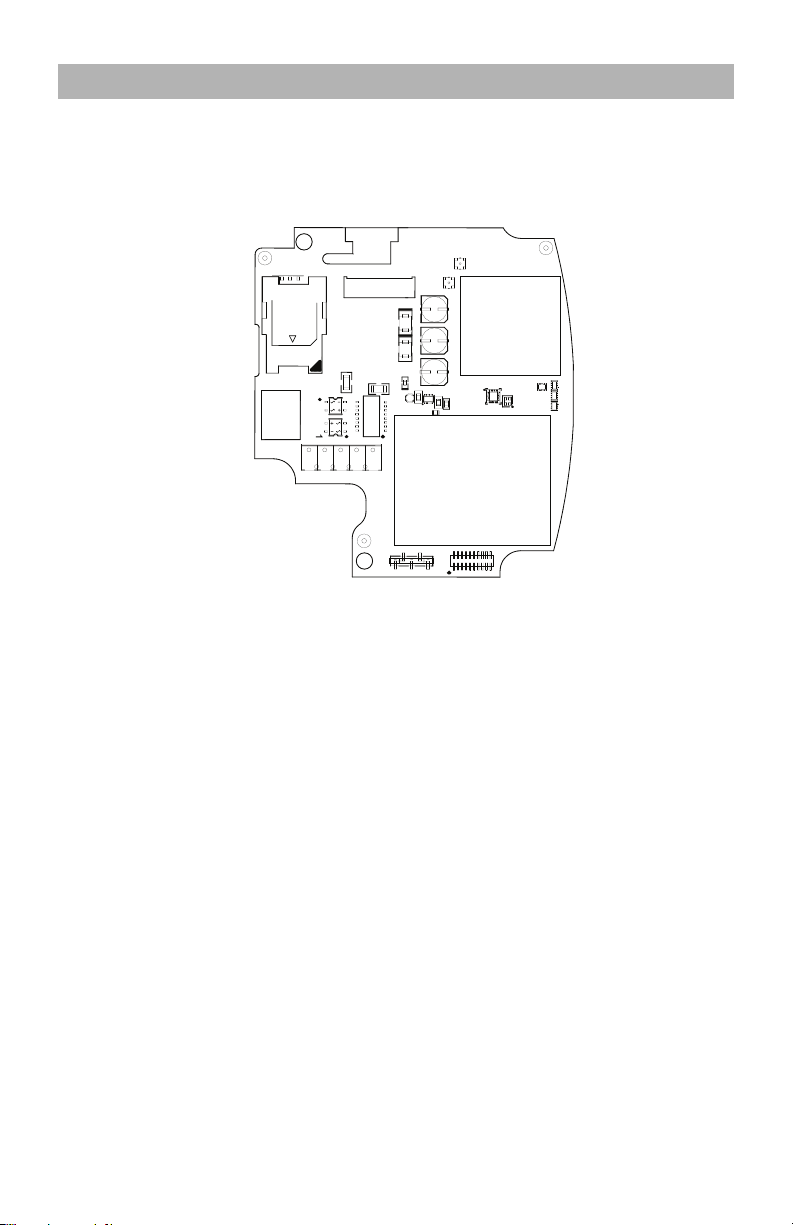
Figure 1: Communication Board Connection Points
NOTE: The Alarm Communicator is installed in the SCW prior to shipment by Digital Security
Controls (DSC). The Factory Installation includes insertion of the SIM card. The SCW should not
be mounted in its final location without performing a Communicator Test to ensure adequate
HSPA/3G coverage for the LE2077 and TL2553G Alarm Communicators
INSTALLATION LOCATION
The Communicator shall be installed in an indoor location only.
This HSPA/3G/Ethernet Communicator shall be installed by Service Persons only. (Service Person is defined as a person having appropriate technical training and experience necessary to be
aware of hazards to which that person may be exposed in performing a task and of measures to
minimize the risks to that person or other persons). The Communicator shall be installed and
used within an environment that provides the pollution degree max 2, over voltages category II,
in non-hazardous, indoor locations only. This manual shall be used with the Installation Manual
of the alarm control panel which is connected to the HSPA/3G/Ethernet Communicator. All
instructions specified within the control panel manual must be observed.
All the local rules imposed by local electrical codes shall be observed and respected during
installation.
10
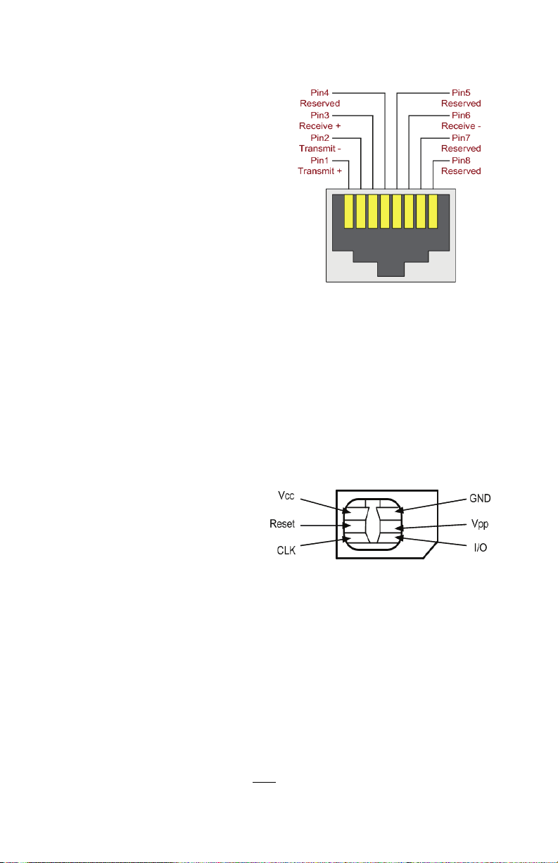
INSTALLING CAT 5 CABLE (TL2553G ONLY)
RJ-45 Connector
DG0009635
Figure 2: RJ-45 Pinout
SIM Card Pinouts
DG0009396
Figure 3: SIM Card Pinouts
A Category 5 (CAT 5) Ethernet cable must be
run from a source with Ethernet/Internet connectivity to the Communicator module, inside
the Self Contained Wireless Control Panel cabinet. The Communicator end of the cable must
have an RJ-45 plug, which connects to the
Communicator’s RJ-45 jack. All requirements
for installation of CAT5 Ethernet cable must be
observed for correct operation of the Communicator, including, but not limited to, the following:
• Do NOT strip off cable sheathing more than
required for proper termination.
• Do NOT kink/knot cable.
• Do NOT crush cable with cable ties.
• Do NOT untwist CAT5 pairs more than
1.2cm (”).
• Do NOT splice cable.
• Do NOT bend cable at right angles or make
any other sharp bends.
NOTE: CAT5 specification requires that any cable bend must have a minimum 5 cm (2 in.) bend
radius. Maximum length of CAT 5 cable is 100m (328 ft.).
NOTE: The Ethernet cable shall not be visible when the installation is complete unless the install
is a surface mount installation.
INSERTING/REMOVING
THE SIM CARD
1. Remove the front cover
of the SCW Control
Panel to access SIM
card holder.
2. Remove power from the
SCW and disconnect
the backup battery
connections.
3. On the SIM card holder push gently to slide the cover towards OPEN as indicated by the
arrow on SIM holder. This will unlatch the SIM card holder on the side furthest from edge of
the Communicator. See Figure 1.
4. Lift up the SIM card holder from the side that is not hinged.
NOTE: The SIM card can be damaged by bending or scratching contacts. Use caution when
handling the SIM card.
5. Insert or remove the SIM card, noting the orientation of the notches on the SIM card and the
SIM card holder.
6. When inserting a SIM card, insert the card in the proper orientation and gently push the SIM
7. Apply AC power to panel, and replace the panel cover.
NOTE: If two way audio is enabled you will NOT
card holder down and slide the holder as indicated by the arrow on SIM holder, to LOCK.
be able to swap the SIM card with another card.
11

COMMUNICATOR RESET
The Communicator can be reset by cycling the power on the SCW.
ESTABLISHING A COMMUNICATION CHANNEL WITH THE SCW PANEL.
The Communicator interfaces to the SCW through a keyed 16 pin Ribbon cable. See Table 6 .
The key prevents incorrect connection of the ribbon cable connector to the SCW and Communicator. The pinout for the Ribbon cable is provided in the Table below:
Table 6: Communicator Ribbon cable to SCW
Pin # Signal Pin # Signal
1PC-Link TX 2PC-Link RX
3GND 4Vref
5Vref 6GND
7 AUD-OUT_N 8 AUD-OUT_P
9 AUD-IN_P 10 AUD-IN_N
11 GND 12 SI
13 GND 14 SO
15 GND 16 Wall Tamper
Establishing a communication channel between the Communicator and the SCW is critical to
ensuring the desired operation of the two units. The following steps must be completed during
the on-site installation. Program the following to ensure that the Communicator and the panel
will work together as intended.
Initial Programming of Communicator and SCW
1. Enter
NOTE: When programming Toggle Options, the toggle is ON when the number is displayed and
OFF when the number is not dis played. (e.g., [1---5---], Toggle Options 1 and 5 are ON, all
others are OFF).
2. Panel Section [167] Cellular/Ethernet Interface Communications ‘Wait for ACK’: Default
3. When the communicator is installed with the SCW panel, 4 telephone numbers are
4. Panel Sections [301], [302], [303], and [305] can be configured as Primary
[*][8][Installer Code] [Section Number]
for panel programming. Record any values that
are modified from their default, in the appropriate Programming Worksheets.
value is: 060 seconds.
available to backup one another. You can set up these 4 telephone numbers to perform in
one of two ways: Backup dialling or Alternate dialling.
a. Backup dialling: each of the 4 telephone numbers will make 5 dialling attempts in turn,
before an FTC trouble is displayed on the keypad.
b. Alternate dialling: each telephone number makes 1 dialling attempt before moving on to
the next number, cycling through each of the 4 numbers for a total of 5 times each. If all 4
numbers fail the 5 attempts, an FTC trouble is displayed on the keypad.
communication paths.
a. Panel Sections [302], [303], and [305] may also be configured for backup or redundant
communications by using Panel Section(s) [383] or [351] - [376]. Refer to the SCW
panel Installation Manual for more information.
If a valid telephone number is programmed, communications will use Public Switched Telephone Network (PSTN). Entering a 4 digit hexadecimal value for a telephone number will
change the call routing to the Communicator, as determined by the number programmed:
DCAAF:Internal (All Receivers). Signals will be routed depending on Section [851] [006] programming.
DCBBF:Ethernet Receiver 1 (Primary). (Not available for LE2077).
DCCCF:Ethernet Receiver 2 (Backup). (Not available for LE2077).
DCDDF:Cellular Receiver 1 (Primary).
DCEEF:Cellular Receiver 2 (Backup).
12

NOTE: Add a single ‘F’ as a suffix to the 4 digit hex number to populate the unused remainder of
the 32 character field.
5. Panel Section [350]: If any of the phone numbers have been programmed as DCAA, DCBB,
DCCC, DCDD, or DCEE, panel Section [350] must be set to [04] if SIA format or [03] if
Contact ID (CID) format is used by control panel.
6. Panel Section [382]: Toggle Option [5], ‘GS/IP Module Enabled’, must be set to ON.
7. Panel Section [401]: Toggle Option [1] must be set to ON in order to perform panel DLS
session through Cellular or Ethernet data channel.
8. Panel section [310], account code, auto syncs with the communicator account code in
section [021]. The panel account code ([*][8][installer code] [310]), will overwrite the
communicator account code section ([*][8][installer code] [850] [021]) if programmed
differently.
NOTE: Keep a record of the SIM card telephone number, it is required by users for SMS
Command and Control functions. (The number can be recorded in the Programming
Worksheets Section of this document, under Option [996]). Due to the nature of the SIM card
activation process with Cellular network carriers, it can take up to 24 hours for SIM card
activation to be complete.
SMS COMMAND AND CONTROL FUNCTIONS
SMS Command and Control is available on SCW9055/57 panels. Users can send SMS text
messages from their mobile phone to the GSM phone number assigned to their system. Commands are only accepted from telephone numbers that have been programmed in Sections
[311]-[318]. The system will reject messages sent from telephone numbers that are not on the
programmed list.
When the received SMS text matches a valid Section message, the function is performed on
the control panel. Text messages are not case sensitive and extra spaces are ignored. A User
Access Code may be required for some SMS messages.
The SMS Message format is in 3 parts: Command, Partition Label (or only the partition number),
and Access Code.
If an Access Code is included in the message, it is sent to the control panel for validation, along
with the requested function.
If the panel is configured to require an Access Code and the code is not sent (or invalid) the
panel will fail the function (unsuccessful).
If the panel fails the function, an SMS response message is sent to the user. The SMS response
will echo the command sensat, followed by the label “unsuccessful”. (e.g., “night arm partition 2
1234 unsuccessful”).
The partition label or partition number may be excluded from the SMS request in a single partition system (e.g., disarm 9123).
NOTE: The GSM phone number can be viewed in Section [851] [996], and/or [851] [229] or
by entering *6, then scrolling down to “SMS Programming” and scrolling down to “Cellular
phone No”.
LABEL PROGRAMMING for SMS MESSAGE
Programmable Labels can not be modified in Connect24, use DLS IV for label programming
only, if labels need to be modified. Before initiating remote programming, record your network’s
Public IP Address and port for incoming DLS IV connections.
1. Run the DLS IV software on your computer. DLS IV will connect to the unit, using the Public IP
address, and make an Ethernet connection. If the Ethernet connection fails, DLS IV will report
an error and prompt you to connect using Cellular.
13

NOTE: If required, download the DLS IV software from DSC: http://www.dsc.com. If you select
Cellular connection, DLS will request Connect24 to send an outgoing SMS message to the
unit.
2. Connect24 will confirm that the account has DLS service and will provide the Public IP
address and port number of the DLS server in an SMS message.
3. SMS message will establish a connection to your computer’s DLS IV software (to change
programming labels only).
4. Create an account for the panel/Communicator, select the Communicator type (e.g., SMS -
TL2553G) and enter all relevant information in SMS section.
NOTE: The Cellular telephone number will also be required by the user, to send SMS Command
and Control messages to their system.
5. Program the account information, then click Global Download and choose SMS as the
Connection Type. Click OK.
6. The download path configured in Programming Section [005] Toggle Option[4]
determines the Cellular or Ethernet path to be used.
COMMUNICATOR PLACEMENT TEST
(LE2077/TL2553G only)
1. Using the keypad enter the installer mode:
2. View and record the number of bars showing on the SCW LCD.
3. Compare with the number of bars indicated in the “CSQ Levels” column shown in Table 7 .
4. If 3 or more bars are shown, the location is GOOD and no further action is required.
5. If the location is BAD, move the SCW to various suitable locations until 3 or more bars are
obtained.
Table 7: Communicator CSQ Levels
Signal
Strength
No Signal 0 -108.8 Check if Cellul ar coverage is active in your area.
1 Bar 1 to 4 -108d to -103
2 Bars 5 to 6 -102 to -99
3 Bars 7 to 10 -98d to -91
5 Bars 14 and higher -84 and higher
CSQ Level
Signal Level
dBm
Location is BAD. Not suitable for Cellular operation.
Location is GOOD.4 Bars 11 to 13 -90 to -85
NOTE: The communicator is capable of indicating signal strength even without an active SIM,
but signal indication may take up to 1-2 minutes.
[*][8]
[installer code] [850].
Installer Action
GENERAL INFORMATION
i Domain Name Service (DNS) programming is not permitted in UL/ULC listed systems.
KEYPAD DATA DISPLAY
• Section-Toggle Options: The number is displayed when Toggle is ON. The number is not
displayed when Toggle is OFF. (e.g., Toggle Options displays: “[--3--6--]”. Options 3 and 6
are ON, all others are OFF). Pressing keys 1 through 8 will alternately turn the Toggle ON and
OFF.
• HEX/Decimal Data: Values that are provided with two defaults, separated by a / character,
use the format: hexadecimal followed by decimal equivalent (e.g., Default [0BF5/3061]).
Hexadecimal numbers are shown, with all leading zeroes, to the full field length defined for
the number.
ENTERING DATA FROM KEYPAD
To enter data at the keypad, press the number key, from the table below, to select the character
that you want. Pressing the number key repeatedly will scroll through the characters available
14

for that key. Press the [*] key and use
[<] [>] keys to scroll to one of the following selections: (Press
[*] to select the Option.)
• ASCII Entry. Use this mode to enter ASCII characters from the keypad.
• Clear to End. This selection will clear the remainder of the display.
• Clear Display.This selection will completely erase all entries on the display.
• Change Case. Toggles between upper/lower case depending on current selection.
NOTE: The “0” on the keypad is used to delete characters.
Table 8: Data Entry at Keypad
Key Value
1 1-A-B-C 4 4-J-K-L 7 7-S-T-U
2 2-D-E-F 5 5-M-N-O 8 8-V-W-X
3 3-G-H-I 6 6-P-Q-R 9 9-Y-Z-0
Ke
ValueKeyValue
y
ENTERING ASCII CHARACTERS
To enter American Standard Code for Information Interchange (ASCII) characters at the keypad,
perform the following:
1. Press [*] and use [<] [>] keys to scroll to “ASCII Entry”.
2. Press [*] to select ASCII entry mode.
3. Use the
4. Press [*] to exit ASCII character entry mode and return to normal entry.
NOTE: Authorized access to Connect24 (LE2077/TL2553G) is required to modify any
Ethernet/Cellular Programming Section. Specific panel sections must be configured for proper
operation of the Communicator with the panel.
[<] [>] keys to scroll to display the ASCII character you want to use and press [*] to
accept.
15

ETHERNET/CELLULAR PROGRAMMING OPTIONS
The Programming Sections described in this document can be viewed at the SCW LCD. To start
programming enter: [*][8][installer code] [851][# # # ], Where # # # is the 3 digit Section
number referenced in this section. The Programming Worksheets at the end of this document
can be used to record the new values when programming changes have been made from the
default values.
Programming Sections are accessed through Connect24. Installers may review/record programming Options at the panel.
NOTE: Ethernet/Cellular Programming Sections accessed through the panel are for display
purposes only. Configuration changes must be done using Connect24.
SYSTEM OPTIONS
[001] Ethernet IP Address
Default (000.000.000.000)
Enter the IP address of the Communicator. Ensure that the IP address is unique to your Communicator on the local network. Format is 4 fields, each field is a 3 digit decimal number. Valid
range: 000-255. If an IP address is programmed in this Section, the unit will operate with Static
IP (DHCP disabled). Sections [002] and [003] must also be programmed when using Static IP
addresses.
NOTE: Default for this Section is Dynamic Host Configuration Protocol (DHCP) enabled. When
[002] Ethernet IP Subnet Mask
Default (255.255.255.000)
Enter the Ethernet IP Subnet Mask of the Communicator. Format is 4 fields, each field is 3 digits.
Valid range: 000-255.
NOTE: If DHCP is enabled, the DHCP Server will assign the subnet mask for this Section and the
programmed value will be ignored.
[003] Ethernet Gateway IP Address
Default (000.000.000.000)
Enter the Ethernet Gateway IP address of the Communicator. The gateway IP address is
required when a router is used on the local network to reach the destination IP address
specified in Section [001]. Format is 4 fields, each field is a 3 digit decimal number. Valid range:
000-255.
NOTE: If DHCP is enabled, the DHCP Server will assign the Gateway IP address for this Section
[004] Receiver Supervision Interval
Default (0087/135)
When receiver supervision is enabled (ON) in Section [005] Toggle Option [3], the unit sends
heartbeats to Ethernet Receiver 1 or Cellular Receiver 1 to test the communications path. Use
this Section to set the interval time (in seconds) when heartbeats will be sent to the receivers.
Valid range 000A-FFFF seconds. If the programmed value is less than (000A/10) seconds,
supervision is disabled.
• Receiver Window: This is the supervision timeout that must be configured at the central
• Recommended Values: This is the recommended heartbeat interval that should be
• For ULC installations, the Daily test transmission must be enabled over each available
enabled, the DHCP Server will set values for: IP Address [001], Subnet Mask [002],
and Gateway [003]. Programming an IP address in this Section will disable DHCP
(Static IP).
and the programmed value will be ignored.
station receiver.
programmed into the Communicator.
communication channel Sections [125] and [225]. When programming with Connect24,
the recommended intervals will be programmed automatically when the required window is
selected.
16
 Loading...