

Tyco Safety Canada 17TL280LER Users manual

TL280LE(R)
Internet and LTE/HSPA Dual-Path Alarm
Communicator
LE2080(R)
LTE/HSPA Alarm Communicator
3G2080(R)E
Cellular Alarm Communicator
TL2803G(R)E
Internet and HSPA Dual-Path Alarm Communicator
TL280(R)E
Internet Alarm Communicator
Installation Manual v5.1
WARNING: This manual contains information on limitations regarding product use and
function and information on the limitations as to the liability of the manufacturer. The
entire manual should be carefully read.
PLEASE NOTE THAT NOT ALL MODELS AND FEATURES LISTED ARE AVAILABLE IN
ALL MARKET S.

Table of Contents
Table of Contents 2
WARNING: Installer please read carefully 4
General 5
IMPORTANT 5
Safety Information 5
Model Info rmation 5
Panel Mou nting 6
Features 6
Technical Specifications 6
Ratin gs Co mpatib ility 7
Pre Installation Configuration 7
Encryption 7
Communicator Installation Configuratio n 8
Installing the Ethernet Cable (TLXXXX ModelsOnly) 8
Inserting and Removingthe SIM Card 8
Running the RS-232 Cable (R modelsonly) 8
Installing Communicat or in Panel 8
Installing Communicator with HS2016, HS2032, HS2064, and HS2128 Panel 8
Communicator Placement Test 12
Cellular Communicators ModelsOnly 12
Cellular Signal Strength Display- LCD Keypad only 12
Initial Panel Programming 13
Keypad Data Display 13
Entering HEX values at keypad 13
Entering ASCII Characters at keypad 13
HS2016/2032/2064/2128 Initial Programming 13
Activating the Communicator with C24 Communications 13
SMS Command and Control 13
SMS Commands 14
Communicator Status LEDs 14
Yellow Trouble LED 14
Panel Supervision T rouble (2 Flashes) 14
SIM Lock Trouble (4 Flashes) 15
Cellular T rouble (5 Flashes) 15
Ethernet Trouble (6 Flashes) 15
Receiver Not Available (7 Flashes) 15
Receiver Supervision Trouble (8 Flashes) 15
FTC Trouble (9 Flashes) 15
Module Configuration Trouble (12 Flashes) 15
Red Network Connection Status LED 15
(Green LED 1) (Green LED 2) and (Yellow LED) Signal Strength 15
Network ActivityLEDs - Red and Green(TL2803G(R)E / TL280LE(R) only) 16
Communicator Troubleshooting 16
Ethernet/Cellular Programming Options 18
System Options 18
Programming Options 20
Communications Reporting Codes 23
2

System Test Options 23
Ethernet Receiver 1 Options 25
Ethernet Receiver 2 Options 25
Ethernet Options 26
Cellular Receiver 1 Options 27
Cellular Receiver 2 Options 27
Cellular Options 28
SMS Event Notification/Command and Control Options 29
External Event Label Programming 35
Receiver DiagnosticTesting 38
System Information (Read Only) 38
System Reset Defaults 42
Ethernet Cellu lar Programming Worksheets 43
System Options 43
Programming Options 43
System Test Options 44
Ethernet Receiver 1 Options 44
Ethernet Receiver 2 Options 44
Ethernet Options 44
Cellular Receiver 1 Options 44
Cellular Receiver 2 Options 45
Cellular Options 45
Command and Control Options 45
External Event Label Programming 50
Receiver DiagnosticTesting 54
System Information (Read Only) 55
System Reset Defaults 55
Limited Warranty 56
EULA 56
Regu latory Information 57
3

WARNING: Installer please read
carefully
Note to Installers
The warnings on this page contain vital information. As the only individual in contact withsystem users, it is the installer’s responsibility to
bring each item in this warning to the attention of all users of this system.
System Failures
This system has been carefully designed to be as effective as possible.
There are circumstances, however, involving fire, burglary, or other
types of emergencies where it may not provide protection. Any alarm
system of any type may be compromised deliberately or may fail to
operateas expected for a variety of reasons. Some, but not all, of the
reasons may be:
Acc ess by Intruders
Intruders may enter throughan unprotected access point, circumvent a
sensing device, evade detection by moving through an area of insufficient coverage,disconnect a warning device,or interfere with or prevent the proper operation of the system.
Component Failure
Although every effort has been madeto make this system as reliable
as possible, the system may fail to function as intended due tothe failure of acomponent.
Comprom ise of Radio Fre quency (Wir eless) D evice s
Signals may not reach the receiver under all circumstances which
could include metal objects placed on or near the radio path or deliberatej amming or other inadvertent radio signal interference.
Criminal Knowledge
This system contains security features which were known to be effective at the time of manufacture. It is possible for persons with criminal
intent to developtechniques which reducetheeffectiveness of these features. It is important that the security system be reviewed periodically
to ensure that its features remain effective and that it is updated or
replaced if it is foundthat it does not providethe protection expected.
Failure of Re placeable Batte ries
This system’s wireless transmitters have been designed to provide
several years of battery life under normal conditions. The expected battery life is a function of the deviceenvironment, usage, andtype. Ambient conditions such as high humidity, high or low temperatures, or
large temperature fluctuations may reduce the expected battery life.
While each transmittingdevice has a low battery monitor w hich identifies when the batteries need to be replaced, this monitor may fail to
operate as expected. R egular testing and maintenance will keep the
system in good operating condition.
Inadequate Installation
A security system must be installed properly in order to provide
adequate protection. Every installationshould be evaluated by a security professional to ensure that all access points andareas are covered.
Locks and latches on windows and doors must be secure and operate
as intended. Windows, doors, walls, ceilings and other building materials must be of sufficient strength andconstruction to provide the level
of protection expected. A reevaluation m ust be done during and after
any construction activity. An evaluation by the fire and/or police department is highly recommendedi f this service is available.
Inadequate Testing
Most problems that would prevent an alarm system from operating as
intended can be found by regular testing and maintenance. The completesystem should be tested weekly andimmediately after a break-in,
an attempted break-in, a fire, a storm, an earthquake, an accident, or
any ki nd of construction activity inside or outside the premises. T he
testing should include all sensing devices, keypads, consoles, alarm
indicating devices, and any other operational devices that are part of the
system.
Insufficie nt Time
There may be cir cumstances when thesystem will operate as intended, yet the occupants will not be protected from an emergency due to
their inability to respond to the warnings in a timely manner. Ifthe system is remotely monitored, the response may not occur in time to protect the occupants or their belongings.
Motion Det ec tors
Motion detectors canonly detect motionw ithin thedesignatedareas as
shown in their respective installation i nstructions. They cannot discriminate between intruders and intendedoccupants. Motion detectors
do notprovidevolumetric area protection. They havem ultiple beams of
detection and motion can only be detected i n unobstructed areas
covered by these beams. They cannot detect motion w hich occurs
behindwalls, ceilings, floor, closed doors, glass partitions, glass doors
or windows. Any type of tamperingw hether intentional or unintentional
such as masking, painting, or spraying of any material on the lenses,
mirrors, windows or any other part of the detection system will impair
its proper operation.
Passive infraredm otion detectors operate by sensing changes in temperature.However their effectiveness can be reducedwhen the ambient temperature rises near or above body temperature or if there are
intentional or unintentional sources of heatin or near the detection area.
Some of these heat sources could be heaters, radiators, stoves, barbecues,fireplaces, sunlight, steam vents, lighting andso on.
Power Failure
Control units, intrusion detectors, smoke detectors and many other
security devices require an adequate power supply for proper operation. If a device operates from batteries, it is possible for the batteries
to fail. Even if the batteries have not failed, they must be charged, in
good condition and installed correctly. If a device operates only by AC
power, any interruption, however brief, will r ender that device inoperative while it does not have power. Power interruptions of any length
are often accompanied by voltagefluctuations which may damage electronic equipment such as a security system. After a power interruption
has occurred, imm ediately conduct a complete system test to ensure
that the system operates as intended.
Security and Insurance
Regardless of its capabilities, an alarm system i s not a substitute for
property or life insurance. An alarm system also is not a substitute for
property owners, renters, or other occupants to act prudently to prevent
or minimize theharmful effects of an emergency situation.
Smoke D et ect ors
Smoke detectors that are a part of this system m ay not properly alert
occupants of afir e for a number of reasons, some of which follow. The
smoke detectors m ay have been i mproperly installed or positioned.
Smoke may not be able to reach the smoke detectors, such as when
thefire is in a chimney, walls or roofs, or onthe other side of closed
doors. Smoke detectors may not detect smoke from fires on another
level of the residence or building.
Every fire is different in the amount of smoke produced and the rate of
burning. Smoke detectors cannot sense all types of fires equally well.
Smoke detectors may not provide timely warning of fires caused by
carelessness or safety hazards such as smoking in bed, violent explosions, escaping gas, improper storage of flammable materials, overloadedelectrical circuits, childrenplaying withmatches, or arson.
Even if the smoke detector operates as intended, there may be ci rcumstances when there is insufficient warning to allow all occupants to
escape in time toavoid injury or death.
Telephone Lines
If telephonelines are used to transmit alarms, they m ay be out of service or busy for certain periods of time. Also an intruder may cut the
telephone line or defeat its operation by more sophisticated means
which may be difficult to detect.
Warning De vices
Warning devices suchas sirens, bells, horns, or strobes may not warn
people or waken someone sleeping if there is an intervening wall or
door. If warning devices are located on a different level of the residence
or premise, then it i s l ess likely that the occupants wil l be alerted or
awakened. Audible warning devices may be i nterfered with by other
noise sources such as stereos, radios, televisions, air conditioners,
other appliances, or passing traffic. Audible warning devices, however
loud, may not be heard by a hearing-impaired person.
4
General
IMPORTANT
This installation manual shall be used inconjunction with the control panel. All the safety instructions specified within that manual shallbe observed. The control panel is referenced asthe “panel” throughout this
document. This installation guide provides the basic wiring, programming and troubleshooting information.
The HSPA(3G)/dual-path alarm communicator isa fixed, wall-mounted unit, and shall be installed in the
location specified in these instructions.The equipment enclosure must be fully assembled and closed,
with all the necessary screws/tabs, and secured to a wall before operation. Internal wiring must be
routed in a manner that prevents:
l Excessive strain on wire and on terminal connections,
l Interference between power limited and nonpower limited wiring,
l Loosening of terminal connections, or
l Damage of conductor insulation.
WARNING: Never install this equipment during a ligh tning storm!
Safety Information
The installer must instruct the system user on each of the following:
l Do not attempt to servicethis product. Opening or removing covers may expose the user to dan-
gerous voltages or other risks.
l Any servicing shall be referred to service per sons only.
l Use authorized accessories onlywith this equipment.
l Do not stay close to the equipment during device operation.
l Do not touch the external antenna.
Model Information
This manual covers the following modelsof alarm communicators:
Models TL2803GRE, T L2803GE, 3G2080RE, 3G2080E, TL280RE and TL280E are for North America and cover the following bands:850 / 1900MHz.
Models TL2803GRE- EU , TL2803GE- EU, 3G2080RE- EU and 3G2080E- EU are for Europe/International and cover the following bands: 900/1800 MHz.
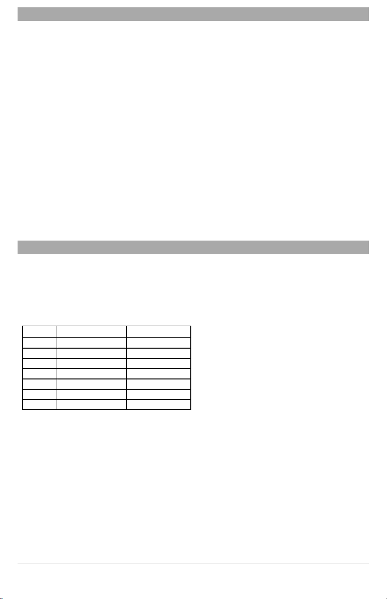
Models TL280L ER , TL280LE, LE2080R , LE2080 are for North America and support LTE bands B2,
B4, B5, B12 and B13 and WCDMA bandsB2 and B5.
Band Transmit Band (Tx) Receive Band (Rx)
LTE B2 1850 - 1910 MHz 1930 - 1990 MHz
LTE B4 1710 - 1755 MHz 2110 - 2155 MHz
LTE B5 824 - 849 MHz 869 - 894 MHz
LTE B12 698 - 716 MHz 728 - 746 MHz
LTE B13 777 - 787 MHz 746 - 756 MHz
UMTS B2 1850 - 1910 MHz 1930 -1990 MHz
UMTS B5 824 - 840MHz 869 - 894MHz
References to model names TL280(R)E, TL2803G(R)E, 3G2080(R)E , TL280LE(R) and LE2080(R)
throughout this manual apply to all specified models unless stated differently. Models ending in “R”
include abuilt-in RS-232 interface for connecting to localthird party applications.
The TL280( R) E/TL2803G(R)E/3G2080(R) E/TL280LE(R) /LE2080(R supports integration over cellular/IP, available with licensed 3rd party product solutions. Specific programming for the related programming sections is to be provided by the 3rd party. A current list of compatible 3rd party solutions can
be found at www.dsc.com.
3G2080(R)E: Is a HSPA(3G) cellular alarm communicator that sends alarm communication to Sur- Gard
System I-IP, II, III (SG-DRL3IP), IV (SG-DRL4IP), and 5 (SG- DRL5IP) central station receivers via a
HSPA(3G)/GPRS digital cellular network. TL2803G(R)E: Isa dual-path HSPA(3G) Ethernet alarm communicator that sends alarm communication to Sur- Gard System - IPI, II, III, IV, and 5 central station
receivers through Ethernet/Internet or a HSPA(3G)/GPRS digital cellular network.
TL280(R)E: Isan Ethernet alarm communicator that sends alarm communication to Sur-Gard System IIP, II, III (SG-DRL3IP), IV (SG- DRL4IP), and 5 (SG- DRL5IP) central station receivers via Ethernet/Internet.
5

LE2080(R) : is an LTE (4G) cellular alarm communicator with HSPA(3G) fallback support that sends
alarm communications to Sur- Gard System I- IP, II, III (SG- DRL2IP, IV (SG-DRL4IP) and 5 (SGDRL5IP) central station receivers via an LTE(4)/HSPA(3G) digitalcellular network.
TL280LER: Is a dual path LTE (4G) Ethernet alarm communicator that sends alarm communications to
Sur-Gard System I-IP, II, III(SG-DRL3IP, IV (SG-DRL4IP) and 5 (SG-DRL5IP) central station receivers
via Ethernet/Internet or a LTE(4)/HSPA(3G) digital cellular network.
The communicator can be used as either a backup or primary communicator. The communicator supports Internet Protocol (IP) transmission of panel and communicator events over Ethernet/Internet
and/or HSPA/GPRS.
The cellular performance of the LE2080 ( R), TL280LE (R), 3G2080( R) E or TL2803G (R) E communicators depend greatlyon the LTE(4G)/HSPA(3G) network coverage in the localarea.
Optionalantenna kits (GS-15ANTQ, GS-25ANTQ, GS-50ANTQ) are available from DSC to improve signal strength asrequired.
NOTE: Prior to installation, confirm with the local serviceprovider that the LTE(4G)/HSPA(3G) network
isavailable and active in the area where the communicator will be installed, and that radio signal
strength (CSQ) is adequate.
Panel Mounting
The following communicators are compatible with HS2016, HS2016-4, HS2032, HS2064, and HS2128
panels:
l 3G2080(R)E (HSPA(3G)/GPRS only)
l TL2803G(R)E (Ethernet/Internet + HSPA(3G)/GPRS dual-path)
l TL280(R)E (Ethernet/Internet only)
l LE2080(R) (LTE(4)/HSPA(3G) only)
l TL280LE(R) (Ether net/Internet +LTE(4)/HSPA(3G))
Features
l 128-bit AESencryption viacellular and Ethernet/Internet (NIST validationcert. number 2645).
l Backup or primary cellular alarm communication.
l Automatically switches to 2G (EDGE/GPRS) if HSPA(3G) service is not available.
l Ethernet LAN/WAN 10/100 BASE-T (TL2803G(R)E and TL280(R)E only).
l Fully redundant Ethernet/Internet and cellular dual-path alarm communication (TL2803G(R)E only).
l Full event reporting to central station.
l IndividualInternet and/or cellular per iodic test transmission.
l Integrated callrouting.
l VisualVerification (Requires Sur-Gard System 5 Receiver)
l Remote firmware upgrade capabilityof the communicator and panel firmware via Ethernet and/or cel-
lular.
l Panel remote uploading/downloading support viacellular and Ethernet/Internet.
l PC-LINK connection.
l Programmable labels.
l SIA and Contact ID (CID) formats supported.
l Signal strength and trouble displayLEDs.
l Supervisionheartbeats sent via cellular and Ethernet/Internet.
l Third party integration over cellular/IP. The product supports third party applicationvia serial (R-mod-
els only), cellular and, Ethernet. Refer to third-party application documentation for more information.
Technical Specifications
The TL2803G(R) E is also suitable to be used with a compatible control unit listed for dual line security
transmission when used in conjunction with a DACT or a Public Switched Data Network (PSDN) transmitter, where the PSDN provides the line security and is the primary line. In this mode, alarm signals are
to besent simultaneously over both communicationmethods.
6
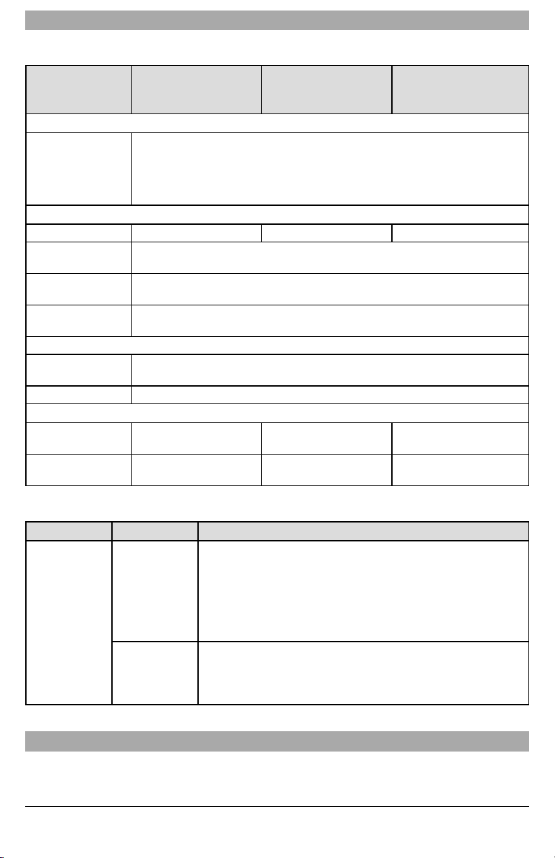
Ratings Compatibility
Table 1: Communicator Ratings
Model
3G2080(R)E /LE2080
(R)
Cellular only
TL280(R)E
Internet only
Power Supply Ratings
10.8-12.5 VDC
Power is supplied from th e pan el’s PC-Link header or PCL-422 module in remote
Input Voltage
cabinet installations. In remote cabinet installations, the PCL-422 module located
with the communicator is powered by an HSM2204 or an HSM2300. Refer to the
PCL-422 installation sheet for details.
Current Consumption
Standb y Current 90mA @ 13.66V 120 mA @ 13 .66V
Alarm (Transmitting)
Current
Operating
Frequency
Typical Antenna
Gain
400 mA @ 12 V
850 MHz, 1900MHz
2dBi
Environmental Specifications
Operating
Temperature
-10°C to 55°C
Humidity 5% ~ 93% relative humidity, non-conde nsing
Mechan ical Specificatio ns
Board Dimensions
(mm)
Weight (grams) with
bracket
100 × 150 × 15 100 × 150 × 15
310 320
TL2803G(R)E/TL280LE
(R)
Internet and Cellular
Table 2: Compatible Receivers and Panels
Communicator Receiver/Panel Description
l Sur-Gard System I-IP Receiver, version 1.13+
l Sur-Gard System II Receiver, version 2.10+
l Sur-Gard SG-DRL3-IP, version 2.30+ (for Sur-Gard System III
3G2080(R)E
LE2080(R)
TL2803G(R)E
TL280LE(R)
TL280(R)E
Receiver
Panel
Receiver)
l Sur-Gard SG-DRL4-IP version 1.20+ (for Sur-Gard System IV
Receiver)
l Sur-Gard SG-DRL5-IP version 1.00+ (for Sur-Gard System 5
Receiver)
l HS2016
l HS2016-4
l HS2032
l HS2064
l HS2128
NOTE: Enter [*][8][Installer Code][900] at keypad to view the panel version number.
Pre Installation Configuration
Encryption
The communicator uses128 Bit AES encryption. Encryption can onlybe enabled from themonitoring station receiver. Each receiver (Ethernet 1 and 2, cellular 1 and 2) can independently have encryption
7

enabled or disabled. When encryption is enabled,the central station will configure the device to encrypt
communicationsthe next time the communicator module performs a communicationto that receiver.
NOTE: Packets will start being encrypted only after the next event is sent to that receiver, or if the unit is
restarted.
Befo re leaving the inst allation site, t he communicator TL2803G (R)E Ethernet line shall be
connected via an APPROVED (acceptable to the local authorities) Network In terface Device
(NID). All wiring shall be perfo rmed according to the local electrical codes.
Communicator Installation Configuration
This HSPA(3G)/dual-path alarm communicator shall be installed by servicepersons only(service person
isdefined asa person having the appropriate technicaltraining and experience necessary to be aware of
hazards to which that person may be exposed toin performing a task and can also take measures to minimize the risks to that person or other persons). The Communicator shall be installed and used within an
environment that provides the pollution degree max 2, overvoltages category II, in non- hazardous,
indoor locations only. This manual shall be used with the installation manual of the panel which is connected to thecommunicator. All instructions specified within the panel manual must be observed.
Allthe local rules imposed by local electrical codes shallbe observed and respected during installation.
Installing the Ethernet Cable (TLXXXX Models Only)
A Category 5 (CAT 5) Ethernet cable must be run from a source with Internet connectivity to the communicator module, inside the panel. T he communicator end of the cable must be terminated with an
RJ45 plug, which will connect to the communicator’s RJ45 jack after the communicator is installed. All
requirements for installation of CAT5 Ethernet cable must be observed for correct operation of the communicator, including, but not limited to, the following:
l Do NOT strip off cable sheathing more than required for proper termination.
l Do NOT kink/knot cable.
l Do NOT crush cable with cable ties.
l Do NOT untwist CAT5 pairs more than ½ in. (1.2cm).
l Do NOT splice cable.
l Do NOT bend cable at right angles or make anyother sharp bends.
NOTE: CAT5 specification requires that any cable bend must have a minimum 2 in. (5 cm) bend radius.
Maximum length of CAT 5 cable is 328 ft. (100 m).
Inserting and Removing the SIM Card
1. Remove the front cover ofthe panel to accessSIM holder.
2. Remove power from thepanel and disconnect the battery and telephone line.
3. On the SIM card holder push gently to slide thecover downwards to OPEN. Thiswill unlatch the SIM
card holder on the top edge of the communicator PCB. (See Figure 3).
4. Tilt the top of the SIM card holder downwards to accessthe SIM card.
NOTE: The SIM can be damaged by bending or scratching contacts. Use caution when handling SIM
cards.
5. Insert or remove the SIM card, noting the orientation of the notches on the SIM card and the SIM
card holder.
6. When inserting a SIM card, insert the card in the proper orientation and gentlypush the SIM card
holder down and slide the holder asindicated by the arrow on SIM holder, to LOCK.
7. Reconnect thebackup battery and telephone line, apply AC power to panel, and replace the panel
cover.
Running the RS-232 Cable (R models only)
When installing the communicator for use with 3rd party applications an RS- 232 cable must be connected between the 3rd party device and the communicator module.
NOTE: Maximum cable length for RS-232 cable is 8 ft. (2.4 m).
Please refer to the installation manual for the 3rd party devicefor wiring instructions.
Installing Communicator in Panel
Installing Communicator with HS2016, HS2032, HS2064, and HS2128 Panel
NOTE: Before installing communicator or inserting/removing SIM, ensure that system power isOFF and
telephone line is disconnected.
1. To assemble supplied mountingbracket, perform the following: (See Figure 1).
a. Remove the 4 white plastic standoffs from the bag provided with the communicator kit.
b. Insert the 4 standoffs through the back of themounting bracket, into the holes ateach corner.
(The antenna mounting tab should be facing awayfrom you).
8
c. Place the bracket ona flat, solid surface. Holdthe communicator component side up and orient
10
4
1
2
8
3
7
6
5
11
9
9
8
the 4holes on the communicator with the4 standoffs protruding from the bracket. Push the communicator firmly and evenlyonto the standoffs until it is securely attached to the mounting
bracket.
d. Remove the panel front cover.
e. Remove and discard the circular knockout located in the top-right section of thepanel. (This hole
willbe used for connection ofthe supplied radio antenna).
f. Connect the supplied 5” (12.7 cm) antenna cable to the radio, by passing the connector through
the hole on back of the mounting bracket to the communicator board. Push the antenna con-
nector firmly into the socket on the cellular radio. ( See Figure 3).
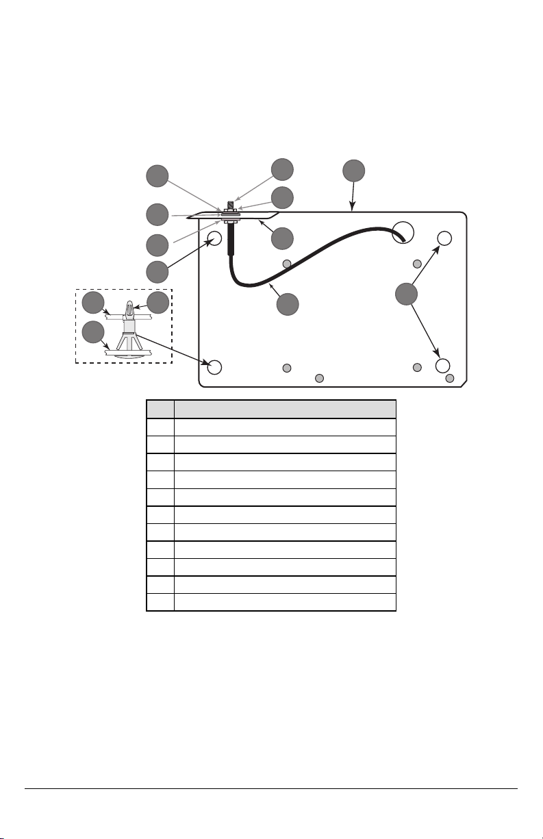
Figure 1: Communicator Mounting Bracket
Item Description
1 External Antenna Screw Thread
2 Brass Nut
3 Brass Washer
4 Nylon Washer (flat)
5 Antenn a Mounting Tab
6 Nylon Washer with bushing (thicker flat washer)
7 Antenn a Cable
8 Mounting Holes
9 Mounting Plate
10 Communicator Board
11 Stan d Off
2. Installthe Communicator into the panel:
a. Attach one end of the PC-LINK cable to the panel PCLINK_2 header on the panel(red wire
goes on the right-hand pin of the panel PCLINK_2 header (see Figure 3)).
b. Insert the assembled communicator into the panel.
NOTE: Ensure that the threaded antenna connection point isvisible through the knockout hole
c. Place the nylon washer withbushing (thick flat washer) onto the threaded section of the antenna
d. Place the second nylon washer (flat), followed by the brass washer and the brass nut, onto the
e. Locate the screw hole on the right side wall of the panel. See F igu re 2 "screw". Line up the
at the top right of the panel.
cable. Insert the threaded section through the antenna mounting knockout hole at top right of
panel.
threaded section of the cable, o ut side the panel. Tighten the assembly by hand only (finger
tight only- do not over tighten the antenna assembly).
assembled communicator with the right side wall of the panel and, using the screw provided,
9
secure the mounting bracket to the panel.
HS2016/2032/2064/2128
1 2
3
f. Attach the other end of the PC-LINK cable to the communicator (red wire goes on the right-
hand pin of the communicator PC-LINK header (See Figure 3)).
g. Using light pressure (finger tight only), attachthe supplied white quad band whip antenna to the
threaded antenna connection point at top of the panel.
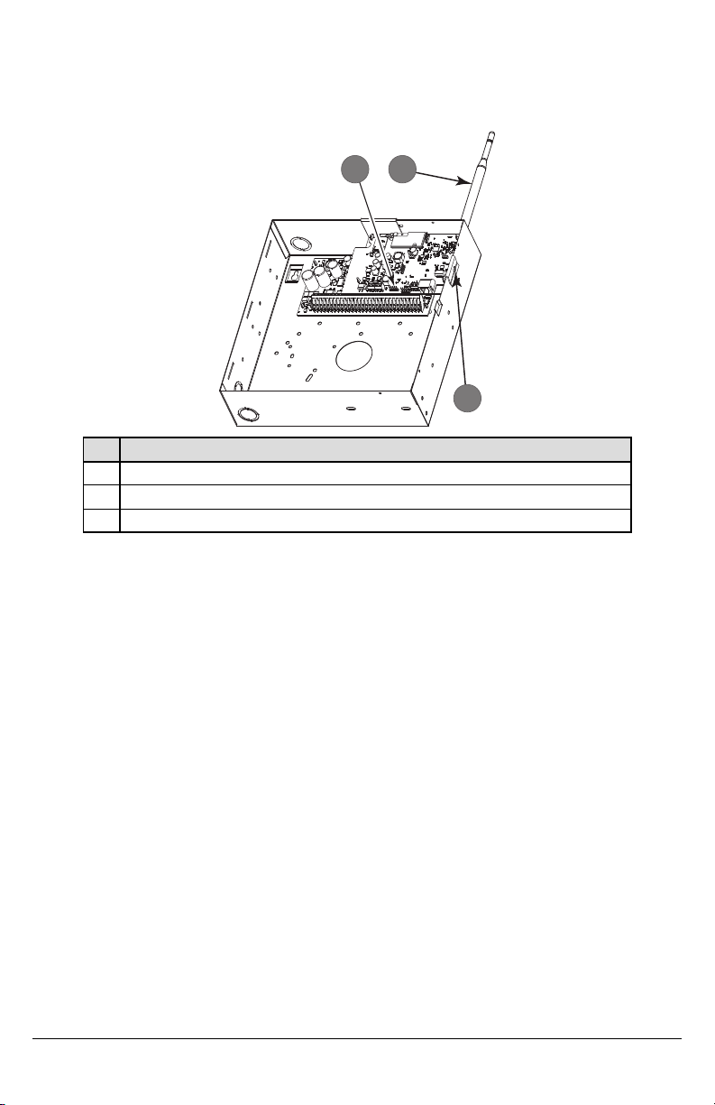
Figure 2: HS2016/2032/2064/2128 Control Panel
Item Description
1 PC-Link Cable Connector
2
Quad Band Whip Antenna - Use light pressure to attach antenna finger t igh t only
3 Screw
WARNING! - 3G2080(R) E/TL2803G(R) E/LE2080 (R)/TL280LE (R) modules are p ower limited.
Do no t route any wiring o ver t he circuit board. Maintain at least 1in. (25.4mm) separatio n
between circuit board and wiring. A minimum of ¼ in. (7mm) separatio n must be maint ained
at all points between non-power limited wiring and p ower limited wiring.
3. To electricallyconnect the communicator to the panel, perform the following steps (See Figure 3).
a. Disconnect both AC power and battery connections from thepanel, and disconnect telephone
line.
b. Confirm that the SIMcard isinserted in the holder and locked.
4. InstallNetwork Cable(TLXXXX models only). Route the CAT 5 Ethernet cablethrough back of the
panel and plug it into the communicator’s RJ45 jack.
NOTE: Before leaving the premises the Ethernet communication lines must first be connected to an
approved (acceptable to local authorities) type NID. All wiring shall be performed according to the
localelectricalcodes.
10
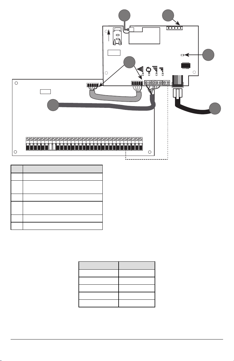
Figure 3: Communicator Wiring Diagram
AUDIO/DEFAULT
DSC
UA685
PC-LINK
PCLINK_2
COM
TL2803G(R)E
3G2080(R)E
TL280(R)E
TL280LE(R)
LE2080(R)
AC
AC
Z1 COM Z2 Z3 COM Z4 Z5 COM Z6 Z7 COM Z8
AUX+
BELL +
PGM1 PGM3
RING
T-1
HS2016/2032/2064/2128
3G/LTE Radio
UA621
L
o
c
k
1
RJ-45
GRN
YEL
TIP
R-1
BLK
RED
AUX -
BELL -
EGND
TX+
GND
TX-
RX+
RX-
SHLD
SIM
PGM2 PGM4
4
1 2
3
5
6
Item Description
1 To External Antenna
AUDIO/DEFAULT
2
Jumper pins 4 and 5 to reset
3 Network Link -Yellow
From NID use only CAT5 supervised
4
maximum cable length 100 m (328 feet)
5 RS-232 to third party device
6 RED Wire
5. Installthe RS-232 connections (R models only). If using the communicator with a 3rd party device,
wire the connections as per thetable below:
Table 3: RS-232 Connections
3rd Party Device Communicator
TX RX+
Unused RX-
RX TX+
Input Ratings:
l +10.8V ~ +12.5VDC
l 90mA(3G2080(R)E)/120mA(T L2803G(R)E) standby;
l 90mA (3G2080(R)E/ LE2080(R)
l 120mA (TL2803G(R)E/TL280LE(R).
l 400mA alarm
DSC Panel minimum power requirements:
l 16.5 VAC 40 VA transformer
l 12 VDC 7Ah battery
Unused TX-
6. Perform the following steps for initial power on of the panel with communicator installed:
GND GND
a. Reconnect theAC power, telephone line, and battery + connector to the panel.
(The communicator and panel will power up together).
b. Observe that the communicator’s red and yellow LEDs are flashingtogether while it initializes.
The red and yellow LEDs willcontinue to flashuntil the communicator has successfully
11
communicated to allprogrammed receivers. If thisisthe firsttime the communicator hasbeen
OR AND
powered upin the panel, the modulewill initiate communications to C24 Communications to
request remote programming.
NOTE: During radio reset, the two green LEDs willflash alternately.
NOTE: Initialization may take several minutes to complete. Red and yellow LEDs will flashtogether dur -
ing initialization. Do not continue to next step untilthe red and yellow LEDs have stopped flashing.
(If only the yellow LED is flashing, there is a communicator trouble and the green LEDs are not
valid for communicator placement test). Correct trouble indicated byflasheson yellow LED before
continuing. (See Table 8 for troubleshooting assistance).
7. Perform the communicator placement test below.
8. Mount the panel in final location indicated byplacement test.
Communicator Placement Test
Cellular Communicators Models Only
To confirm that the cellular antenna location is suitablefor radio operation, perform the placement test as
follows:
NOTE: It might be necessary to relocate the panel or install an optional extension antenna during this pro-
cedure, if the radio signal strength is too low.
1. Confirm that the yellow LED on the communicator is not flashing. A flashing yellow LED indicates
trouble on the communicator. See Table 8 to troubleshoot and correct the cause ofthis trouble
before continuing tothe nextstep.
2. Confirm that the strength of the radio signal on the yellow LED and the 2 gr een LEDs on the com-
municator meet or exceed the minimum signal level requirement. Minimum signal level: T he yellow
LED is OFF and the green LED 1
(furthest from the yellow LED) is ON (i.e., not flashing) for the panellocationto be acceptable. For
interpretation of receiver strength on LEDs, refer to the table “Radio Signal Strength” on pag e
10.
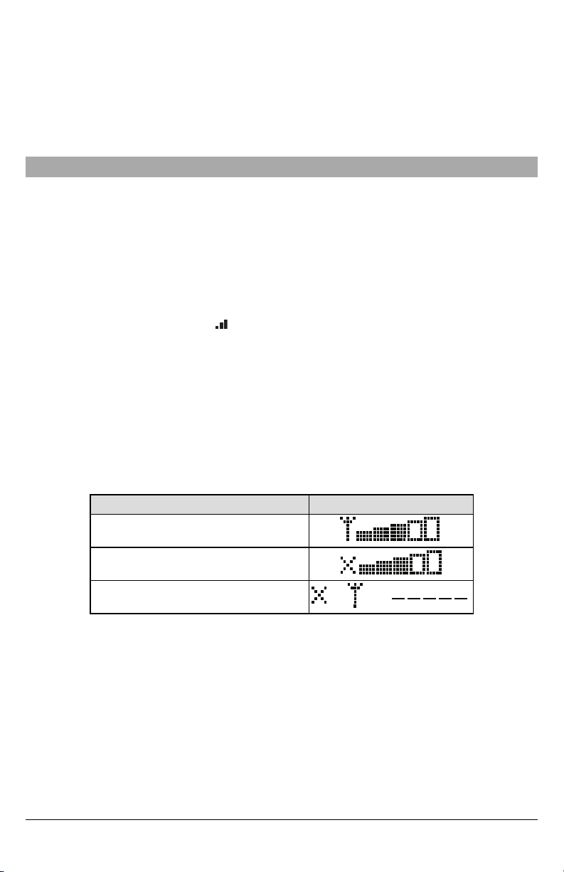
Cellular Signal Strength Display - LCD Keypad only
The cellular network signal strength can be checked onthe keypad LCD screen by entering installer programming section [850]. The LCD will indicate the SIM card activation status followed byup to five bars of
signalstrength. This displaywill automatically update every three seconds. For the relationship between
signal strength bars, CSQ level, and signal level in dBm, refer to “Radio Signal Strength” on pag e
10.
Table 4: Signal Strength Display
Description Display
SIM card active and current signal streng th
SIM card inactive and current signa l strength
Radio not registered
NOTE: If the required signal strength is too low with the panel in its current location, the panel must be
relocated or an external antenna is required.
If required, the following cellular extension antenna kits are available to theinstaller:
l GS-15ANTQ - 4.57m (15’) internal antenna extension kit(suitable for interior mounting).
l GS-25ANTQ - 7.62m (25’) external antenna extension kit(suitable for interior/exterior mounting).
l GS-50ANTQ - 15.24m(50’) external antenna extension kit (suitable for interior/exterior mounting).
Specific instructions for the installation of the extension antenna are included with the kit. Observe all the
electricalsafety instructions regarding the installation ofthe antenna. All the wiring of the equipment shall
be fullycompliant with the local rules and regulations.
3. If required, installthe antenna extension and perform the following steps to determine the best loc-
ation for placement of the antenna:
a. Disconnect the white whip antenna from the panel.
b. Attach one end of the antenna extension cable to the threaded antenna connector on the panel
and the other end to the external antenna.
12

4. Move the extension antenna to various locations whileobserving the two green LEDson the panel.
a. Continue to reposition the extension antenna until it receives an acceptable (minimum one
green LED ON solid) signal strength.
NOTE: Minimum strength is: green LED 1 flashing and yellow LED off. If green LED 1 is
b. Mount the supplied antenna extension bracket at the locationthat providesthe bestsignal
5. Alternately, reposition the panel to improve signal strength. Dismount the panel and move it to
another location to achieve the required signal strength. If thepanel is relocated to improve signal
strength, mount it in the new location.
6. When final panel/antenna locationis determined, continue at the Initial Panel Programming sec-
tion.
NOTE: If the SIM card is not activated, placement test will indicate the signal strength of the nearest cel-
NOTE: In between displaying signal strength, the signal strength LEDs will flash alternately if an inactive
flashing,relocation should be considered.
strength.
lular tower.
SIM card is used. The flashing indicatesthat the module isattempting to attach to the cellular network and willonlylast briefly.
Initial Panel Programming
Keypad Data Display
l Section-Toggle Option s: The number is displayed when toggle isON and the number isnot dis-
played when toggle isOFF. (e.g., toggle options displays: [--3--6--]. Options3 and 6 are ON, all others are OFF). Pressing keys 1 through 8 will alternately turn the toggle ON and OFF.
l HEX/Decimal Data: Valuesthat are provided with two defaults, separated by a “/” character, use the
format: hexadecimalfollowed by decimal equivalent (e.g., default [0BF5/3061]). Hexadecimal numbers are shown, with all leading zeroes, to the full field length defined for the number.
Entering HEX values at keypad
To enter HEX values at the keypad, press the * keybefore entering the HEX value. (e.g., to enter “C” at
the keypad, press [*][3])
Entering ASCII Characters at keypad
1. Press [*] and use scroll buttons [<] [>] to display “ASCII Entry” on the LCD screen.
2. Press [*] to select ASCII entry mode.
3. Use the [<] [>] scrollkeysto displaythe desired character and press [*] to save and exit ASCII.
4. Repeat the steps above to enter another ASCII character.
HS2016/2032/2064/2128 Initial Programming
For detailed information, refer to panelmanual section‘Alternate Communicator Set-up’. These sections
must be programmed at the panel keypad. Enter [ *][8] [Installer Code] [Section Number]. Record
any values that are modified from their default, in the appropriate worksheets for the panel or communicator.
1. In panelsection [377] ‘Communication Variables’,subsection [002] ‘Communication Delays’, sub-
subsection [1] ‘Communication Delay’, program 060 (seconds).
2. In panelsection [382] ‘Communicator Option 3’ set option [5] ON
NOTE: If this option isOFF, the yellow status LED on the communicator willindicate ‘Panel Supervision
Trouble’ (2 flashes) and the unit can not be programmed via the PC-LINK cable.
Activating the Communicator with C24 Communications
Installation of the 3G2080(R)E / LE2080(R) or TL2803G(R)E / TL280LE(R) requires activation with C24
Communications in order to operate. Please contact the central station (C24 Communications Master
Reseller) to confirm the required stepsto activate/program the communicator.
NOTE: NOTE: The SIM activation with the carrier can take several hours to complete. It is recom-
mended the activation be completed prior to arrival on the customer site to avoid possible install-
ation delays.
Once the SIM activation iscomplete, the communicator will automaticallyconnect and download its programming from C24 Communications.
SMS Command and Control
Certain functions can be performed on the alarm panel by remote, using SMS text messages. In addition, the system sends SMS messages to confirm commands. SMS programming options are accessed
13

through programming section [851].
The security system only responds to SMS messages sent from designated phone numbers (programmed in section [851]>[311]-[328]).
SMS Commands
l Stay arm the system
l Away arm the system
l Night arm the system
l Disarm the system
l Activate command output 1
l Activate command output 2
l Activate command output 3
l Activate command output 4
l Deactivate command output 1
l Deactivate command output 2
l Deactivate command output 3
l Deactivate command output 4
l System status request
l Alarm memory request
l Zone bypass
l Zone unbypass
SMS text messagesmust be formatted asfollows:
<function name><space><partition #><space><accesscode>
(e.g., Stay Arm partition 1 1234). Once the command is received and executed by the alarm system, a
confirmation text message is received.
NOTE: For more information about SMS commands and control functions, r efer to the Neo 1.1 User
Manual.
Communicator Status LEDs
The communicator has four on-board LED indicators. These include one yellow trouble LED, one red
network connection status LED and two green signal strength LEDs. The LED meaning is described in
this section.
Yellow Trouble LED
This yellow LED will flash to indicate a trouble on the unit. The number of flashes indicates the type of
trouble. See the table below for the coded flashes and the conditionswhich willactivate thetrouble status
LED.
Table 5: Yellow Trouble Status LED
# of
Flashes
Trou ble
# of
Flashes
Trou ble
2 Panel Supervision Trouble 8 Receiver Supervision Troub le
4 Not Applicable 9 FTC Trouble
5 Cellular Trou ble 10 C24 Communications Configuration Failure
6 Ethernet Trouble 12 Module Configuration Trouble
7 Receiver Not Available Trouble
NOTE: Only the highest priority trouble (2 flashes isthe highest priority trouble) is indicated. When this
trouble is restored, the next highest trouble will indicate, if present. This will continue until all
troubles have been cleared (yellow LED is not flashing).
The following paragraphs describe the conditionsassociated with the trouble indicated:
Panel Supervision Trouble (2 Flashes)
This trouble will be indicated when communication between the communicator module and the panel
fails. If the module can not communicate with the panel (e.g., loss of power to the panel) the communicator willsend the ‘Panel Absent Trouble Event’ message to the central station receiver. When communication returns, a ‘Panel Absent Restore Event’ is sent by the communicator to the central station
receiver. The reporting codes are ET0001 for trouble and ER0001 for restore. The panel absent event
always uses the primary receiver account code when communicating to the central station.
14

NOTE: The panel supervision trouble/restore are internally generated events by the communicator.
Trouble is generated if the communicator misses 6 polls. T rouble isrestored on receipt offirst poll
from the panel.
SIM Lock Trouble (4 Flashes)
This trouble occurs when the SIM lock feature has been enabled and the unit has been programmed
with the wrong PIN for the SIM card.
Cellular Trouble (5 Flashes)
This trouble is indicated for anyof the following 4 conditions:
1. Radio Failure: Trouble is indicated after 8 failed attempts to communicate with thecellular radio.
2. SIM Failure: Trouble is indicated after 10 failed attempts tocommunicate with the SIM.
3. Cellular Network Trouble: Trouble is indicated for loss of the registration to the network provider.
4. Insufficient Sig nal Strength: Trouble isindicated if calculated average signalstrength istoo low.
(Both green LEDsare OFF). Trouble willclear when the calculated average signalstrength is
above minimum (i.e., > CSQ 5).
NOTE: If Option [851][005] Bit 8 is Off, CSQ less than or equalto 4 will not trigger Cellular Trouble
Ethernet Trouble (6 Flashes)
This trouble is indicated when an Ethernet link between the transmitter and the local switch or router is
absent. This trouble will also be indicated if the unit failsto get Dynamic Host Control Protocol(DHCP) settings from the DHCP server. (Not active if Ethernet receivers are not programmed) .
Receiver Not Available (7 Flashes)
This trouble is indicated if the unit is not able to successfully initializewith any of the programmed receivers. Unprogrammed receivers are excluded. This trouble is also indicated if the cellular receiver APNs
have not been programmed in sections [205] and [215].
Receiver Supervision Trouble (8 Flashes)
This trouble is indicated when receiver supervision is enabled and communication between the communicator module and the receiver fails. Trouble is indicated if Ethernet 1 and/or cellular 1 is supervised
and does not receive a heartbeat from the receiver or if cellular is supervised and the unit does not
receive an acknowledgment to 4 heartbeats sent to the receiver.
FTC Trouble (9 Flashes)
This trouble is indicated when the unit fails to communicate module events to the central station. Trouble
is displayed after the unit has exhausted all communications attempts to all programmed receivers for
events generated bythe communicator.
Module Configuration Trouble (12 Flashes)
This trouble is indicated when the system account code or the receiver account have not been programmed. Disabled receivers are excluded.
Red Network Connection Status LED
TL280(R)E / TL280LE(R) / TL2803G(R)E only
BLINKING: Indicates communications in progress.
l Once quicklyfor outgoing Ethernet transmission.
l Twice quickly to indicate incoming Ethernet ACK/NACK.
OFF: This is the normal state of the red network connection status LED. There are no network connection issues present.
ON: There is a problem with the Ethernet or the cellular network connection. LED will be ON ifany of the
following occur: Ethernet cable is not connected, DHCP configuration times out, unit fails to get an IP
address from the cellular network, or Cellular connection has been reset.
(Green LED 1) (Green LED 2) and (Yellow LED) Signal Strength
NOTE: If the yellow LED is flashing, signalstrength in table below is not valid.
See Table 8 for troubleshooting flashing yellow LED.
15

Table 6: Radio Signal Strength
Signal
Strength
CSQ
Level
Yellow
LED
Green
LED 2
Green
LED 1
Signal
Level
dBm
Actio n Req uired
If this status persists and the yellow
LED shows 5 flashes, confirm that the
Radio Not
Ready
N/A N/A
Alternate
Flashing
Alternate
Flashing
SIM card is active.
Confirm cellular service is active in
N/A
area.
Relocate panel or install external
antenna.
No Signal 0 ON OFF OFF -108 .8 Check all antenna connections.
1 Bar 1 - 4
See
OFF Flashing
Note
2 Bars 5 -6 OFF OFF Flashing
3 Bars 7 - 10 OFF OFF ON
4 Bars 11-13 OFF Flashing ON
5 Bars 14 + OFF ON ON
Flashing
-108 ~ 103
-102 ~ -
99
-98 ~ 91
-90 ~ 85
-84 and
higher
Relocate panel or install external
antenna if yellow trou ble LED shows
five flashes.
Loca tion is OK. Cellular signal strength
is greater than CSQ 7.
NOTE: The communicator will indicate cellular trouble (yellow LED =5 flashes) if the calculated average
CSQ Level is 4 or less. The communicator signalstrength can be viewed remotely with C24 Communications.
Network Activity LEDs - Red and Green(TL2803G(R)E / TL280LE(R) only)
l Ethernet Activity: Red LED willblinkquicklyonce for transmit, or twice for receive.
l Cellular Activity: Green LED 2 willblinkquickly once for transmit, or twicefor receive
Communicator Troubleshooting
NOTE: For additional details:
l Refer to section[983] for troubleshootingthe firmware updates
l Refer to section[984] to view the trouble status
l Refer to section[985] for troubleshootingradio initialization
Table 7: Trouble Indications
Trou ble
indication
No
Indication
Yellow LED
– ON Solid
Trouble
Trou ble
Indicator
Possible
Digit
N/A No Power
N/A No Signal
02
Causes
Panel
Trou ble Possible Solution
l Check the power connectionsbetween the panel and
the communicator.
l Confirm PC-LINK cableis properly installed between
communicator and panel.
l Confirm that cellular network service is activein the
area.
l Ensure the antenna issecurely connected to the radio.
Check antenna stub cable is securely connected to the
radio.
l If anexternal antenna is used, ensure the antenna is
securelyscrewed on to the antenna cable connector.
Check external antenna for damage or open/short.
l Check section [382] toggleoption[5] is ON (Alternate
16

Trou ble
indication
LED – 2
Flashes
Yellow LED
– 5 Flashe s
Yellow LED
– 6 Flashe s
Yellow LED
– 7 Flashe s
Yellow LED
– 8 Flashe s
Yellow LED
- 9 Flashes
Yellow LED
– 12
Trou ble
Indicator
Possible
Digit
Supervision
05
06
07
08
Receiver Not
Supervision
09 FTC Trouble
0C
Configuration
Causes
Trouble
Cellular
Trouble
Ethernet
Trouble
Available
Receiver
Trouble
Module
Trou ble Possible Solution
Communicator Enabled).
l Ensure the PC-LINK cable between the panel and
communicator isconnected properly (not reversed) and
issecurely in place.
l Confirm that cellular serviceis available and active in the
area.
l Check all antenna connections.
l Ensure average radio signalstrength isCSQ 5 or
higher. (See Table 7 ).
l Ensure the SIM card is properly inserted into the SIM
card holder.
l Ensure the SIM card has been activated (could take up
to 24hrs after install).
l If this trouble persists, relocate thepanel (and
communicator) or installan external antenna extension
kit.
l Check with the ISP to confirm Internet service isactive in
the area.
l Ensure the Ethernet cable is securely inserted into the
RJ45 jackof the communicator and the
hub/router/switch.
l Check the linklight on the hub/router/switch is ON. If link
light is OFF, start the hub/router/switch.
l If DHCP isused, ensure that the unit has an assigned IP
address from the server. In Section [851] [992] verify a
valid IP address isprogrammed. If not, contact the
network administrator.
l If problem persists, replace the Ethernet cableand
RJ45 connector.
l Ensure that the Ethernet path has Internet connectivity.
l If using a static IP address, confirm that the gateway
and subnet mask are entered correctly.
l If thenetwork has a firewall, ensure thenetwork has the
programmed outgoing ports open (default UDP port
3060 and port 3065).
l Ensure that all the receivers are programmed for
DHCP or have the proper IP address and port number.
l Ensure the cellular receiver APNs have been
programmed with the access point name provided by
the cellular provider.
l If Common Mode is used, and only one path is initialized
while the other path is not successful, generate a
manual test tr ansmission over both paths or power
cycle the communicator to recover the ‘Receiver Not
Available’trouble.
l This trouble is indicated when supervisionis enabled
and the unit is not able to successfullycommunicate with
the receiver.
l If this trouble persists, contact the central station.
l The unit has exhausted all communicationsattempts to
all programmed receivers for events generated by the
communicator.
l Restart the system, if trouble persists, contact the
dealer.
l This indication appears when section [021] system
account code or sections[101]; [111]; [201]; and [211]
receiver account code have not been programmed.
17

Trou ble
indication
Flashes Trouble
All LEDs
flashing
together
Red and
Yellow
LEDs
flashing
together
Only Green
LEDs
flashing
Green
LEDs
alternating
Trou ble
Indicator
Digit
N/A
N/A
N/A
N/A
Possible
Causes
Boot Loader
Failed
Initialization
Sequence
Hardware
Default
Jumper
Radio Reset or
Radio
Initialization
Trou ble Possible Solution
Ensure that a valid account code has been entered in
these sections.
l Disconnectpower, then reconnect power to the
communicator module.
l The unit is still initializing please wait whilethe unitgets
its programming and establishes a connection to all
programmed receivers.
NOTE: This process may take several minutes to
complete.
l The hardware defaultjumper isinstalled and must be
removed. See Figure 3.
l If this status persistsand the yellow LED shows 5
flashes,confirm that the SIM card is active.
Ethernet/Cellular Programming Options
The programming sections described in this document can be viewed at the keypad LCD. To start programming enter: [*][8][installer cod e] [851] [section n umber], where section number is the 3- digit
section number referenced in this section.The programming worksheetsat the end of thisdocument can
be used to record the new values when programming changes have been made from thedefault values.
Installers may review/record programming optionsat the panelkeypad.
System Options
[001] Ethernet IP Address
Default (000.000.000.000)
Enter the IP address of the communicator. Ensure that the IP address isunique to the communicator on
the localnetwork. Format is 4 fields, each field isa 3 digit decimalnumber. Valid range: 000-255. If an IP
address is programmed in this section, the unit will operate withstatic IP (DHCP disabled). Sections [002]
and [003] must also be programmed when using static IP addresses.
NOTE: Default for this section is Dynamic Host Configuration Protocol(DHCP) enabled. When enabled,
the DHCP server will set values for: IP address [001], subnet mask[002], and gateway [003]. Programming an IP address in thissection willdisable DHCP (StaticIP).
[002] Ethernet IP Subnet Mask
Default (255.255.255.000)
Enter the Ethernet IP subnet mask of the communicator. Format is 4 fields, each field is 3 digits. Valid
range: 000-255.
NOTE: If DHCP is enabled, the DHCP server will assign the subnet mask for this section and the pro-
grammed value will be ignored.
[003] Ethernet Gateway IP Address
Default (000.000.000.000)
Enter the Ethernet gateway IP address of the communicator. The gateway IPaddress is required when
a router is used on the local network to reach the destination IP address specified in section [001].
Format is 4 fields, each field isa 3 digit decimalnumber. Validrange: 000-255.
NOTE: If DHCP is enabled, the DHCP server will assign the gateway IP address for this sectionand the
programmed value willbe ignored.
[004] Receiver Supervision Interval
Default (0087/135)
When receiver supervision is enabled (ON) in section [005] toggle option [3], the unit sends heartbeats to
Ethernet receiver 1 or cellular receiver 1 to test the communications path. Use this section to set the interval time (in seconds) when heartbeats will be sent to the receivers. Valid range 000A-FF FF seconds. If
the programmed valueis less than (000A/10) seconds, supervision is disabled.
18
 Loading...