

Tyco Safety Canada 17PG9933 Users manual
C
D
A
B
PG9933 (915MHz) Wireless Carbon Monoxide Detector
Installation and Operating Instructions
Read these instructions thoroughly before installation and use of the PG9933
The PG9933 is designed to monitor the CO gas level in residential dwellings and give
early warning before dangerous levels are detected. This device is intended to be used
with a compatible wir eless alarm system. The detector consists of an electrochemical
carbon monoxide sensor assembly coupled to a wireless tr ansmitter.
The Wireless Carbon Monoxide Alarm communicates with the control panel and can
send alarm, tamper and battery condition messages to the system receiver.
CAUTION: The detector expiry date is stamped on the detector. After the
expiry date, the detector should not be used - do not wait for end- of-life indication!
CAUTION: Unauthorized removal of the unit from the mounting bracket will
initiate a tamper alert.
Warnings:
The PG9933 wireless Carbon Monoxide detector shall be installed and used within an
environment that provides the pollution degree max 2 and overvoltages category II in
NON HAZARDOUS LOCATIONS, indoor only. T he equipment is designed to be
installed by SE RVICE PERSONS only; (SERVI CE PERSON is defined as a person
having the appropriate technical training and experience necessary to be aware of hazards to which that person may be exposed in performing a task and of measures to minimize the r isks to that person or other persons.)
Failure to properly install, test and maintain a CO detector may cause it to f ail, resulting in loss of life. Installation of the CO detector should not be used as a substitute
for proper installation, use and maintenance of fuel burning appliances, including
appropriate ventilation and exhaust systems.
This carbon monoxide detector is designed for indoor use only. Do not expose it to
rain or moisture. Do not knock or drop the detector. Do not open or tamper with the
detector as this could cause malfunction. The detector will not protect against the risk
of carbon monoxide poisoning if not properly installed.
CAUTION: This device will only indicate the presence of carbon monoxide gas at the
sensor. Car bon monoxide gas may be present in other areas. This carbon monoxide
alarming device is designed to detect carbon monoxide gas from ANY source of
combustion. It is NOT designed to detect smoke, fire or other gases unless the product
has been investigated and determined to comply with applicable r equirements.
WARNING! To comply with FCC and I C RF exposure compliance requirements, the
device should be located at a distance of at least 20 cm from all persons during normal
operation. The antennas used for this product must not be co- located or operated in
conjunction with any other antenna or transmitter.
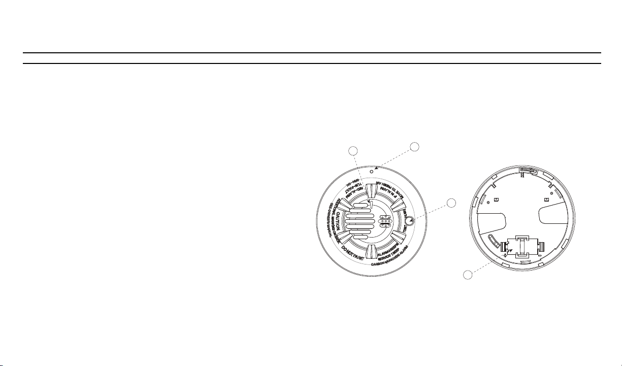
Figure 1: Wireless CO Detector
Legend
A. Alar m LED (see Table 1 for LED indications)
B. Tamper release opening
C. Test/Hush button
D. Battery compartment
E. Breakaway tab (see Figure 3)
Installation Instructions
Battery Installation
To replace the battery:
1. Remove the detector from its mounting base by twisting it counterclockwise.
Remove and dispose of the battery according to your local r egulations.
2. To ensure proper power-down sequence, wait a minimum of 20 seconds before
installing the new battery.
3. Install a new, 3-volt CR123A Panasonic lithium battery in the battery compartment observing correct polarity. If the battery is incorrectly inserted, remove
gently with a flathead screwdriver and correctly reinsert.
4. Reinstall the detector onto the mounting bracket by turning it clockwise.
5. After the power-up sequence, the green LED blinks once every 12 seconds to
indicate normal operation. If the battery is not installed correctly, the detector
will not operate and the battery may be damaged.
Enrollment
The 7-digit serial number located on the back of the CO detector housing must be
enrolled on the alarm systems control panel. See the Receiver Installation Manual and
follow the enrollment procedure. For placement tests remove the detector f rom its
backplate for one second (tamper) and then reattach. Wait at least 30 seconds for the
test result before activating again.
A general description of the procedure is provided in the following flow chart:
Step Procedure
1 See the Installation Manual for the alarm system that the device is being
enrolled on to ensure that the proper steps are used.
2 Enter the Device Enrollment option through the specified method and select the
appropriate option to add the new device.
3 Enroll the device by inserting the batteries to power up the device and enter the
Device ID. For example, ID No. 222-XXXX.
4 Select the desired Zone Number.
5 Configure any device parameters that ar e required. Enter the DEV
SETTINGS menu and select the required options to configure the detector.
6 Mount and test the detector. See Testing the CO detector for information on
testing the device. In addition, see the alarm systems Installation Manual that
the device is enrolled on for other test procedures that are required.
Selecting a Location
Selecting a suitable location is critical for the CO detector. The Consumer Product
Safety Commission ( CPSC) recommends to use at least one CO detector per household, located as near as possible to sleeping areas of the home, because the human
body is most vulnerable to the effects of CO gas during sleeping hours.
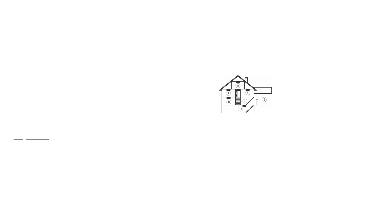
Figure 2: CO Detector Placement
Legend
A: Bedroom
B: Living Room
C: Kitchen
D: Basement
E: Garage
For added protection, install additional CO detectors in every bedroom and on every
level of your home. If your bedroom hallway is longer than 14 meters (40 feet), install
a CO detector at BOTH ends of the hallway. Install an additional detector 6 meter s
(20 feet) away from the furnace or fuel burning heat source. For maximum protection,
the detector should also be located outside primary sleeping areas or at each level of
your home. Mount the detector on a firm wall or ceiling.
DO NOT install CO detectors:
l In locations where temperature may be below 0 ºC (14 ºF) or above 40 ºC (104 ºF).
l In locations where humidity is below 10% or above 93% RH non-condensing.
l Near paint thinner fumes.
l Near air conditioners, furnaces, stoves, fireplaces and any other ventilation source
that may interfere with CO gas entering the detector.
l In locations where furniture or draperies may obstruct the air flow.
l In exhaust streams from gas engines, vents, flues or chimneys.
l Where dirt or dust could collect and block the sensor and prevent it from working.
l In locations that can be reached by children.
l In turbulent air from ceiling fans.
l In close proximity to an automobile exhaust pipe - this will damage the detector.
Mounting
E
The detector can be mounted on a wall or ceiling. For EN approved sites, only ceiling
installation is allowed.
The CO detector must be mounted with its bracket (when it is attached to its bracket
the tamper switch is pressed and the detector automatic reset is performed).
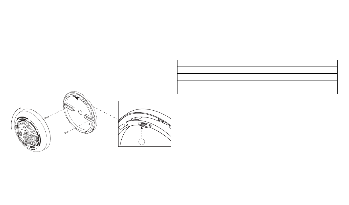
1. Refer to Figure 3 and install using scr ew locations as required. Maneuver the
mounting bracket so the screws are at the elbow of the screw slots and secure.
2. Fit the detector inside the mounting bracket by aligning it as shown in Figure 3
(detector’s alignment notch should be slightly offset from the mounting bracket
tamper release tab), then turn the detector in a clockwise direction until it clicks
into place.
3. Test the detector after completing the installation (as described in the Testing the
Detector section of this manual) and r efer to the alarm control panel installation
manual for additional information concerning the use of wireless devices.
Figure 3: Mounting the Detector
Tamper Protection
The PG9933 includes a tamper resistant feature that prevents removal f rom the mounting bracket without the use of a tool. To engage the tamper resistant feature, cut the
small breakaway tab ( marked E in Figure 3) located on the mounting bracket and then
install the detector. To remove the detector from the mounting bracket once it has been
made tamper r esistant, insert an appropriate tool into the tamper release opening located on the detector housing (marked B in Figure 1). Press and hold while simultaneously turning the detector counterclockwise.
Owner's Instructions
Testing the CO Detector
NOTE: P erforming a CO detector system test will generate an alarm transmission. Notify the central station before testing.
Perform a CO detector system test by pressing the T est/Hush button for a minimum of
6 seconds, the r ed LED flashes and the sounder emits a temporal 4 pattern.
Perform a CO detector local test by pressing the T est/Hush button for a minimum of 2
seconds, the sounder will emit 2 short beeps.
The following table indicates received signal strength indication.
LED Response Reception
Green LED blinks Strong
Orange LED blinks Good
Red L ED blinks Poor
No blinks Paired, no communication
IMPORTANT! Reliable reception must be confirmed. Therefore, "poor" signal
strength is not acceptable. If you receive a "poor" signal from the device, re-locate it
and re-test until a "good" or "strong" signal strength is received. For UL /UL installations, the test results must be "strong". See the alarm systems installation guide f or
detailed diagnostic tests.
Maintenance
Test the detector weekly to ensure proper operation of the detector. When low battery
is indicated (see Table 1 and Specifications) immediately replace the battery. Once a
month, use a vacuum cleaner to keep the air vents free of dust.
 Loading...