

Tyco Safety Canada 17LE4010 Installation Manual

3G4010/LE4010
3G (HSPA) Cellular Alarm Communicator
LTE Wireless Alarm Communicator
INSTALLATION MANUAL
Warning: This manual contains information on limitations regarding product use and function and information on the limitations as to liability of
the manufacturer. The entire manual should be carefully read.

3G4010/LE4010 Installation Manual
Contents
Section 1: Safety Information 3
Section 2: Introduction 4
2.1 Features 4
2.1.1 Technical Specifications 5
2.2 Identification of Parts 7
2.2.1 Description 7
Section 3: Installing the 3G4010/LE4010 9
3.1 C24 Communications Enrollment 9
Section 4: Connecting the 3G4010/LE4010 11
Section 5: Status LEDs 12
5.1 Operating Modes 12
5.1.1 Normal Mode 12
5.1.2 Service Mode 12
Section 6: Operating Principles 14
6.1 Simulated Landline Mode 14
6.2 Panel Transmission Monitoring (PTM) 14
6.3 Cellular Communications Sequence 14
6.4 Inputs 15
6.5 Outputs 15
6.5.1 Activating the Outputs 15
6.6 Reporting Codes 16
6.7 Swinger Shutdown 16
6.8 Hardware Default 17
6.9 Communicator Reset/Update 17
6.10 Low Power Radio Shutdown 18
6.11 SMS Command and Control 18
6.11.1 Arming/Disarming the Security Panel 18
6.11.2 Remote Control of PGM 18
6.12 Phone Number Call Direction 19
6.13 C24 Communications Remote Programming 20
Section 7: Troubleshooting Guide 21
7.1 LE4010 IM Wiring Diagrams 25
2

Section 1: Safety Information
Section 1: Safety Information
IMPORTANT
The equipment is fixed, wall-mounted and shall be installed in the position specified in these instructions (see
Figure 1: Parts). The equipment enclosure must be fully assembled and closed, with all the necessary
screws/tabs and secured to a wall before operation. Internal wiring must be routed in a manner that prevents:
- Excessive strain on wire and on terminal connections
- Loosening of terminal; connections
- Damage of conductor insulation
WARNING: Never install this equipment during a lightning storm!
Instruct the end-user to:
- Not attempt to service this product. Opening or removing covers may expose the user to dangerous voltages
or other risks. Any servicing shall be referred to trained service persons only.
- Use authorized accessories only with this equipment.
Do not dispose of the battery in fire or water. Disposing of the battery in a fire will cause rupture and explosion.
Do not dispose of the waste battery as unsorted municipal waste. Consult your local regulations and /or laws
regarding recycling with regard to this lead-acid battery. Doing so will help protect the environment. Some of
the materials that are found within the battery could become toxic if not disposed of properly and may affect
the environment.
All circuits are classified for UL installations as Power Limited/Class II Power Limited except for the battery
leads which are not power limited. Do not route any wiring over circuit boards. Maintain at least 1” (25.4mm)
separation. A minimum 1/4” (6.4mm) of separation must be maintained at all points between Power Limited
wiring and all other non-Power Limited wiring. Route wires as indicated above.
This equipment, 3G4010/LE4010, is fixed and shall be installed by Service Persons only (Service Person is
defined as a person having the appropriate technical training and experience necessary to be aware of hazards
to which that person may be exposed in performing a task, and of measures available to minimize the risks to
that person or other persons). It shall be installed and used within an environment that provides the pollution
degree max 2, over voltages category II, in non-hazardous, indoor locations only. This manual shall be used
with the Installation Manual of the relevant alarm control panel. All instructions specified within that manual
must be observed.
The performance of the 3G4010/LE4010 depends greatly on cellular network coverage. Therefore, it should
not be mounted without first performing placement tests to determine the best location for reception (minimum
of one green LED ON). Optional antenna kits – LTE-8ANT, LTE-15ANT, LTE-25ANT, LTE-50ANT
(8ft/2.4m, 15ft/4.6m, 25ft/7.6m or 50ft/15.2m) – are available.
3

3G4010/LE4010 Installation Manual
Section 2: Introduction
This manual covers two communicator models, the 3G4010 and the LE4010. They are referred to throughout
this manual as 3G4010/LE4010 unless otherwise indicated.
Both models send alarm system information to a Sur-Gard System I-IP, II, III, IV or 5 receiver. The 3G4010
uses the 3G (HSPA) or 2G (GPRS) cellular network. The LE4010 uses the LTE or 3G wireless network. The
3G4010/LE4010 can be used with UL/ULC Listed compatible control units, as indicated in the manufacturer's
installation instructions.
Note: These communicators are designed to work with the Contact ID communication format as described in
the SIA DC-05 standard and the SIA DC-03 standard for 300 baud. Before completing the field installation of
the alarm monitoring system please ensure communication with the supervising central station is successful by
sending several events and getting confirmation that they have been received.
2.1 Features
l Dual-band UMTS/HSPA; Penta-Band LTE (LE4010); Quad-Band GSM/EDGE Radio
l Advanced Carrier Selection
l Bi-color Wireless Signal Strength Indicator
l 3G (HSPA) / 2G (GPRS) ; LTE or 3G (LE4010) Internet communication with Sur-Gard SG-System I-IP
/ II / III / IV / 5
l Compatible with 4-digit or 10-digit Contact ID communication format as described in SIA DC-05
Standard and the SIA DC-03 standard for 300 baud. Example of suitable compatible alarm panels:
DSC Models PC1864, PC1832, PC1616, PC4020. For LE4010, the following alarm panels are also compatible: HS2128, HS2064, HS2032, HS2016
l Panel Transmission Monitoring for up to four phone numbers
l Simulates landline
l Switches automatically to the 3G (HSPA) or 2G (GPRS) / LTE or 3G (LE4010) network in the event of
landline trouble (e.g., line down)
l Four Programmable (NO/NC/SEOL) Inputs
l 12V 1.2Ah battery (optional, not included)
l Case Tamper Output
l Landline overvoltage protection
l Four Programmable Outputs
l DLS support for status, firmware updates and remote debug enable
l Remote Firmware Upgrade
l Remote Diagnostics
l Panel Format Detection
l SMS Command and Control
l Phone number call direction
l Easy enrollment with C24 Communications via web or mobile interface
4

2.1.1 Technical Specifications
2.1.1 Technical Specifications
The input voltage to the 3G4010/LE4010 can be drawn from the UL/ULC Listed control panel or provided by
an external UL/ULC Listed power supply rated for the application (external power-limited source).
Note: The power supply must be Class 2, Power Limited. For residential applications a suitable power adaptor
is model DSC ADP1310(W)-NAU or DSC ADP1320-NAU (for USA) and model DSC ADP1310(W)-NA (for
Canada).
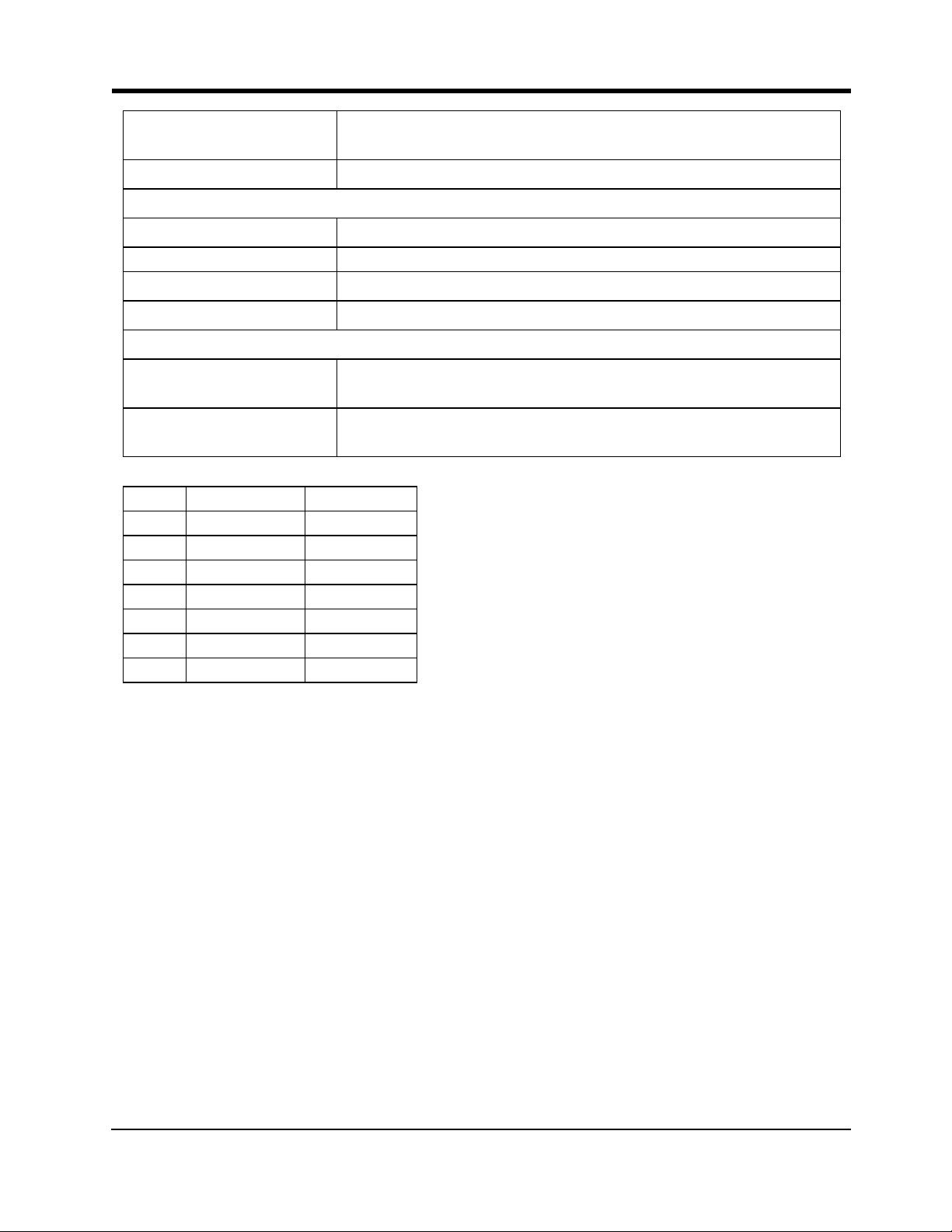
Table 4-1 Ratings
Power Supply Ratings
Input Voltage:
Current Consumption
Average Current (standby with PSTN
connected):
Average Current (standby without
PSTN connected):
Transmission Curr ent (no battery): 225mA*
* Plus any current drawn from the 3G4010/LE4010 AUX+ terminal
Working Voltage Range
With Battery: 11-14Vdc
Without Battery: 9 -14Vdc
Battery T ype:
Battery charging voltage: 13.75Vdc
Battery charge curr ent limit: 360mA
NOTE: Battery must be replaced every 3-5 years.
NOTE: When using the battery, use DSCADP 1310-NAU(W) or ADP 1320-NAU power adapter
9-14Vdc (use separately listed control panel or power supply) or 13.8Vdc (use DSC ADP1310
(W)- NAx or ADP1320-NAx power adapter)
40mA*
55mA*
sealed, rechargeable type, rated 12V/1.2Ah
(for 24hr standby time)
Operating frequency - 2G
(GSM/GPRS/E DGE):
Operating frequency - 3G
(UMTS/HSPA):
For LE4010 operating frequencies, see
table below.
Antenna gain: 2.0dBi
Environmental Specifications
Operating temperature: 0°C-49°C (32°F-120°F)
Humidity: 93%RH Maximum (non-condensing)
Mechanical Specifications
850/1900MHz
850/1900MHz
5
3G4010/LE4010 Installation Manual
Dimensions (metal enclosure,
painted):
Weight (without battery): 900g / 3.2oz
Simulated Telco Loop specif ications (TIP/RING)
On-Hook Voltage: 12Vdc
Off-Hook Voltage (Maximum): 22Vdc
Loop Current : 25mA
Loop Resistance : 600 Ohms
Alternate construct ion
Dimensions (enclosure for
3G4010/LE4010):
Weight (alter nate construction enclosure
without batter y):
138mm x 224mm x 55mm / 5.4” x 8.8” x 2.2”
138mm x 257mm x 55mm / 5.4" x 8.8" x 2.2"
1300g / 2.8lbs
Table 4-2 LE4010 Operating Frequencies
Band Transmit Band (Tx) Receive Band (Rx)
LTE B2 1850 - 1910 MHz 1930 - 1990 MHz
LTE B4 1710 - 1755 MHz 2110 - 2155 MHz
LTE B5 824 - 849 MHz 869 - 894 MHz
LTE B12 698 - 716 MHz 728 - 746 MHz
LTE B13 777 - 787 MHz 746 - 756 MHz
UMTS B2 1850 - 1910 MHz 1930 - 1990 MHz
UMTS B5 824 - 840 MHz 869 - 894 MHz
6
2.2 Identification of Parts
CON3
LED2
BAT +
OPE N
+
LED1
BAT -
-
LED4
LED3
UA673
SE
R
IAL NU MB E R
1
44
5
3
2
8
6
9
10
11
13
12
15
14
4
tie wrap
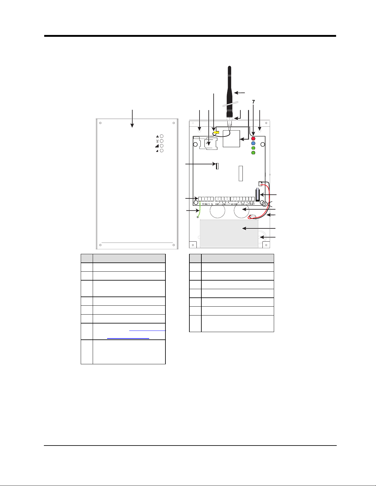
2.2 Identification of Parts
Part
1 Metal Casing
2 3G/LTE Antenna
Antenna Mounting Hard-
3
ware
4 Anchor Screw Holes (3mm)
5 Antenna Connector
6 SIM Card Holder
Status LEDs (Table Section
7
3G (HSPA) Radio Module
8
(3G4010); LTE Radio Mod-
5: : Status LEDs)
9 PC-Link Connector
10 Tamper Switch
11 Terminal Blocks
12 Battery Leads
13 Cable Entry
14 Earth Ground Wire
15
Part
12V/1.2Ah Battery
(not included)
ule (LE4010)
2.2.1 Description
This 3G4010/LE4010 manages transmissions to a central station and can simulate the landline in the event of
trouble (e.g., landline down) or even substitute the landline completely in areas where the 3G or 2G cellular
service is provided and a landline is not available.
The 3G4010/LE4010 has the capability of communicating alarm signals via the 3G or 2G data network. This
capability ensures a fast, reliable path to central stations equipped with a Sur-Gard System I-IP / II / III / IV / 5
receiver. By connecting a 3G4010/LE4010 to a control panel's standard PSTN interface, telephone-based
7

3G4010/LE4010 Installation Manual
Contact ID or SIA signals are decoded and seamlessly routed through the LTE, 3G or 2G network to any of
the compatible receiver options.
The performance of the 3G4010/LE4010 depends greatly on cellular network coverage. Therefore, it should
not be mounted without first performing placement tests to determine the best location for reception (minimum
of one green LED ON). Optional antenna kits – LTE-8ANT (8ft/2.4m), LTE-15ANT (15ft/4.6m), LTE-25ANT
(25ft/7.6m) and LTE-50ANT (50ft/15.2m) – are available.
For UL Residential Fire and Burglary installations, the 3G4010/LE4010 is listed as a sole means of communication or as a back up when used in conjunction with a POTS line (dialer).
For UL Commercial Burglary installations, the 3G4010/LE4010 is listed as a sole means of communication
(supervision window of 200s required at monitoring station) or as a back-up when used in conjunction with a
POTS line (dialer). The 3G4010/LE4010 shall be powered from any compatible listed control unit or compatible listed power supply that complies with the ratings specified on page 1. The power supply shall be listed for burglary applications and provide a minimum of 4 hours standby power capabilities. An example of a
suitable listed compatible control unit is the DSC Model HS2128 with an AUX output rated 11.1 - 12.6VDC.
An example of a suitable Listed power supply is DSC Model HSM2204 with an AUX output rated 11.6 -
12.6VDC.
For ULC Commercial Fire Monitoring Installations the 3G4010/LE4010 can be used in the following configurations:
1. Active communication system with 180 seconds supervision (Heartbeat sent to signal receiving centre
every 90 sec.).
2. Passive communication system in conjunction with a another communication path (e.g. DACT) (there is
no heartbeat sent in this configuration, only periodic test transmission ). Alarm signals must be sent simultaneously over both communication paths (Cellular and DACT). Every 24 hours, a test transmission
must be sent to the signal receiving centre over each communication path. Each communication path
shall be monitored for integrity (DACT shall have line monitoring enabled and 3G4010/LE4010 shall
have cellular connection supervision enabled).
For ULC Commercial Burglary Monitoring Installations the 3G4010/LE4010 can be used in the following
configurations:
1. Active communication system with 180 seconds supervision and heartbeat sent to signal receiving
centre every 90 sec.
2. Passive communication system line security P1 (single communication channel) or line security P2
(used as backup in conjunction with another communication path (e.g. DACT)). There is no heartbeat
sent in this configuration, only periodic test transmissions. Every 24 hours, a test transmission must be
sent to the signal receiving centre over each communication path. Each communication path shall be
monitored for integrity (DACT shall have line monitoring enabled and 3G4010/LE4010 shall have cellular connection supervision enabled). For Level P2 the working communication path shall report the
failure of the other channel within 240s.
For ULC Residential Fire and Burglary installations the 3G4010/LE4010 is listed as a sole means communication or as a back up when used in conjunction with a POTS line (dialer).
8
Section 3: Installing the 3G4010/LE4010
Section 3: Installing the 3G4010/LE4010
3.1 C24 Communications Enrollment
The 3G4010/LE4010 requires enrollment with C24 Communications to operate. For more information, please
visit www.connect24.com, contact C24 Communications customer service at 1-888-251-7458 (US) / 1-888955-5583 (Canada) or contact the central station to inquire if they are a C24 Communications Master Reseller.
Note: Enrollment with C24 Communications should be performed before turning on the 3G4010/LE4010 unit.
Before inserting or removing the SIM card, please ensure the unit is turned off.
Step 1 - Initialize the 3G4010/LE4010 with C24 Communications
The 3G4010/LE4010 can be initialized with C24 Communications by:
web - www.connect24.com
mobile - m.connect24.com
To complete enrollment, a C24 profile, installer ID/PIN (or web credentials) and the 20-digit SIM number are
required.
Note: The SIM activation process with the cellular carrier typically takes between five and ten minutes to complete.
Step 2 - Determine the Best Signal Location
1. Detach the front cover by removing the four screws.
2. Apply power (DC and/or battery). The 3G4010/LE4010 is now in Placement Test mode.
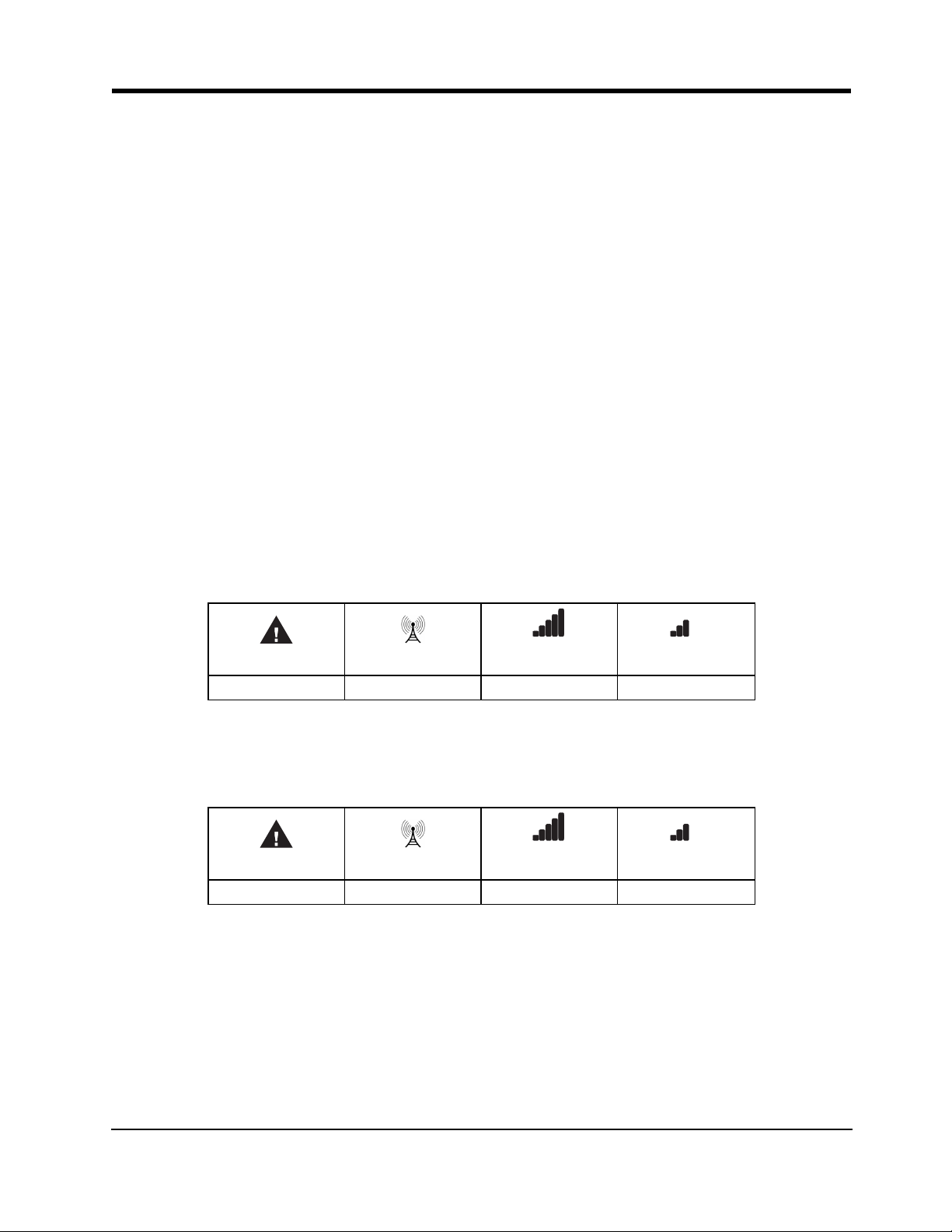
Step 2a – SIM Card Is Activated.
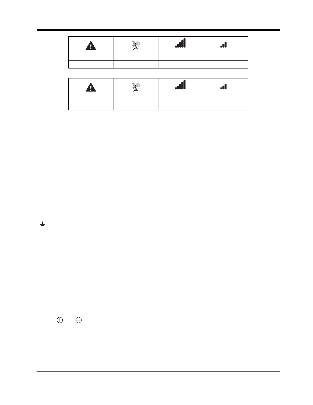
The red LED is on solid, the blue LED is off and the signal strength LEDs display the average signal strength.
In this state, the 3G4010/LE4010 is registered to the network.
Red Blue
ON OFF - -
Yellow/Green
(Top)
Yellow/Green
(Bottom)
If the signal strength is too low (bottom signal LED off or flashing), the 3G4010/LE4010 will proceed to Step
3: scan for, and attach to, carriers with sufficient signal strength. If the 3G4010/LE4010 is connected to a car-
rier with sufficient signal strength (minimum of bottom signal strength LED on solid), it proceeds to Step 4.
Step 2b – SIM Card Is Not Activated
The red LED flashes, the blue LED is off and the signal strength LEDs display the average signal strength.
Red Blue
FLASHING OFF - -
Yellow/Green
(Top)
Yellow/Green
(Bottom)
In this state, the 3G4010/LE4010 is unable to register to the network because it is inactive. The signal strength
indicated is from any nearby cell tower (including cellular towers belonging to non-roaming partners) and
does not necessarily reflect the signal strength of the intended network. The 3G4010/LE4010 remains in this
state until the SIM is activated. Once the SIM is activated, the 3G4010/LE4010 proceeds to Step 2a.
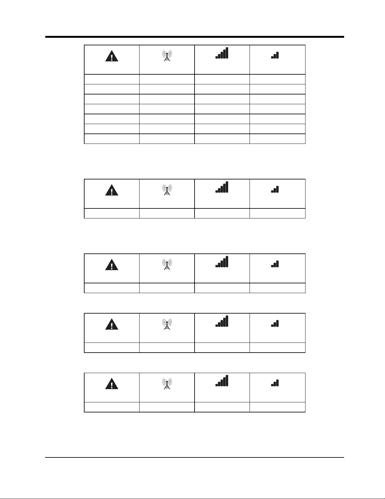
Step 3 – Carrier Scanning Due To Insufficient Signal Strength
The 3G4010/LE4010 scans the surrounding network and connects to the carrier to provide a signal strength of
at least 7 CSQ. While this action is being performed, all four LEDs activate to show a scanning sequence in
progress. The LEDs cycle from top to bottom and then bottom to top until the 3G4010/LE4010 connectes to a
carrier with a signal strength above 7 CSQ (minimum of bottom signal strength LED on solid).
9
3G4010/LE4010 Installation Manual
Red Blue
FLASH ON OFF OFF OFF
OFF FLASH ON OFF OFF
OFF OFF FLASH ON OFF
OFF OFF OFF FLASH ON
OFF OFF FLASH ON OFF
OFF FLASH ON OFF OFF
FLASH ON OFF OFF OFF
Yellow/Green
(Top)
Yellow/Green
(Bottom)
Once this is completed, the 3G4010/LE4010 proceeds to Step 4.
Step 4 - Acquire C24 Communications Programming
The red LED is on solid and the blue LED flashes. The flashing blue LED indicates that the 3G4010/LE4010
has requested programming from C24 Communications and is waiting for a response.
Red Blue
ON FLASHING - -
Yellow/Green
(Top)
Yellow/Green
(Bottom)
Once remote programming is completed, the blue LED switches to solid and the 3G4010/LE4010 proceeds to
Step 5.
Step 5 – Receiver Initialization
The red and blue LED’s are both on solid and the signal strength LEDs are off.
Red Blue
ON ON OFF OFF
Yellow/Green
(Top)
Yellow/Green
(Bottom)
When the 3G4010/LE4010 sends a request to communicate with the central station, the top signal strength
LED begins flashing.
Red Blue
ON ON FLASHING OFF
Yellow/Green
(Top)
Yellow/Green
(Bottom)
When the central station communicates back to the 3G4010/LE4010, the top signal strength LED turns on
solid.
Red Blue
ON ON ON OFF
Yellow/Green
(Top)
Yellow/Green
(Bottom)
When the 3G4010/LE4010 sends a request to communicate to the next central station, the bottom signal
strength LED begins flashing...
10
Section 4: Connecting the 3G4010/LE4010
Red Blue
ON ON ON FLASHING
Yellow/Green
(Top)
Yellow/Green
(Bottom)
...and turns on solid when it receives a communication back from the central station.
Red Blue
ON ON ON ON
Yellow/Green
(Top)
Yellow/Green
(Bottom)
If at least one of the central stations does not respond back to the communicator, the signal strength LED corresponding to that central station turns off. Once the initialization sequence is complete, the 3G4010/LE4010
switches to steady state operation.
Step 6 - Mount the 3G4010/LE4010
1. Power down the 3G4010/LE4010 by removing the DC power source and battery leads.
2. Using the cabinet, mark the four screw locations. Drill the anchor screw holes.
Note: Check for cable conduits and water pipes before drilling.
3. Using anchor screws (not provided), mount the cabinet to the wall.
4. Run the cables through the cable entry [13] or through the cabinet knockouts.
5. Complete the connections on the terminal blocks [11].
Note: Ensure that power and Telco circuit connections are made only after the cabinet has been secured to the
building or structure, and has been connected to the protective earth ground. Descriptions of the terminals can
be found in the ‘Connecting the 3G4010/LE4010’ section.
6. Reattach the front cover [1] securely to the cabinet.
Note: Please refer to the end of this manual for wiring diagrams.
Section 4: Connecting the 3G4010/LE4010
(1) Earth Ground - This terminal must be connected to the Mains Earth, in order to comply with the Tele-
communications Network Safety Standards (Overvoltage Protection Requirements).
TIP (2) / RNG (3) External Telephone Line - These terminals must be connected directly to the incoming telephone line.
T1 (4) / R1 (5) Internal Telephone Line - These terminals must be connected to the TIP and RING of the control panel.
COM (6,12) Common - This terminal is connected internally to Power Ground.
PGM1 (7), PGM2 (8), PGM3 (9), PGM4 (10) Programmable Open-collector Outputs - These outputs can be
activated by programmed events. Refer to ‘Activating the Outputs’ for details. The maximum current sink of
each output must not exceed 50mA.
AUX+ (11) Auxiliary Output - 9 to 14VDC Output, 500mA PTC Protected.
Note: Electrical current drawn from this terminal is drawn directly from the power supply. This must be added
to the 3G4010/LE4010 current when determining the total draw on the host panel or power supply.
Z1-Z4 (13-14-15-16) Programmable Inputs - These terminals can be set up to trigger events. Refer to ‘Inputs’
for details.
DC IN (17), (18) Device Power Supply - These terminals must be connected to a rated power supply. If
the primary supply does not include a backup battery, connect the battery leads (red and black wires, [12] in
Figure 1) to a 12V, 1.2 Ah battery.
11
 Loading...