

Tyco Safety Canada 17LE4000 User Manual

LE4000
LTE Wireless Alarm Communicator
Installation Manual
V5.0
Warning: This manual contains information on limitations regarding product use and function and information on the limitations as to liability of the
manufacturer. The entire manual should be carefully read.
LE4000 Installation Manual
0.1 TOC
Section 1: Introduction 4
1.1 Features 4
1.2 Technical Specifications 4
Section 2: Identification of Parts 6
Section 3: Installing the LE4000 7
Section 4: Connecting the LE4000 10
Section 5: Status LEDs 11
5.1 Operating Modes 11
5.2 Normal Mode 11
5.3 Service Mode 11
Section 6: Operating Principles 13
6.1 Simulated Landline Mode 13
6.2 Panel Transmission Monitoring (PTM) 13
6.3 Cellular Communications Sequence 13
6.4 Inputs 14
6.5 Outputs 14
6.5.1 Activating the Outputs 14
6.6 Reporting Codes 15
6.7 Swinger Shutdown 15
6.8 Hardware Default 16
6.9 Communicator Reset/Update 16
6.10 Low Power Radio Shutdown 17
6.11 SMS Command and Control 17
6.11.1 Arming/Disarming the Security Panel 17
6.11.2 Remote Control of PGM 17
6.12 Phone Number Call Direction 19
Section 7: Troubleshooting Guide 20
Section 8: LE4000 Wiring Diagrams 24
2

Safety Information
IMPORTANT
The equipment is fixed, wall-mounted and shall be installed in the position specified in these instructions. The equipment enclosure
must be fully assembled and closed, with all the necessary screws/tabs and secured to a wall before operation. Internal wiring must be
routed in a manner that prevents:
- Excessive strain on wire and on terminal connections
- Loosening of terminal; connections
- Damage of conductor insulation
WARNING:
Instruct the end-user to:
- Not attempt to service this product. Opening or removing covers may expose the user to dangerous voltages or other risks. Any ser-
vicing shall be referred to trained service persons only.
- Use authorized accessories only with this equipment.
Do not dispose of the battery in fire or water. Disposing of the battery in a fire will cause rupture and explosion.
Do not dispose of the waste battery as unsorted municipal waste. Consult your local regulations and /or laws regarding recycling with
regard to this lead-acid battery. Doing so will help protect the environment. Some of the materials that are found within the battery
could become toxic if not disposed of properly and may affect the environment.
This equipment, LE4000, is fixed and shall be installed by Service Persons only (Service Person is defined as a person having the
appropriate technical training and experience necessary to be aware of hazards to which that person may be exposed in performing a
task, and of measures available to minimize the risks to that person or other persons). It shall be installed and used within an envir-
onment that provides the pollution degree max 2, over voltages category II, in non-hazardous, indoor locations only. This manual
shall be used with the Installation Manual of the relevant alarm control panel. All instructions specified within that manual must be
observed.
Never install this equipment during a lightning storm!
Approvals Information
UL Residential Fire and Burglary installations, the LE4000 is listed as a sole means of communication or as a back up when used
For
in conjunction with a POTS line (dialer). For UL Residential Fire installations, the LE4000 must be connected to a UL-listed power
supply with a minimum of 24 hours standby power or powered using the ADP1310(W)-NAU and a 2200mAh battery.
For UL Commercial Burglary installations, the LE4000 is listed as a sole means of communication (supervision window of 200s
required at monitoring station) or as a back-up when used in conjunction with a POTS line (dialer).
The LE4000 shall be powered from any compatible listed control unit or compatible listed power supply that complies with the ratings
specified on page 1. The power supply shall be listed for burglary applications and provide a minimum of 4 hours standby power cap-
abilities. An example of a suitable listed compatible control unit is the DSC Model PC1864 with an AUX output rated 11.1 -
12.6Vdc. An example of a suitable Listed power supply is DSC Model PC5204 with an AUX output rated 11.6 - 12.6Vdc.
For ULC Commercial Burglary installations the LE4000 is listed as a passive communication system with communication line secur-
ity level P1 when used as single communication path or P2 when used as a back up in conjunction with a POTS line (dialer). The
LE4000 is also listed for Active line security levels A1-A4 (90 seconds heartbeat enabled and supervision window of 180s required
at monitoring station receiver). For ULC Commercial Burg installations, the LE4000 must be connected to a ULC-listed power
supply with a minimum of 24 hours standby power or powered using the ADP1310(W)-NA and a 2200mAh battery. The LE4000
can be used in commercial burglary applications up to Security Level IV.
For ULC Residential Fire and Burglary installations the LE4000 is listed as a sole means of communication or as a back up when
used in conjunction with a POTS line (dialer). For ULC Residential Fire installations, the LE4000 must be connected to a ULC-
listed power supply with a minimum of 24 hours standby power or powered using the ADP1310(W)-NA and a 2200mAh battery.
3
LE4000 Installation Manual
Section 1: Introduction
The LE4000 is a cellular communicator that sends alarm system information to a Sur-Gard System I-IP, II, III, IV or 5 receiver
through an LTE or 3G wireless network. This cellular communicator can be used with UL/ULC Listed compatible control units, as
indicated in the manufacturer's installation instructions.
The performance of the LE4000 depends greatly on cellular network coverage. Therefore, it should not be mounted without first per-
forming placement tests to determine the best location for reception (minimum of one blue/green LED ON). Optional antenna kits –
LTE-8ANT (8ft/2.4m), LTE-15ANT (15ft/4.6m), LTE-25ANT (25ft/7.6m) and LTE-50ANT (50ft/15.2m) are available.
Note: The LE4000 is designed to work with the Contact ID communication format as described in the SIA DC-05 standard, as well
as the SIA communications format as described in the SIA DC-03 standard. Before completing the field installation of the alarm mon-
itoring system please ensure communication with the supervising central station is successful by sending several events and getting
confirmation that they have been received.
1.1 Features
Penta-Band
l
Advanced Carrier Selection
l
Cellular Signal Indicator
l
LTE /3G / Internet communication with Sur-Gard SG-System I-IP / II / III / IV / 5
l
Compatible with 4-digit or 10-digit Contact ID communication format as described in SIA DC-05 Standard and the SIA DC-
l
LTE; Dual-band UMTS Radio
03 standard for 300 baud. Example of suitable compatible alarm panels:
DSC Models HS2128, HS2064, HS2032, HS2016, PC1864, PC1832, PC1616, PC4020.
Panel Transmission Monitoring for up to four phone numbers
l
Simulates landline
l
Switches automatically to the LTE or 3G network in the event of landline trouble (e.g., line down)
l
DLS support for status, firmware updates and remote debug enable
l
Remote Firmware Upgrade
l
Remote Diagnostics
l
Case and Wall Tamper
l
Panel Format Detection
l
Programmable Input
l
Programmable Output
l
1.2 Technical Specifications
The input voltage to the LE4000 can be drawn from the UL/ULC Listed control panel or provided by an external UL/ULC Listed
power supply (with battery back-up) rated for the application (external power-limited source).
Power Supply Rating
Input Voltage Class: Class 2, power limited
Compatible External Power Adapters ( 2-prong):
Input Voltage (Nominal): 13.8VDC required
Input Current: 700mA
DSC ADP1310(W)-NAU (US) / ADP1310(W)-NA (Canada)
For UL/ULC listed installations, the input rating for the external power
NOTE:
adapter is 120VAC/60Hz/0.4A.
4
Average Current: 40mA*
Peak Current ( no battery): 180mA*
1.2 Technical Specifications
Peak Current ( with battery):
Battery: NiMH, rated 7.2V, 2.2Ah
Battery Charging Voltage (maximum): 9.1VDC
Battery Charging Current: 160mA
Battery StandbyTime:
Cellular
3G Bands B2, B5.
LTE Bands B2, B4, B5, B12, B13 (See Table Table 3-1 : Band Frequencies)
Antenna Gain
Environ mental Specifications
Operating temperature: 0°C-49°C (32°F-120°F)
Humidity: 93% RH Maximum (non-condensing)
Mechan ical Specifications
Dimensions (mm): 125mm (W) x220mm (H) x 31mm (D)
Dimensions (inches): 4.9” x 8.7” x 1.2”
350mA*
* Plus any curent draw from LE4000 + ve terminal
24 hours
NOTE: Battery must be replaced every 3-5 years.
4.40 dBi
Weight (without battery): 400g / 1.2oz
Simulated Telco Loop Specifications
On-Hook Voltage: 12VDC
Off-Hook Current: 24mA
Loop Current: 25mA
Loop Resistance: 600 Ohms
Table 3-1 Band Frequencies
Band Transmit Band (Tx) Receive Band (Rx)
LTE B2 1850 - 1910 MHz 1930 - 1990 MHz
LTE B4 1710 - 1755 MHz 2110 - 2155 MHz
LTE B5 824 - 849 MHz 869 - 894 MHz
LTE B12 698 - 716 MHz 728 - 746 MHz
LTE B13 777 - 787 MHz 746 - 756 MHz
UMTS B2 1850 - 1910 MHz 1930 - 1990 MHz
UMTS B5 824 - 840 MHz 869 - 894 MHz
5
2
5
3
6
14
13
10
8
2
9
11
12
15
1
4
7
LE4000 Installation Manual
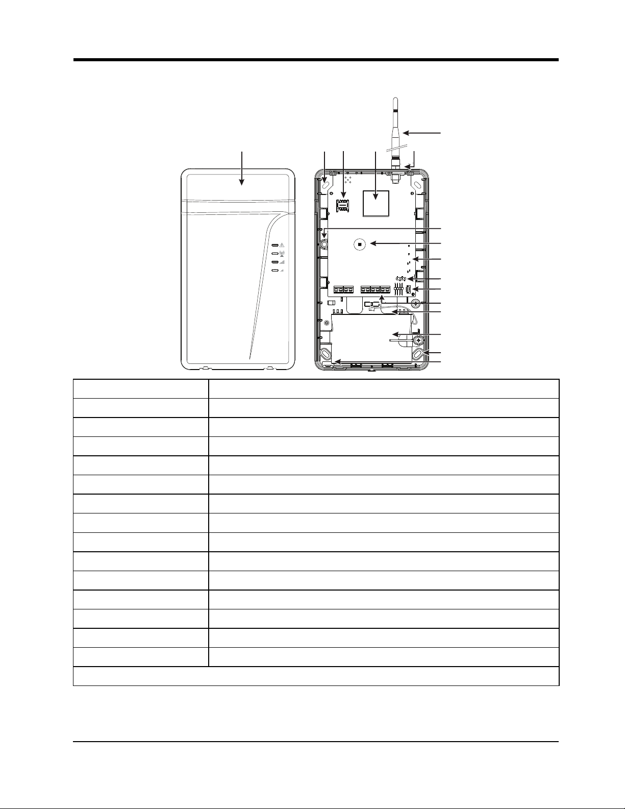
Section 2: Identification of Parts
1 Plastic casing
2 Anchor screw holes(3mm)
3 SIM card holder
4 LTE radio module
5 LET external antenna*
6 Antenna mounting hardware
7 Wall tamper switch
8 Cover tamper switch
9 Status LEDs (see "Status LEDs" on page 11)
10 PC-Link connector
11 Battery connector
12 Terminal blocks
13 Cable entry
14 7.2V - 2.2Ah battery (optional)
15 Cable run knockout
* Use only DSC provided antenna.
6
Section 3: Installing the LE4000
Section 3: Installing the LE4000
C24 Communications Enrollment
The LE4000 requires enrolment with C24 Communications to operate. For more information, please visit www.connect24.com, con-
tact C24 Communications customer service at 1-888-251-7458 (US) / 1-888-955-5583 (Canada) or contact the central station to
inquire if they are a C24 Communications Master Reseller.
Note: Enrollment with C24 Communications should be performed before turning on the LE4000 unit.
Before inserting or removing the SIM card, please ensure the unit is turned off.
Step 1 - Initialize the LE4000 with C24 Communications
The LE4000 can be initialized with C24 Communications by:
web - www.connect24.com
mobile - m.connect24.com
To complete enrollment, a C24 profile, installer ID/PIN (or web credentials) and the 20-digit SIM number are required.
Note: The SIM activation process with the cellular carrier typically takes between five and ten minutes to complete.
Step 2 - Determine the Best Signal Location
1. Remove the front cover by inserting a screwdriver into each of the slots at the bottom of the enclosure and pushing down.
2. Apply power (DC and/or battery). The LE4000 is now in Placement Test mode.
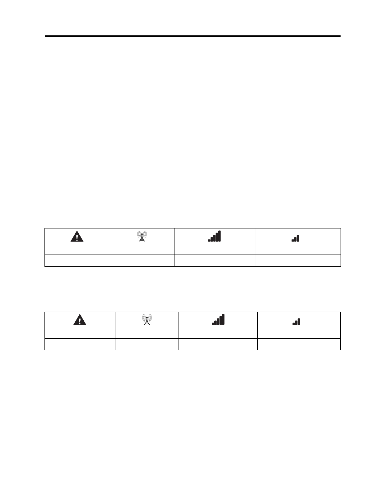
Step 2a – SIM Card is Activated.
The red LED will be on solid, the blue LED will be off and the signal strength LEDs will display the average signal strength. In this
state, the LE4000 is registered to the cellular network.
Red Blue Blue/Green (Top) Blue/Green (Bott om)
ON OFF - -
If the signal strength is too low (bottom signal LED off or flashing), the LE4000 will move to Step 3 and scan for carriers with suf-
ficient signal strength and attach to the carrier. If the LE4000 is connected to a carrier with sufficient signal strength (minimum of bot-
tom signal strength LED on solid), it will move to Step 4.
Step 2b – SIM Card is Not Activated
The red LED will flash, the blue LED will be off and the signal strength LEDs will display the average signal strength.
Red Blue Blue/Green (Top) Blue/Green (Bott om)
FLASHING OFF - -
In this state, the LE4000 is unable to register to the cellular network because it is inactive. The signal strength indicated is from any
nearby cell tower (including cellular towers belonging to non-roaming partners) and does not necessarily reflect the signal strength of
the intended network. The LE4000 will remain in this state until the SIM is activated. Once the SIM is activated, the LE4000 will
move to Step 2a.
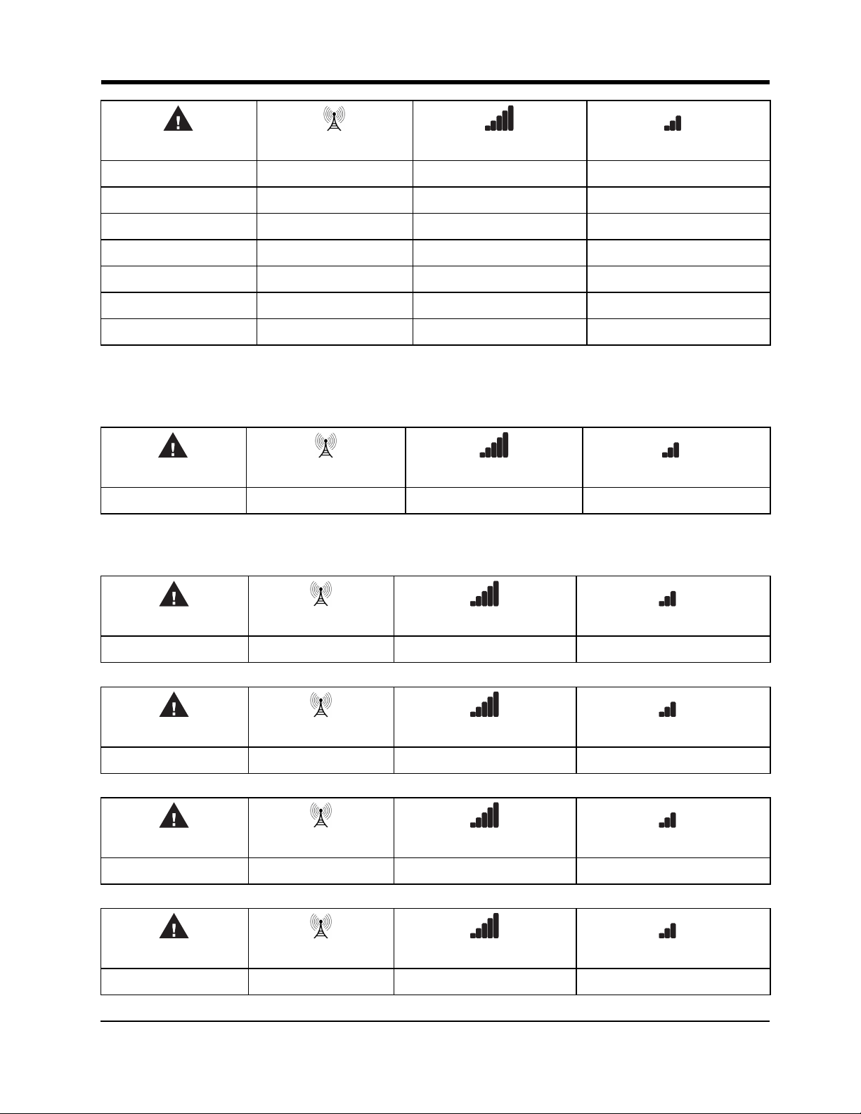
Step 3 – Carrier Scanning Due To Insufficient Signal Strength
The LE4000 will scan the surrounding cellular network and connect to the carrier to provide a signal strength of at least 7 CSQ. When
this action is being performed, all four LEDs will activate to show a scanning sequence. The LEDs will cycle from top to bottom and
then bottom to top. This cycle will continue until the LE4000 is connected to a carrier with a signal strength above 7 CSQ (minimum
of bottom signal strength LED on solid). This process can take several minutes.
The carrier scanning sequence repeats until complete.
7
LE4000 Installation Manual
Red Blue Blue/Green (Top) Blue/Green (Bott om)
FLASH ON OFF OFF OFF
OFF FLASH ON OFF OFF
OFF OFF FLASH ON OFF
OFF OFF OFF F LASH ON
OFF OFF FLASH ON OFF
OFF FLASH ON OFF OFF
FLASH ON OFF OFF OFF
Once this is completed, the LE4000 will move to Step 4.
Step 4 - Acquire C24 Communications Programming
The red LED will be on solid and the blue LED will flash. The flashing of the blue LED indicates that the LE4000 has requested pro-
gramming from C24 Communications and is waiting for a response.
Red Blu e Blue/Green (Top) Blue/Green (Bott om)
ON FLASHING - -
Once remote programming is completed, the blue LED will switch to solid and the LE4000 will move to Step 5.
Step 5 – Receiver Initialization
The red LED and the blue LED are both solid and the signal strength LEDs are off.
Red Blue Blue/Green (Top) Blue/Green (Bott om)
ON ON OFF OFF
When the LE4000 sends a request to communicate with the central station, the top signal strength LED will begin flashing.
Red Blue Blue/Green (Top) Blue/Green (Bott om)
ON ON FLASHING OFF
When the central station communicates back with the LE4000, the top signal strength LED will turn on solid.
Red Blue Blue/Green (Top) Blue/Green (Bott om)
ON ON ON OFF
When the LE4000 sends a request to communicate with the next central station, the bottom signal strength LED will begin flashing.
Red Blue Blue/Green (Top) Blue/Green (Bott om)
ON ON ON FLASHING
8
Section 3: Installing the LE4000
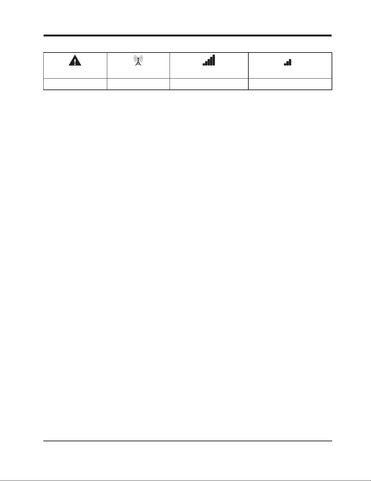
When a signal is reveived back from the central station, The bottom signal strength LED turns on solid.
Red Blue Blue/Green (Top) Blue/Green (Bott om)
ON ON ON ON
If at least one of the central stations did not respond back to the communicator, the signal strength LED corresponding to that central
station will turn off. Once the initialization sequence is complete, the LE4000 will move on to steady state operation.
Step 6 - Mount the LE4000
Note: If using an LE4000 trim plate, snap the LE4000 back plate onto the trim plate before mounting to the wall. If flush mounting or
using with an extension antenna, remove the provided breakaway from the trim plate prior to mounting.
1. Using the mounting holes on the LE4000 backplate, mark the four screw locations. Drill the anchor screw holes. NOTE:
Check for cable conduits and water pipes before drilling.
2. Inspect the mounting surface. Ensure that the surface is flat and will hold the wall tamper closed when mounted. Using anchor
screws (not provided), mount the cabinet to the wall.
3. Run the cables through the cable entry [13] or through the cabinet cable run knockout [15].
4. Complete the connections on the terminal blocks [12].
5. Reattach the front cover [1] securely to the cabinet.
Note: Refer to the wiring diagram at the end of this manual.
9
 Loading...