

Tyco Safety Canada 16WS4933 User Manual

WS4933 (433MHz) Series Wireless Carbon Monixide Detector
Installation and Operating Instructions
Read these instructions thoroughly before installation and use of the WS4933
The WS4933 is designed to monitor the CO gas level
in residential dwellings and give early warning before
potentially dangerous levels are detected. This device
is intended for use with a compatible wireless alarm
system.
The detector consists of an electrochemical carbon
monoxide sensor assembly coupled to a wireless transmitter. The Wireless Carbon Monoxide Alarm communicates with the control panel and can send alarm,
tamper and batter y condition messages to the system’s
receiver.
Caution: The detector expiry date is stamped on the
detector. Af ter the expiry date, the detector should
not be used - do not wait for end-of-life indication!
This carbon monoxide detector is designed for indoor
use only. Do not expose to r ain or moisture. Do not
knock or drop the detector. Do not open or tamper
with the detector as this could cause malf unction. The
detector will not protect against the r isk of carbon
monoxide poisoning if not properly installed.
CAUTION: This device will only indicate the presence of carbon monoxide gas at the sensor. Carbon
monoxide gas may be present in other areas. This carbon monoxide alarming device is designed to detect
carbon monoxide gas from ANY source of combustion. It is NOT designed to detect smoke, fire or
other gases unless the product has been investigated
and determined to comply with applicable requirements.
Figure 1: WS4933 Wireless CO Detector
Legend
A. Alar m L ED (see Table 1 f or LED indications)
B. Test/Hush button
C. Battery compartment
CAUTION: Unauthorized removal of the unit
from the bracket will initiate a tamper alert.
Warnings:
The WS4933 Series wireless Carbon Monoxide
detector shall be installed and used within an environment that provides the pollution degree max 2 and
overvoltages category I I in NON HAZARDOUS
LOCATIONS, indoor only. The equipment is
designed to be installed by SERVICE PERSONS
only; (SERVI CE PERSON is defined as a person having the appropriate technical training and experience
necessary to be aware of hazar ds to which that person may be exposed in performing a task and of measures to minimize the risks to that person or other
persons.)
Failure to properly install, test and maintain a CO
detector may cause it to fail, resulting in loss of life.
Installation of the CO detector should not be used as a
substitute for proper installation, use and maintenance
of fuel burning appliances, including appropriate ventilation and exhaust systems.
Installation Instructions
Battery Installation
To replace the battery:
1. Remove the detector from its mounting base by
twisting it counterclockwise. Remove and dispose of the battery according to your local regulations.
2. To ensure proper power-down sequence, wait a
minimum of 20 seconds before installing the
new battery.
3. Install a new 3-volt CR123A Panasonic Lithium
battery in the battery compartment observing
correct polarity. If the battery is incorrectly
inserted, remove gently with a non-conductive
tool and correctly reinsert.
4. Reinstall the detector onto the mounting base by
turning it clockwise.
5. After the power-up sequence, the green LED
should blink once every 12 seconds to indicate
normal operation. If the battery is not installed
correctly, the detector will not operate and the
battery may be damaged.
Enrollment
At the alarm control panel, program the 6-digit serial
number of the WS4933 (located on the back of the
detector). Please ref er to your control panel installation manual for details.
Selecting a Location
Selecting a suitable location is critical for the CO
detector. The Consumer Product Saf ety Commission
(CPSC) recommends to use at least one CO detector
per household, located as near as possible to sleeping
areas of the home, because the human body is most
vulnerable to the CO gas ef fect during sleeping hours.
1
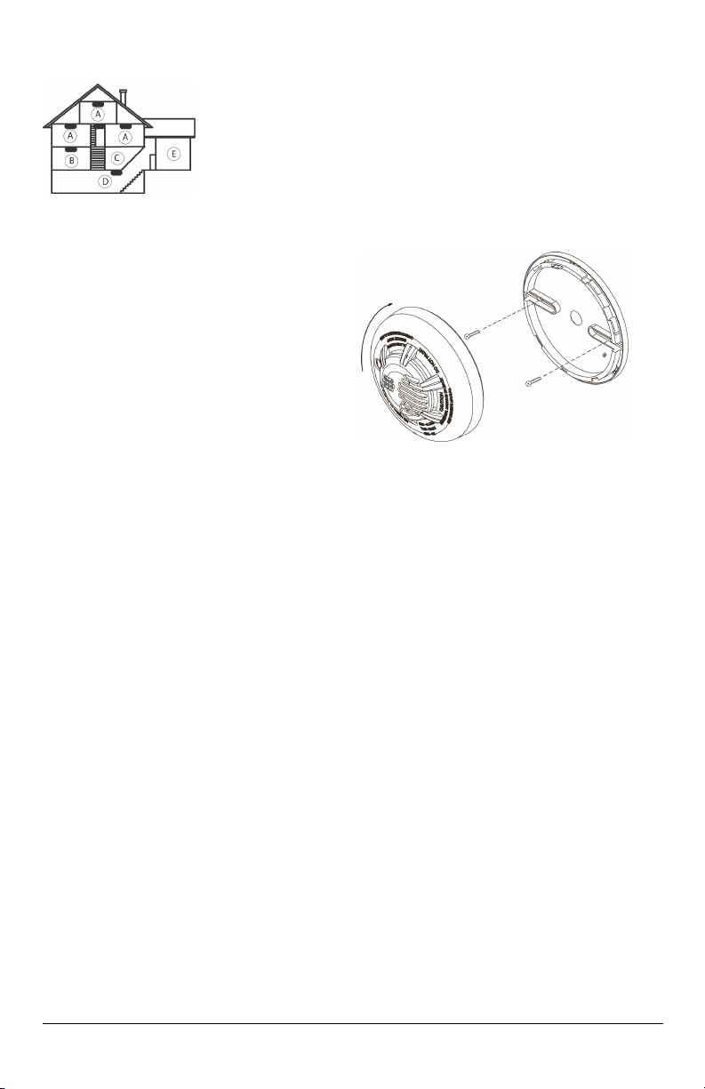
Figure 2: CO Detector Placement
Legend
A: Bedroom
B: Living Room
C: Kitchen
D: Basement
E: Garage
For added protection, install additional CO detectors in every separate bedroom and on every level of
your home. If your bedroom hallway is longer than
14 meters (40 feet), install a CO detector at BOTH
ends of the hallway. Install an additional detector 6
meters (20 feet) away from the furnace or fuel
burning heat source.
For maximum protection, the detector should also
be located outside primary sleeping areas or at each
level of your home. Mount the detector on a firm
wall or ceiling.
DO NOT install CO detectors:
l In locations where temperature may be below
0ºC (14ºF) or above 40ºC (104ºF).
l In locations where humidity is below 10% or
above 93% RH non-condensing.
l Near paint thinner fumes.
l Near air conditioners, furnaces, stoves, fire-
places and any other ventilation source that may
interfere with CO gas enter ing the detector.
l In locations where furniture or draperies may
obstruct the air flow.
l In exhaust streams f rom gas engines, vents,
flues or chimneys.
l Where dirt or dust could collect and block the
sensor and prevent it f rom working.
l In locations that can be reached by children.
l In turbulent air from ceiling fans.
l In close proximity to an automobile exhaust pipe
- this will damage the detector.
Mounting
The detector can be mounted on a wall or ceiling.
For EN approved sites, only ceiling installation is
allowed.
The WS4933 must be mounted with its bracket
(when it is attached to its bracket the tamper switch
is pressed and the detector automatic reset is performed).
1. Refer to the diagram below and install using
screw locations as required. Maneuver the
base so the screws are at the elbow of the
screw slots and secure.
2. Fit the detector inside the mounting bracket by
aligning it as shown in Figure 3 (detector’s
alignment notch should be slightly off set from
the mounting bracket tamper release tab), then
turn the detector in a clockwise direction until
it clicks into place.
3. Test the detector after completing the installation (as described in the TESTING THE
DET ECTOR section of this manual) and
refer to the alarm control panel installation
manual for additional information concerning
the use of wireless devices.
Figure 3: Mounting the Detector
Tamper Protection
The WS4933 includes a tamper resistant feature
that prevents removal from the mounting base
without the use of a tool. To engage the tamper resistant feature, cut the small plastic tab located on
the mounting bracket and then install the detector.
To remove the detector f rom the base once it has
been made tamper resistant, use an appropriate
screwdriver to depress the square tamper release
tab located on the skirt of the mounting bracket and
turn the detector counterclockwise.
Owner's Instructions
Testing the Detector
Note: Before testing, notify the central station.
Test the detector by pressing the Test/Hush button.
The red LED flashes and the sounder emits a temporal 4 pattern. T he keypad indicates that the
detector is in alarm.
Maintenance
Press the detector's TEST/Hush button once ever y
week to ensure proper operation of the detector.
When low battery alarm exists (see specifications)
immediately replace the battery.
Once a month, use a vacuum cleaner to keep the air
vents free of dust.
2

Audible and Visual Indications
The tricolored LED (green, yellow, red) and a
sounder on the detector provide local visual and audible indication of the detector’s status as listed in
Table 1.
Sounder (does
not pulse the
Status LEDs
Green
Normal
Alarm/Test
Detector
Trouble
Low
Battery
Detector
End of
Life
Powerup
Tamper
Table 1: Detector Status and Indication
flash
every 12
seconds
Red f lash
every 12
seconds
Yellow
flash
every 6
seconds
Yellow
flash
every 12
seconds
Yellow
flash
every 23
seconds
Green,
yellow,
red flash
sequence
every 12
seconds
Green,
yellow,
red flash
sequence
every 12
seconds
sounder and
LED con-
currently)
Off
ANSI S3.41
temporal 4
(press button
to hush for 5
minutes)
One 100ms
chirp every 45
seconds
One 100ms
chirp every 45
seconds (press
button to hush
for 12 hours)
One 100ms
chirp every 45
seconds
One 100ms
chirp at end
of power-up
sequence
Off Tamper
Radio Sig-
nalling
Normal
(none)
Alarm
Fault
Low
battery
Fault
None
Specifications
End of life:
Operating
frequency:
Audible
signal (temp
4 tone):
Operating
current:
Temperature
range:
Operating
humidity
range:
Transmitted
messages:
Power
source:
Battery
supervision:
Battery life
expectancy:
Low battery
threshold:
7 year s (see date stamped on back
of detector)
433MHz
85 dBA min. in alarm (at 10ft
(3m))
10 μA
0°C to 40°C (32°F to 104°F)
15% to 95% Relative Humidity,
non-condensing
CO gas alarm, low battery, tamper,
trouble message as a result of
sensor end of life or sensor trouble,
supervision.
One 3-volt CR123A Panasonic
Lithium Battery (included)
Automatic transmission of battery
status data as part of any
transmitted message.
5 year s (under typical use). Note:
Constant exposure to temperature
or humidity extremes may r educe
battery life.
2.3 V
You should know about Carbon Monoxide.
Carbon monoxide, also known as "CO" by the chemical form, is considered to be a highly dangerous
poisonous gas, because it is colorless, odorless or
tasteless and very toxic. In general, biochemistry
phenomena have shown that the presence of CO gas
inhibits the blood's capacity to transport oxygen
throughout the body, which can eventually lead to
brain damage. I n any enclosed space (home, office)
even a small accumulation of CO gas can be quite
dangerous. Although many products of combustion
can cause discomfort and adverse health ef fects, it
is CO gas which presents the greatest threat to lif e.
Carbon monoxide is produced by the incomplete
combustion of fuels such as natural gas, propane,
3
 Loading...