

Tyco Safety Canada 163G4005 User Manual

4005 Series
Universal Cellular Communicator
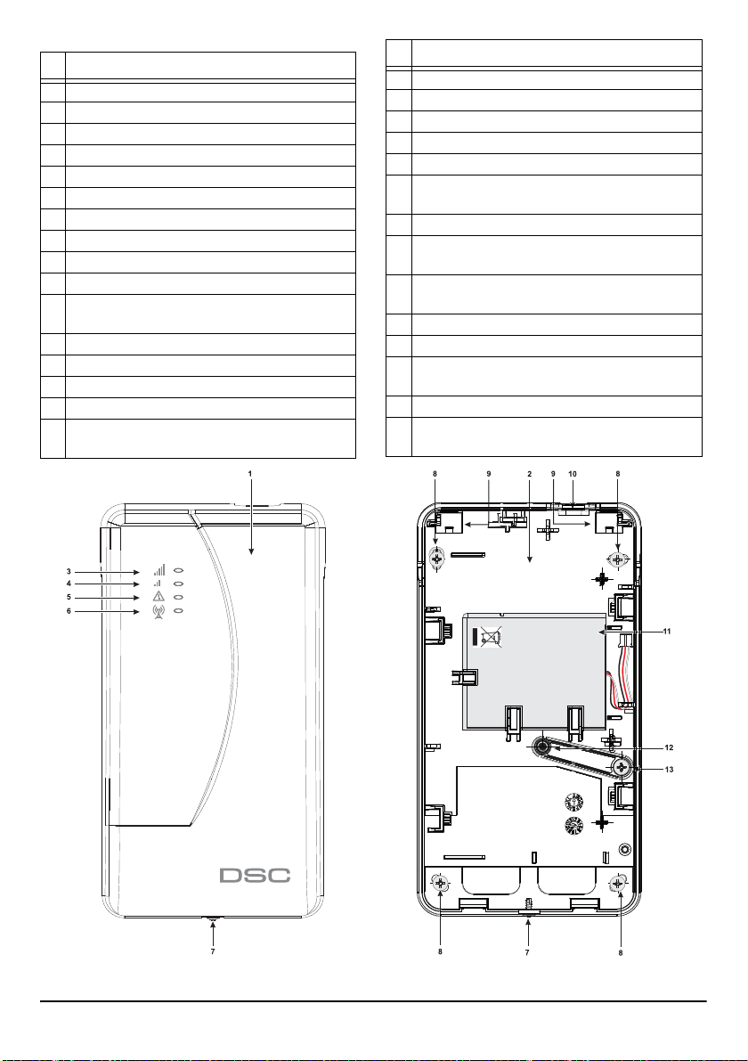
N. Parts
1Cover
2Backplate
3 LED max. GSM reception
4 LED min. GSM reception
5 Trouble LED
6 GSM connection LED
7 Fixing screw (provided in the side position 7, Figure2)
8 GSM antenna
9 Hinges for closing cover
10 Antenna cable hole
11 2700mAh rechargeable battery (accessory Item): only
GS4005, 3G4005/AM and 3G4005/EU
12 Antitamper device
13 Fixing screw for antitamper device
14 SIM-Card port
15 PC-LINK connector
16 Jumpers PST, USB, TMP, UFC: see par. “Jumper
Description” on page 7
N. Parts
17 USB port: only GS4005, 3G4005/AM and 3G4005/EU
18 Antitamper contact
19 Terminal boards
20 Positioning pins for PCB mounting
21 Jumper 1: see par. “Jumper Description” on page7
22 Battery connector: only GS4005, 3G4005/AM and
3G4005/EU
23 Cable adapter for GSM antenna
24 Nut and washer to secure the cable adapter for GSM
antenna
25 Integrated antenna: only GS4005, 3G4005/AM and
3G4005/EU
26 Hole for antenna cable on the metal bracket
27 Wall bracket
28 ANT5-02, GSM antenna with 2 m cable and SMA con-
nector (accessory item)
29 GSM antenna with 2 m cable and MMC connector
30 Adhesive plastic support: only GS4005-K, 3G4005-K/
AM and 3G4005-K/EU
Figure 1 – Box parts (only GS4005, 3G4005/AM and 3G4005/EU).
2 Universal Cellular Communicator
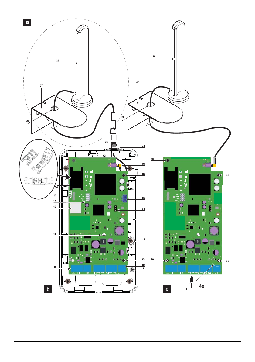
Figure 2 – Parts identifications: a) ANT5-02, GSM antenna with 2 m cable and SMA connector (accessory item); b) GS4005,
3G4005/AM and 3G4005/EU; c) GS4005-K, 3G4005-K/AM and 3G4005-K/EU.
4005 Series 3

INTRODUCTION 5
General description . . . . . . . . . . . . . . . . . . . . .7
Status LEDs . . . . . . . . . . . . . . . . . . . . . . . . . .11
Terminals description . . . . . . . . . . . . . . . . . . 13
Connection example . . . . . . . . . . . . . . . . . . .14
USB Functionality . . . . . . . . . . . . . . . . . . . . .15
Power Monitor . . . . . . . . . . . . . . . . . . . . . . . .16
Operating Principles . . . . . . . . . . . . . . . . . . .17
Event Priority management. . . . . . . . . . . . . .19
Internal events . . . . . . . . . . . . . . . . . . . . . . . . 20
Pay As You Go Balance. . . . . . . . . . . . . . . . .20
Panel Transmission Monitoring (PTM). . . . .21
Activating the Outputs. . . . . . . . . . . . . . . . . .21
Remote Programming by SMS Messages . .24
PC PROGRAMMING 27
Phonebook . . . . . . . . . . . . . . . . . . . . . . . . . . .30
Options . . . . . . . . . . . . . . . . . . . . . . . . . . . . . .31
Network Setting . . . . . . . . . . . . . . . . . . . . . . .33
Input/output. . . . . . . . . . . . . . . . . . . . . . . . . . .34
Communicator . . . . . . . . . . . . . . . . . . . . . . . .35
IP Receivers . . . . . . . . . . . . . . . . . . . . . . . . . .38
Voice Message . . . . . . . . . . . . . . . . . . . . . . . .39
PSTN/PTM . . . . . . . . . . . . . . . . . . . . . . . . . . . .40
Event Log . . . . . . . . . . . . . . . . . . . . . . . . . . . .41
Firmware update. . . . . . . . . . . . . . . . . . . . . . .42
Status. . . . . . . . . . . . . . . . . . . . . . . . . . . . . . . .42
APPENDIX 43
EN 50136-2: 2013 compliance . . . . . . . . . . . .43
Pass-Through . . . . . . . . . . . . . . . . . . . . . . . . .4 5
Hereby, Digital Security Controls declares that the
is in compliance with the essential requirements and other relevant provisions of Directive 1999/5/EC. The complete R&TTE Declaration of
The GS4005, GS4005-K, 3G4005/AM, 3G4005/EU, 3G4005-K/AM and 3G4005-K/EU product models have been certified by IMQ/A to be compliant with
EN 50136-1:2012 and EN 50136 2:2013 for Alarm transmission system performance SP2 (D2, M2, T2, S0, I0) for vocal/SMS alarm messages and SP4 (D3,
Installation of these systems must be carried out strictly in accordance with the instructions described in this manual, and in compliance with the
Digital Security Controls shall not be responsible for damage arising from improper installation or maintenance by unauthorized personnel.
Digital Security Controls recommends that customers dispose of their used equipment (panels, detectors, sirens, and other devices) in an environmentally
sound manner. Potential methods include reuse of parts or whole products and recycling of products, components, and/or materials. For specific information
In the European Union, this label indicates that this product should NOT be disposed of with household waste. It should be deposited at an
4 Universal Cellular Communicator
The communicator is certified IMQ-SECURITY SYSTEM if powered by the panel and without battery backup.
local laws and bylaws in force. The above mentioned devices have been designed and made to the highest standards of
quality and performance. The manufacturer recommends that the installed system should be completely tested at least once a month.
Digital Security Controls reserves the right to change the technical specifications of this product without prior notice.
appropriate facility to enable recovery and recycling. For specific information see http://www.dsc.com
To program this device use the DLS 5 console software ver. 1.50 or higher.
Conformity for each Device can be found at www.dsc.com.
Waste Electrical and Electronic Equipment (WEEE) Directive
4005 Series
M3, T4, S2, I3) for digital messages.
Recycling information
see http://www.dsc.com.

INTRODUCTION
Devices in the 4005 Series are GSM communicators which, in the absence of a PSTN line, transmits vocal and digital alarms to
System III or System II receivers, via GPRS GPRS Quad-Band (HSPA Dual-Band). The following models are available.
GS4005: communicator with 2G module in the plastic cabinet.
3G4005/AM: communicator with 850/1900 MHz 3G module, in the plastic cabinet.
3G4005/EU: communicator with 900/1800MHz 3G module, in the plastic cabinet.
GS4005-K: kit including communicator with 2G module, antenna with 2 m cable, adapter and metal bracket.
3G4005-K/AM: kit including communicator with 850/1900 MHz 3G module, antenna with 2m cable, adapter and metal
bracket.
3G4005-K/EU: kit including communicator with 900/1800 MHz 3G module, antenna with 2m cable, adapter and metal
bracket.
All information relating to a specific model shall be attested to by referenc e to the correspo nding code . The word “Communicat or” is
being used to describe functions which are common to the various models. This manual provides programmin g and operation of the
Communicator. If there are any special installation requirements a remote outside antenna (ANT5-15) with 15 m cable is available.
This Communicator is fixed and shall be installed by Service Persons only (service person is defined as a person having the
appropriate technical training and experience necessary to be aware of hazards to which that person may be exposed in
performing a task and of measures to minimize the risks to that person or other persons). It shall be installed and used within
an environment that provides the pollution degree max 2, over voltages category II, in non-hazardous, indoor locations only.
This manual shall be used with the Installation Manual of the alarm control panel.
General Features
Simulates land line
Switches automatically to GSM Network in the event of
land line trouble (line down)
Manages and signals Incoming/Outgoing call
GSM signal indicato r
6 programmable terminals as Open Collector Outputs or
Input Lines
Land line overvoltage protection
GSM Quad-Band (HSPA dual-band) o 3G Cellular Com-
municator
Integrated Antenna on Board or external Antenna with
magnetic base: kit including communicator with 850/1900
MHz 3G module, antenna with 2m cable, adapter and
metal bracket.
SMS Dialer
Voice Dialer
Supports Contact ID communication format from a connected control panel for communication over the GPRS
network
GPRS/Internet communication with receivers Sur-Gard
System III / II
PC-programmable options
32 SMS messages, each with a maximum length of 100
characters (2 for each Input Line plus 6 for Status Indications and 1 Periodic)
8 telephone numbers (max. 16 digits) programmable for
the SMS dialer
8 phone numbers programmable for Contact ID Dialer on
GPRS
Up to 32 telephone numbers (max.16 digits) programma-
ble for the remote activation of the OC output
Remote activation of the outputs through caller identifica-
tion and/or SMS transmission
Credit balance check for pre-paid SIM Cards
Panel Transmission Monitoring (PTM)
Integrated tamper switches
PC-LINK connector
USB type A connector (Host and Device)
Programming through USB memory stick
Advanced Diagnostic and LOG recording
Local and remote programming and FW upgrade
Alarm event transmission over GSM/GPRS/HSPA
Programmable priority between PSTN/Cellular
Two way voice communication on the cellular
Optional backup battery
Anti-jamming
4005 Series 5
Technical Specifications
The supply voltage for this communicator is provided by the Control panel connected (10.7 V to 27.6 V) or from an external power
supply that provides the 12V and recharging, if necessary, a back-up battery (accessory item). The only purpose of the battery is
to provide the power in the event the primary power source is lost. The required autonomy in stand-by is 8 hours.
In both cases, if the main power is lost the battery assures that the panel will still powered and working.
The main power voltage and the battery voltage will be supervised.
The power supply for the Communicator models GS4005, 3G4005/AM and 3G4005/EU shall be:
SELV type;
Limited power;
Limited to 1 A.
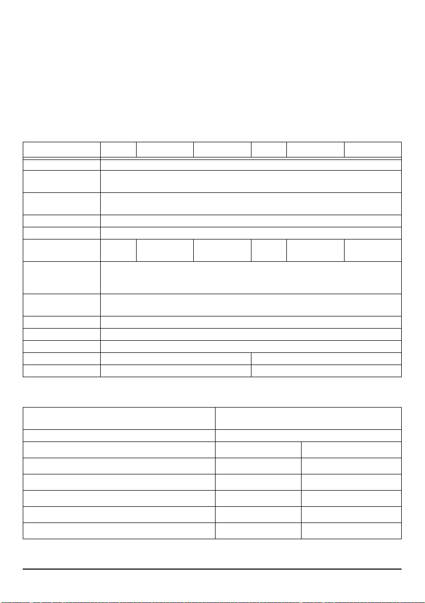
Model GS4005-K 3G4005-K/AM 3G4005-K/EU GS4005 3G4005/AM 3G4005/EU
Input Voltage 10.7 to 27.6 V_
Standby average cur-
rent, without battery
Maximum current drawn
in current limited mode
Maximum current drawn 450 mA (not including outputs) @ 13,8 V_
Outputs 6 open-collector, 100 mA
Operating frequency
(MHz)
Maximum loop resistance
of line between the device
connected in series on LI
Maximum number of parallel devices connected on LI
Environmental class II
Operating Temperature -10 to +40 °C
Humidity 0 to 95%
Dimensions (WxHxD) 76x151x20 mm (PCB only) 101x186x41 mm
Weight 66 g 250 g
Table 1: Technical specifications.
900/1800
850/1900
GSM: 850/1900
UMTS: 850/1900
90 mA (not including outputs) @ 13,8 V_
230 mA (not including outputs) @ 13,8 V_
GSM: 900/1800
UMTS: 900/2100
900/1800
850/1900
1 Kohm
1
GSM: 850/1900
UMTS: 850/1900
GSM: 900/1800
UMTS: 900/2100
Interface type between SPT (Supervised Premises Transceiv er)
and AS (Alarm System)
ATS (Alarm Transmission System) SINGLE PATH
Alarm Transmission System performan ces SP4 for digital messages SP2 for vocal/text messages
Average transmission time
Maximum transmission time
Reporting time
Substitution security
Information security
Table 2: EN 50136-1:2012 e EN 50136-2:2013 specifications.
6 Universal Cellular Communicator
D3 (20 s) D2 (60 s)
M3 (60 s) M2 (120 s)
T4 (180 s) T2 (25 h)
Proprietary interface
S2 S0
I3 I0

Jumpers Description
See Figure 2 on page 3.
Jumper 21
j pins 1 and 2 connected, no input current limit (default);
k pins 2 and 3 connected, input current limit (450 mA, from battery charger side).
PST (Pass-Through)
J open, Pass-Through disabled (default);
K closed, the communicator will be able to perform remote programming of the PC 1864 4.1 EU, PC 1864 4.2 EU, PC 1864 4.2
ADT Spain and PC 1864 4.5 ADT Spain DSC Power Series intrusion panels, via cellular and PC-Link.
USB
The communicator, according to the jumper setting, from the USB point of view may be Host or Device:
J open, Device role (default);
K closed, Host role (see page15).
TMP (Tamper):
J open, tamper detected (default);
K closed, tamper not detected.
UFC
Future Use
General description
This Communicator manages SMS and Central Station transmissions and can simulate the land line in the event of trouble (land
line down) or even substitute the land line completely in areas where the GSM service is provided and where the land line is not
available. It has capability of communicating alarm signals via the GPRS data network. This capability enables a fast reliable path
to central stations equipped with a Sur-Gard System III or System II receiver.
The performance of this Communicator depends greatly on GSM Network coverage, therefore, it should not be mounted without
first performing placement tests of th e antenna to determine the best loca tion f or recept ion (at le ast the LED should remain lit).
The communicator has 6 T terminals that can be programmed as follows:
– Outputs (default setting) which can be activated/deactivated remotely, or used to provide status indications (problems on the
PSTN telephone line; problems on the GSM network; Supervision Message Missing; Fail To Communicate FTC), IP receiver fault,
Power fault, Tampers, Jamming detect, Antenna fault, Reserved output.
– Input: Panel interconnection Presence: used to be c onnected with a panel, Voice dialler: use d to trigger a voice dialler event, SMS
dialler: used to trigger a SMS dialler event, Dialler Block: used to stop the dialler and delete the queue, Force Communication On
GSM: force the line switch from LE to LI, Internal CID/SIA: used to generate the internal CID/SIA event. This Communicator can
activate only as intended and cannot be used as a modem for fax/data transmissions or for teleservice operations.
Parts Identification
The numbers in square brackets [ ] in this manual refer to the main parts of this Communicator (see Figure1 and 2, and relative
table on page 2).
4005 Series 7

GS4005-K, 3G4005-K/AM and 3G4005-K/EU mounting
This Communicator shall b e installed by qu alified SERVICE PERSONS only, in the shelte r of a safe and dry site, away from radiotransmitting equipment
Test the GSM Network reception before mounting this Communicator in the proposed placement.
Do not route any wiring over circuit boards.
The length of the power cables cannot exceed 3 meters.
This Communicator consists of a board intended to be placed inside the intrusion panel, preferably having a metal cabinet, and of an
antenna that is connected to the board by a coaxial cab le. Duri ng norm al work ing, those eleme nts (boar d, anten na and cable) cou ld
generate radiated electromagnetic fields and, if there are a ny electronic d evices not sufficiently immu ne to such fields nearby , there
might occur certain unwanted interactions. For this reason it is advised to place the board as far away as possible from such susceptible
devices and to put the antenna on the external s urfa ce of the metal cabinet or far away from it by means of the bracket. It is advised
to keep inside of the panel metal cabinet the minimum coaxial cable part and to place any extra length on the outside of the metal box.
1. Loosen the screws and remove the control panel cover.
2. Establish an area inside the metal casing which can be used to hold the board, including the wiring.
3. Positi on the 4 adhesive plastic supports on the base of the metal base, then f it the holes [30] on the Electronic board into the
adhesive plastic supports, as illustrated in Figure 3.
4. Fix the antenna with the 2 m c able
joint with the surface. Feed the antenna cable through the cable feed opening in the metal cabinet.
It is possible to use the metal support [27], see Figure2. Fix the metal support [27] by using the holes [26] on an adequate
prop. Fix the antenna with the 2 m cable above the metal support [27] (Figure 3), in such manner that the magnetic base will
be conjoint with the surface. Pass the antenna lead through the hole [26] in the metal support [27].
5. Connect the cable to the GSM antenna connector [23].
6. Complete the connections on the terminal boards [19].
7. Close the jumper TMP to disable the tamper detection.
8. Insert the SIM-CARD face down in the SIM holder [14] (see Figure2).
.
[29]
above the metal cabinet (Figure3) in such manner that the magnetic base will be con-
The SIM-CARD PIN must be disabled before the card is inserted into the Communicator.
It is recommended that you disable call forwarding on your SIM card.
9. Make sure that the Line Status (Yellow) and System Fault (Red) LEDs flash when the Communicator is switched on: this indicates that the Communicator is in its start-up phase.
10. Che ck signal strength:
make sure that at least the LED remains lit; the LED lit indicates optimal coverage;
if the LEDs and are OFF, the signal strength is TOO WEAK: for the signal to be of an acceptable level, at least the
LED must be lit.
11. Close the cover of the control panel on the base using the suitable screws.
Connect power circuit and the telephone line only after the cabinet has been secured to the wall or structure and has been
connected to the protective earth ground of the building.
Before inserting or removing the SIM card, please ensure the device is powered down.
ANT5-15 Remote Antenna
For details of how to fit the remote ANT5-15 outdoor an tenna (15m cable length with adapter) please refer to the instructions supplied with the product. The ANT5-15 is used to provide the Communicator a excellent GSM signal strength (see Figure3).
8 Universal Cellular Communicator
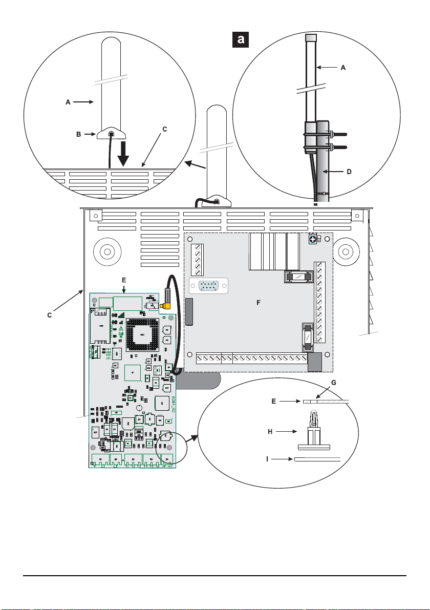
Figure 3 –
4005 Series 9
GS4005-K, 3G4005-K/AM and 3G4005-K/EU
Communicator board; F) main board control panel; G) board hole; H) four adhesive plastic supports; I)metal box
base.
Mounting: A) antenna; B) magnetic base; C) metal box; D) support; E)

GS4005, 3G4005/AM and 3G4005/EU mounting
See Figures1 and 2.
1. Mark the posit ion of the holes [8] required to fix the plastic base [2] and the antitamper device [13] to the wall.
2. Drill holes in the wall as marked.
! Make sure you do not damage wiring or pipes in the chase.
3. Insert the 5 sup ports into the holes on the wall.
4. Feed the connection cables through the opening on the base.
5. Fix the plasti c base to the wall using wall anchors (not supplied).
6. Insert the silicon carbon pills for antitamper on the dedicated support on the base [12].
7. Insert the back-up battery (accessory item).
8. Place the electronic board on the supports [20] and push it down until it clicks into place.
Read the following steps (9, 10 and 11) if the signal with the integrated a ntenna is low, to mount the ANT5-02 external opt ional
antenna, else go to step 12.
9. Connect the ant enna cab le [23] to th e conn ector on t he electr onic board and f ix other conn ector of the ca ble to the communicator backplate with the nut and washer [24] (into dedicated hole).
10. Connect the magnetic antenna cable, using the SMA connector.
11. Position the antenna [28] on the upper edge of the base.
The antenna will be positioned on the point most suited to receiving the GSM signal.
12. Complete the connections on the terminal boards [19].
The length of the power cables cannot exceed 3 meters.
13. Insert the SIM-CARD face down in the SIM holder [14].
! The SIM-CARD PIN must be disabled before the card is inserted into the Communicator.
It is recommended that you disable call forwarding on your SIM card.
14. Make sure that the Line Status (Yellow) and System Fault (Red) LEDs flash when the Communicator is switched on: this indicates that the Communicator is in its initialization phase.
15. Check signal strength:
make sure that at least the LED remains lit; the LED lit indicates optimal coverage;
if the LEDs and are OFF, the signal strength is TOO WEAK; for the signal to be of an acceptable level, at least the
LED must be lit.
16. Close the Communicator cabinet: fasten the upper side of the cover [1] to the backplate [2], using the hinges [9] and then fix the cover using the screw [7], that you can find on the backplate.
Connect power circuit and the telephone line only after the cabinet has been secured to the wall and has been connected to
the protective earth ground of the building.
Before inserting or removing the SIM card, please ensure the device is powered down.
Tamper detection
The activation of tamper switch (optional) allows you to detect the Communicator cover opens or the removal of the device from
the wall (see “Jumpers Description > TMP”).
For the opening of the communicator cover or the removal of the communicator from the w all, will activate the s end of an SMS and/
or voice message to one or more phone numbers, or an out put will be ac tivate d, it is necessa ry, b y the DLS 5 Cons ole, to program
the Communicator (insert phone numbers at the event Tamper / Restore and in the page of Programming from PC-> Inputs /
Outputs enable an Output. After the programming, close the cover and power up the Communicator. After the initialization phase
10 Universal Cellular Communicator
of the Communicator, open the cover and check that the SMS and / or voice message is sent to the programmed telephone numbers and the output is enabled.
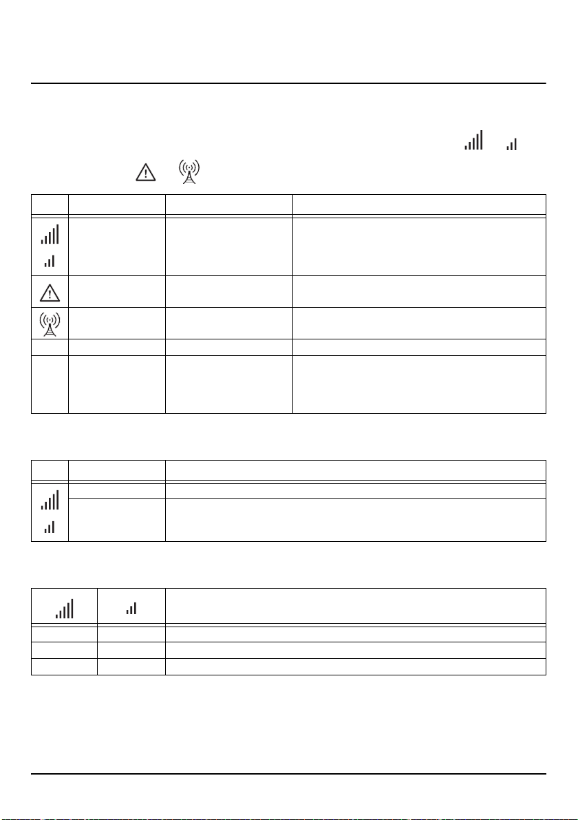
Status LEDs
There are 8 LEDs on the PCB that indicate the Communicator status.
During start-up, all LEDs will be ON less 1second. During the programming default procedure, LEDs and will be
OFF while the LEDs and will be ON.
LED Colour Name Description
Green/Yellow GSM signal strength Packet Service Network Type (see Table4).
Red Fault See Table7
Yellow Line Status ON: the communicator has switched on simulated PSTN.
G Green GSM Network Status LED for technical support.
ACT Green USB ON: HOST.
Table 3: Status LEDs.
GSM Signal Strength (see Table 5).
Communication Type (see Table6).
Slow flashing: OFF-Hook and voice message transmission.
OFF: DEVICE.
Slow flashing: error.
Fast flashing: activity.
LED Colour Packet Service Network Type
Green GPRS or EGPRS
Yellow WCDMA, HSDPA or unknown (only 3G versions)
Table 4: Packet Service Network Type.
GSM Signal Strength
OFF OFF NO GSM network available.
OFF ON GSM signal low
ON ON GSM signal High.
Table 5: GSM Signal Strength.
4005 Series 11
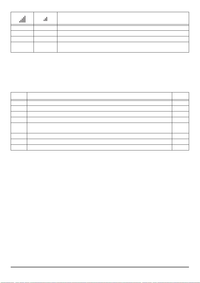
Communication Type
Slow Flashing Slow Flashing Device initialization: the LEDs flash until a GSM signal is received by the Communicator.
Fast Flashing OFF Incoming SMS: the LED flashes a few seconds.
Slow Flashing OFF Remote Session: the LED may flashes a few seconds after the end of session.
OFF Slow Flashing Voice call: it signals the voice calls of the Communicator NOT those of connected control
panel, if any.
Table 6: Com m u nication Type.
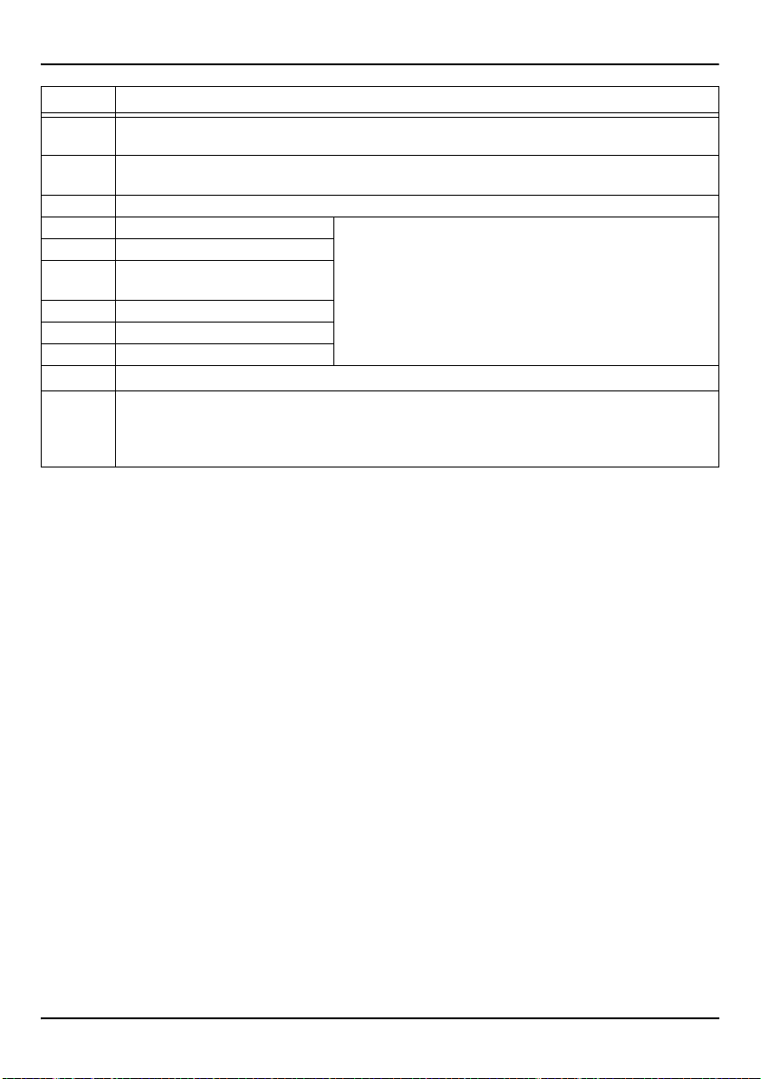
Fault LED
This LED is normally OFF. It indicates malfunctioning by flashing in the event of trouble. On power-up, the Co mmunicator checksfor
certain trouble conditions to be met shown in the Table7 below. The most significant malfunctioning status will be indicated, w ith
the corresponding number of flashes of the RED LED: see the Table 7 below for number of flashes and malfunctioning indication
priority.
Priority Description Flashes
1 (HIGH) Firmware problem (incorrect firmware): invalid data found in an external flash memory. 1
2 Power supply trouble: the supply voltage drops below 10.7V. 2
3 Battery trouble: the battery voltage drops below 3.4V. 3
4 Default PIN: the EN50136 option is enabled and User, Installer or Level 4 PIN are at default. 4
5 GSM radio fault: the microcontroller is not able to communicate with GSM radio module, during the ini-
tialization sequence.
6 SIM trouble: the SIM card has the PIN check enabled. 6
7 GSM Net work trouble: the radio is not able to connect to the GSM network. 7
8 (LOW) GPRS/HSPA trouble: the radio is not able to connect to the GPRS/HSPA network. 8
Table 7: Fault LED.
5
12 Universal Cellular Communicator
Terminals description
Terminal Description
-
LI Internal telephone line: these terminals must be connected to the control panel or an alternative communication
LE External telephone line: these terminals can be connected to the PSTN line.
T1 Default: output, PSTN fault. Programmable terminals.These terminals can be programmed as follow.
T2 Default: output, no cellular network.
T3 Default: input, interconnection pres-
T4 Default: output, tamper.
T5 Default: output, GSM fault.
T6 Default: output, Jamming.
M
+V Power supplied by the control panel, at a level between 10.7 and 27.6V_;
Ground: this terminal must be connected to the Mains Earth, in order to comply with the Telecommunications Network Safety Standards (Overvoltage Protection Requirements).
terminal.
– Open collector outputs: these outputs may be activated either by programmed events (automatic activation), or by a command sent via SMS,
ence.
Negative: Power supply and shared terminal for the Open Collector outputs.
make sure that this is protected and operating at a limited current; Limited Power Source (LPS) in
conformity with EN 60950-1:2006 standard. To connect the supply use wires with a maximum 3 m length
and 0.75 mm² cross-section. For shorter wires use suitable cross-sections.
or through caller recognition (remote activation); please refer to the
“Output activation” section for further informa tion. The maximum curren t
available at each OC output is 100mA.
– Input lines: when these inputs receive alarm s ignals, t hey can a ctiv ate
the SMS and telephone dialer functions.
4005 Series 13
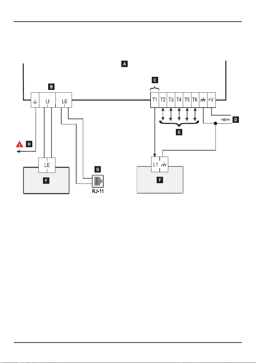
Connection example
! Incorrect connections may result in FTC fault or improper operation. Inspect wiring and ensure connections are
correct before applying power. DO NOT route any wiring over circuit boards; maintain at least 1” (24.5 mm) separation. A minimum 1/4” (6.4 mm) separation must be maintained at a ll points between Power Limited wiring and all other
Not-Power Limited wiring.
Figure 4 – Typical wiring diagram: A)4005 Series; B) disconnect telephone line prior servicing; C) example of T1 connection as
an open-collector output; D)10.7 to 27.6 V
grammed as open-collector outputs or inputs lines; F)alarm control panel; G) telephone line connection (PSTN);
H) ground connection, this connection is necessary.
14 Universal Cellular Communicator
_
power supply; E) T1, T2, T3, T4, T5 and T6 terminals may be pro-

USB Functionality
The communicator has an USB A connector. It shall be implemented a dual-role feature: may be Host or Device according to the
jumper setting: Device: J (open default), or Host K (closed) and allows the direct ins ertion of USB memory s tick (see page7
“Jumpers description”). To connect the communicator to a PC it is necessary to have an A to A USB cable (Hub cable).
The USB interface characteristics:
Compliance, USB 2.0 Specification
Data rate, Full speed (12 Mbit/s)
Max. cable length, up to 5 m
Max. current in host mode, 500mA
Vout in host mode, 5 Vnom.
File system in memory stick, FAT32.
USB Device
This interface will be a substitution for the RS232 communication (PC-Link). It will have the same functionality of the RS232, and
will be used with software console (DLS 5) to:
execute the firmware upgrade, only Installer -Level 4- is authorized;
upload/download of communicator programming and audio files, (Installer is authorized to upload/download, User can only upload);
Upload of communicator event log from the communicator by the event log page (only Installer and User are authorized);
monitoring the communicator status in real time mode only to show some information regarding the communicator. All Users
are authorized.
USB Host
This will permit to connect a USB memory stick for following features:
execute the firmware upgrade;
upload/download of communicator programming and audio files;
download of communicator event log;
download of the communicator debug log.
All this features are available only whether the EN50136 compliance is disabled.
4005 Series 15
 Loading...