

Tyco Safety Canada 15TL2553GRE User Manual

3G2055(R)-E
HSPA/3G Wireless Alarm Communicator
SCW3G Communcator - North America
TL2553G(R)-E
Ethernet/Internet and HSPA/3G Dual-Path Alarm
Communicator
SCW3G/Ethernet Communicator - NorthAmerica
Installation Manual v5.0
Warning: This manual contains information on limitations regarding product use and function and informationon the limitations as toliability of the manufacturer. Theentire manualshouldbe carefully read.

WARNING: Installer please read carefully 4
General Information 5
Keypad Data Display 5
Entering Data From Keypad 5
Entering ASCIICharacters 5
Mounting Considerations 5
Communicator Technical Specifications 6
General Information 6
Features 6
UL/ULC Installation Requirements 6
Communicator Frequency Bands for North America 7
Ratings 7
Hardware Compatibility 7
Software Compatability 7
Communicator Pre Intsallation Configuration 8
Connect24™1 Account and SIMcard Activation 8
Encryption 8
Communicator Configurationwith SCW 9
Installation Location 9
Installing CAT 5 Cable (TL2553G(R)-E only) 9
INSERTING/REMOVING THE SIM CARD 10
Communicator Reset 10
Establishing a Communication Channel with the SCW Panel. 10
Initial Programming ofCommunicator and SCW 11
SMS Command and Control Functions 11
Label Programming for SMS Message 11
Communicator Placement Test 12
Ethernet/CellularProgrammingOptions 12
System Options 12
Programming Options 14
Communications Reporting Codes 16
System Test Options [026 -029] 17
Ethernet Receiver 1 Options 18
Ethernet Receiver 2 Options 19
Ethernet Options 19
Cellular Receiver 1 Options 20
Cellular Receiver 2 Options 20
Cellular Options 21
Command and Control Options 22
SMS Command and Control Functions 22
SMS Command and Control Response 23
Receiver Diagnostic Testing 25
System Information (Read Only) 25
System Reset Defaults 26
Communicator Troubleshooting 26
Communicator Troubleshooting 28
Ethernet CellularProgrammingWorksheets 30
System Options 30
Programming Options 30
2

System Test Options 30
Ethernet Receiver 1 Options 31
Ethernet Receiver 2 Options 31
Ethernet Options 31
Cellular Receiver 1 Options 31
Cellular Receiver 2 Options 31
Cellular Options 32
Command and Control Options 32
Receiver Diagnostic Testing 33
System Information (Read Only) 33
Limited Warranty 34
System Reset Defaults 34
EULA 34
Regulatory Information 35
3

WARNING: Installer please read
carefully
Note to Installers
The warningson thisp age contain vitalinformation. Asthe only individua lin contact with system users, it is the installer’s responsibility to b ring e ach item in th is
warning to the atte ntion ofa llusers of thissystem.
System Failures
Thissystemh asbe en carefu llydesigne dto be as effectivea spossible. There are
circumstances, ho wever, involving fire, burglary, o r other type sof emerge ncies
whe re it may no tprovide p rotection. Any alarm system of an ytype may b e compromised delibera telyor mayf ailto op erate as expected for a variety of reasons.
Some, but not all, ofthe reasons may be:
Acc ess by Intruders
Intrud ersmayenter t hrough an u nprotecte daccess point, circumvent a sensing
device, evade detection by moving through an area of insufficient coverage , disconne ct aw arning device, orinterfere with orprevent the proper opera tion of the
system.
Component Failure
Although every effort has be enmad eto make thissystem asreliable as possible,
the systemmayf ailto function asinte nded due to the failure ofa compone nt.
Comprom ise of Radio Frequency (Wire less) D evices
Signalsmay no t reach the receiver und er all circumstances wh ich could include
metal objectsplaced on or near the radio path ord eliberate jamming or other inad vertent radio signa linterferen ce.
Criminal Knowledge
Thissystem conta ins security featu res wh ich were known to b e effective at the
timeo fmanufacture. It is possiblefor personsw ith criminal inten tto develop technique swhich redu ceth e effectivene sso fthese features. I tisimportan tth at your
securitysystemb e reviewed periodicallyto en sureth atits features remain effectivea ndt hat it isup dated or replaced if it isfo und th atit does no tprovide the protection expected .
Failure of Re placeable Batte ries
Thissystem’s wirelesstra nsmitters have b een designed to provide several years
of batte rylife unde r normal cond itions. The expe cted bat tery life isa function of
the device environmen t,u sage ,an dtype .Ambient conditions such ash igh humidity,h igh o r low temperatu res, or large tempe ratu re fluctuations may reduce the
expecte d batte rylife. Wh ile each t ransmitting de vice has a low battery monitor
which iden tifies whe nth e batte ries nee dto be replaced, this monitor may fail to
ope rate as expe cted. Re gularte sting a nd maintena nce willkeep the system in
goo do perating condition.
Inadequate Installation
A security system must be installed properly in order to provide a dequa te protection. Every installation should be evaluate d by a security pro fessional to
ensure tha t allaccess points an da reas a re covered. L ocks and latches on window sa nd do ors must be secure and ope rate as intend ed. Window s, doo rs,
walls,ceilingsa nd other bu ilding materialsmust be of sufficient strength and construction toprovide the level ofp rote ction expected.A reevaluation mustb ed one
during and afte rany con struction activity. An evaluation by the f ireand/o r police
dep artment ishigh lyrecommend edifthis serviceisa vailable.
Inadequate Testing
Mostp roblems that wo uld prevent an a larm system from operating as intend ed
can be found by regu lar testing and maintena nce. The complete system should
be tested wee klyan d immediatelyafter a brea k-in, ana ttempted break-in, a fire,
a storm,an earth quake, an acciden t, ora ny kind of construction activityinside or
outside the p remises. The testing shou ld include a ll sensing devices, keypad s,
consoles, alarm indicating d evices, and any o ther ope rational devices that are
part of the system.
Insufficie nt Time
There may be circumstancesw hen th e system will operate as inten ded, yet the
occupan ts will n ot b e protecte d fro m an emergency due to the ir ina bility to
respon dto the warning sina timelyman ner. If the systemis remotelymonitored,
the respon se may not occurin time top rotect the occupa ntsorth eir belongings.
Motion Det ectors
Motion detecto rscan on lyd etectmotionwithinthe designate da reasasshow n in
their respective installation instructions. Th ey cann ot d iscriminate betw een
intrude rs and intend ed occupa nts. Motion detectors do not p rovide volumetric
area prote ction. Th eyha ve multiple beams of detection and motion can only be
dete cted in un obstructed a reas covered by these b eams. They canno t dete ct
motion wh ich occurs beh ind w alls, ceilings, floor, closed doors, g lass partitions,
glass doors or wind ows. Any type of ta mpering w hether intentional or un intent ionalsuch asmasking, painting, or spraying of anymaterialon the lenses, mirrors, windo ws or a ny ot her p art of the det ection system willimpair its pro per
ope ration.
Passive infrared motion detectors op erate by sensing chan ges in tempera ture.
However their effectiveness can be reduced whe n t he ambient te mperat ure
rises near or above bodytemperature orif there are inten tiona lor un inten tiona l
sources ofh eat in or near the detection area.Some of th eseh eat sources cou ld
be hea ters,radiat ors, stoves, barbe cues, fireplaces, sunlight, steam vents, lighting and soo n.
Power Failure
Con trol units, intrusion de tectors, smoke de tectors a nd many othe r security
devicesre quirean ad equate po wersup plyfor proper opera tion. If ad evice operates fromb atteries,it is possible forthe ba tteriesto fail. Even if the batteries ha ve
not failed, they must be charged , in good condition and installed co rrectly. If a
device operates o nly by AC po wer, any inte rruption , however brief, will render
that de viceinop erative whileit d oesn oth ave powe r.Powe r interrup tions of an y
length are often accompanied by voltag e fluctuations which may damage electronic equ ipment such as a security system. After a p ower interruption has
occurred, immediately cond uct acomplete systemte st to ensure that the system
ope rate sas inten ded.
Security and Insurance
Reg ardlessof itscapa bilities, an alarmsystem isn ota substitute forpro pertyo r life
insurance. Analarmsystemalso isnot a substitute forproperty owne rs, rent ers, or
othe roccupa ntsto act pruden tlyto preven tor minimize the harmful effects of an
emergen cysitua tion.
Smoke Det ector s
Smoked etectorst hat area pa rt ofthissystemmay not properlya lert occupants o f
a fire fo r an umber of rea sons, someof which follow. The smoke de tectors may
have bee nimproperly installed orpo sitioned. Smokemay not be able tore achth e
smoked etectors, such aswh en the fireis in a chimney, w alls orro ofs, or on the
othe rside of closed do ors. Smoke de tectorsmay no tde tect smokefrom fires on
ano ther levelo fth eresiden ce orb uilding.
Everyfire isd ifferen t in the a mount of smoke p rodu ced and the rate o f burning.
Smoked etectorscan not sense alltype sof fireseq uallywell.Smoke detecto rsmay
not provide timelyw arningof fires caused by carelessness orsafe tyha zards such
as smoking in bed , violent explosions, escaping gas, improper sto rage of f lammable materials, overloaded electrical circuits, children playing with match es, or
arson.
Even if the smoke dete ctor o perates as inte nded, there may be circumstances
whe nth ereis insufficient warning to allow a lloccupa ntsto escape in time to avoid
injuryor death.
Telephone Lines
If telepho nelines areu sed to transmit alarms, the ymay be out of serviceo r busy
for certainp eriods of time. Alsoa nintru dermay cutth et eleph one line ord efeat its
ope ration by more sophisticated mean swhich may be difficultto detect.
Warning Devices
Warning devices sucha s sirens, bells, horn s, or strobes may no twarn peo ple or
waken someone sleeping ift here isa ninte rvening wallordo or.If warn ing devices
are located on a differe ntlevel ofthe residen ce orp remise, then it isless likelythat
the occupan ts will be alerted or awa kene d. Audible warning devices may be
interfere dwith by other noisesou rces such asste reos, radios, televisions, air conditioners, other appliances, o rpassing tra ffic. Audible w arningdevices, howe ver
loud, maynot be heard bya he aring-impaired person.
4

General Information
Domain Name Service (DNS) programming is notpermitted in UL/ULClisted systems
Keypad Data Display
l
Section-Toggle Options: The number is displayed when Toggle isON.The number isnot displayed when Toggle isOFF.
(e.g.,Toggle Options displays:“[--3--6--]”. Options 3 and 6 are ON, all others are OFF). Pressing keys1 through 8 will
alternately turn the Toggle ON and OFF.
l
HEX/DecimalData: Values that are provided with two defaults, separated by a / character, use the format:hexadecimal followed by decimal equivalent (e.g., Default [0BF5/3061]).Hexadecimal numbers are shown,with all leading zeroes,to the
full field length defined for the number.
Entering Data From Keypad
To enter data at the keypad, press the number key, from the table below, to select the character that you want. Pressing the
number keyrepeatedly will scroll through the characters available for that key. Press the [*] key and use [<] [>] keys to scroll to
one of the following selections:(Press [*]to selectthe Option.)
l
ASCIIEntry. Use thismode to enter ASCII characters from the keypad.
l
Clearto End. This selection will clear the remainder of the display.
l
ClearDisplay.This selection will completely erase all entries on the display.
l
Change Case. Toggles between upper/lower case depending on current selection.
NOTE: The “0” on the keypad isused to delete characters.
Table 1: Data Entry atKeypad
Key Value Key Value Key Value
1 1-A-B-C 4 4-J-K-L 7 7-S-T-U
2 2-D-E-F 5 5-M-N-O 8 8-V-W-X
3 3-G-H-I 6 6-P-Q-R 9 9-Y-Z-0
Entering ASCII Characters
To enter American Standard Code for Information Interchange (ASCII) characters atthe keypad, performthe following:
1. Press [*] and use [<][>] keys to scroll to “ASCII Entry”.
2. Press [*] to select ASCII entry mode.
3. Use the [<][>]keys to scroll to display the ASCII character you wantto use and press [*]to accept.
4. Press [*] to exitASCIIcharacter entrymode and return to normal entry.
NOTE: Authorized access to Connect24 (3G2055 (R)- E/TL2553G (R)-E) is required to modify any Ethernet/Cellular Pro-
gramming Section. Specific panel sections must be configured for proper operation of the Communicator with the
panel.
Mounting Considerations
The Cellular/Ethernet Communicator is afixed,wall-mounted unitand shall be installed in the location specified in these instructions.The equipment enclosure must be fully assembled and closed, with all the necessaryscrews/tabs and it must be secured
to a wall before operation.
Internal wiring must be routed in a manner that prevents:
l Excessive strain on wire and on terminal connections,
l Interference between power limited and non power limited wiring,
l Loosening of terminal connections, or
l Damage of conductor insulation.
WARNING: Never install this equipment during a lightning storm!
The Installer must instruct t he System user on each of t he following items:
l This manual shall be used in conjunction with the Alarm controller manual; All the safety instructions specified within that
manual shall be observed.
l Do not attempt to service this product.Opening or removing covers may exposethe user to dangerous
l voltages or other risks.
l Any servicing shall be referred to trained serviceperson only.
l Use authorized accessories only with thisequipment.
Cellular Coverage for Alarm Communicator Operation
The HSPA/3G performance of the 3G2055(R)-E and TL2553G(R)-E Alarm Communicators depends greatly on Cellular network coverage. The SCW (with internal Alarm Communicator) should not be mounted in the final location withoutfirst ensuring
5

that Cellular radio reception is adequate for communication using the HSPA/3G paths.Perform the “Communicator Placement
Test” on page 9.
Communicator Technical Specifications
General Information
All versions of the HSPA/3G and Ethernet Alarm Communicator, operate on a HSPA/3G network and are housed inside the
Self Contained Wireless (SCW) 9055/9057. The Communicatorsuse an Internal Antenna only.
Each version of Alarm Communicatorscovered bythisInstallation Manual are described below:
3G2055-E: A High Speed Packet Access/Global System for Mobile (HSPA/3G) wireless Alarm Communicator that sends
alarm communication to Sur-Gard SystemI, II,III(SG-DRL3IP), IV (SG-DRL4IP), and 5 (SG-DRL5IP) central station receivers
via a HSPA/3G digital cellular network.
3G2055R-E: A High Speed Packet Access/Global System for Mobile (HSPA/3G) wireless Alarm Communicator that sends
alarm communication to Sur-Gard SystemI, II,III(SG-DRL3IP), IV (SG-DRL4IP), and 5 (SG-DRL5IP) central station receivers
via a HSPA/3G digital cellular network. This model also includes an interface for connecting to 3rd party applications.
TL2553G-E: Isa dual-path Cellular/Ethernet Alarm Communicator thatsends alarm communication to Sur-Gard System I, II,III,
and IV central station receiversthrough Ethernet/Internet or a HSPA/3G digital cellular network.
The dual path Communicator can be used as either a backup or primary Communicator. The Communicator supports Internet
Protocol (IP) transmission of panel and internal events over Ethernet/Internet and/or HSPA/3G.
TL2553GR-E: Isa dual-path Cellular/Ethernet Alarm Communicator that sends alarm communication to Sur-Gard System I, II,
III, and IV central station receiversthrough Ethernet/Internet or a HSPA/3G digital cellular network.
The dual path Communicator can be used as either a backup or primary Communicator. The Communicator supports Internet
Protocol (IP) transmission of panel and internal events over Ethernet/Internet and/or HSPA/3G. This model also includes an
interface for connecting to 3rd party applications.
NOTE: For North America the following model namesare available: 3G2055-E, 3G2055R-E, TL2553G-E and TL2553GR-E.
CAUTION:
l Do not stay close to the equipmentduring device operation and to do not touch any exposed wiresand other conductive
surfaces,
l Recycle the batteryaccording to the local rules and regulations.
NOTE: Prior to installation of the 3G2055(R) -E or TL2553G (R)-E Communicator, confirm with your local carrier that the
HSPA/3G network isavailable and active in the area where the Communicator will be installed, and that the location
provides a radio signal strength that isadequate for uninterrupted service.
Features
l 128-bit Advanced Encryption Standard (AES) encryption via HSPA/3G and Ethernet/Internet.
l Activating,initializing and remote programming through Connect 24.
l Backup or primaryHSPA/3G/2G alarm communication.
l Does not require an external HSPA/3G/2G antenna.
l Ethernet LAN/WAN 10/100 BaseT (TL2553G(R)-E only).
l Full event reporting to central station.
l Fully redundantEthernet/Internet and HSPA/3G/2G Dual-path Alarm Communication (TL2553G(R)-E only).
l Individual Ethernet and/or HSPA/3G periodic testtransmission.
l 2-wayaudio (listen-in feature) provided over Cellular.
l Integrated call routing.
l Remote Firmware upgrade capability ofthe Communicator and Panel Firmware via Ethernet and/or HSPA/3G radio.
l Dual-Band Operation: 850 MHz,and 1900 MHz. (North America only)
l CID and SIA formatreporting.
l Subscriber IdentityModule (SIM) card included with Communicator. (North America only)
l Supervision heartbeatsvia HSPA/3G/2G and/or Ethernet/Internet.
UL/ULC Installation Requirements
l For ULC Residential fire and burglary applications the 3G2055(R)-E/TL2553G(R)-E can be used as primary com-
munication channel via either Cellular or Ethernet (as applicable) or as a back-up in conjunction with the Digital Alarm
Communicator Transmitter (DACT).Testtransmission every 24hours shall be enabled on each channel.
l For UL Residential fire and burglary applicationsthe 3G2055(R)-E/TL2553G(R)-E can be used asprimary communication
channel via either Cellular or Ethernet, or as aback-up in conjunction with the DACT.(30 day testtransmission isrequired
on each channel).
6

Communicator Frequency Bands for North America
Table 2: 2G Frequency Bands
Transmit Direction Cellular 850 NorthAmerica PCS 1900 NorthAmerica
TransmitFrequency 824 MHzto 849 MHz 1850 MHzto 1910 MHz
Receive Frequency 869 MHzto 894 MHz 1930 MHzto 1990 MHz
Table 3: 3G Frequency Bands
Transmit Direction
TransmitFrequency 824 MHzto 849 MHz 1850 MHzto 1910 MHz
Receive Frequency 869 MHz to 894 MHz 1930 MHz to 1990 MHz
UMTS 850 North America,
International
UMTS 1900 North America
Ratings
Table 4: Communictor ElectricalRatings
Model
Power Supply Ratings
Input Voltage 3.5 /3.9 / 4.2 VDC (min /NOM /MAX) from the SCW panel
Current Consumption 75mA 100mA
Standby Current (@ 3.7V) 75mA 100mA
Alarm (Transmitting) Current) 400 mA @ 3.7V during transmission
Antenna Specifications
Dual band Antenna See Table 2 and Table 3
Environmental Specifications
Operating Temperature 0°C -49°C (32°F- 120°F)
Humidity 5% ~ 85% relativehumidity,non-condensing
Mechanical Specifications
Board Dimensions (mm) 109 x 110
Weight (grams) 60 65
3G2055(R)-E
CellularOnly
TL2553G(R)-E
Ethernet and Cellular
Hardware Compatibility
Table 5: Compatibility
Communicator
3G2055(R)-E
TL2553G(R)-E
Products or components of products, which perform communications functionsonly shall complywith the requirements applicable to communications equipment asspecified in UL60950 or CAN/CSA-C22.2 No. 60950- 1,Information Technology Equipment -Safety- Part 1: General Requirements. Where network interfacesare internal to the control unit or receiver, compliance
to CAN/CSA-C22.2No. 60950- 1 isadequate. Such componentsinclude, butare not limited to: hubs; routers;NIDs;Third party
communications service providers;DSL modems; and Cable modems.
Receiver/ControlPanel
Sur-Gard SystemI-IP Receiver,version 1.14+
Sur-Gard SystemIIReceiver,version 2.11+
Receiver
Control Panel SCW9055/SCW9057 V1.00
Sur-Gard SG-DRL3-IP,version 2.30+ (for Sur-Gard System IIIReceiver)
Sur-Gard SG-DRL4-IPversion 1.20+(for Sur-Gard System IV Receiver)
Sur-Gard SG-DRL5-IPversion 1.00+(for Sur-Gard System 5 Receiver)
Description
Software Compatability
The Communicator iscompatible with the following software:
7

l Connect24 Using:Simple Messaging System (SMS) Protocol.
l Connect24 RemoteFlash.Using:Internet Protocol (IP) using Trivial File Transfer Protocol (TFTP).
Communicator Pre Intsallation Configuration
Connect24™1Account and SIM card Activation
(Before Installation)
Installation of the Communicator requires activation with Connect24 before operation. Dealer application forms and additional
information on the Connect24 Voice ResponseUnit (VRU) and graphical user interface (GUI) can be found at http://www.Con-
nect24.com or bytelephone at:USA 1-888-251-7458 or CANADA 1-888-955-5583.
IMPORTANT:Prior to installing a 3G2055(R)-E or TL2553G(R)-E Communicator, contactyour monitoring station to determine
if itis a master re-seller or visit http://www.Connect24.com to become an authorized dealer. In either instance,you will require
a Profile Number, Installer IDNumber,and an Installer Password. Perform the following pre installation:
1. Retrieve the installer account and password fromthe master reseller, or from Connect24 directly.
2.
Connect your browser to the Connect 24 website at: http://www.Connect24.com or call VRU number.
3. Log in to the Connect24 website using your installer account and password.
4. Perform the following stepsin a Connect24 session toactivate the SIM card and initialize programming:
a.
Navigate to the Initialize anaccountsection.
b.
Select Profile (This information will be provided by the master reseller or byConnect24).
c.
Select Product Module.
d. Enter the SIMcard number.
e.
ClickNext then enter in all relevantinformation asrequired.
f. Confirmall information isentered correctly before submitting.
5. Repeat Step 4 to program another SIMcard (i.e. another Subscriber), or log out from Connect24.
6. When you are at the physical installation site, the Communicator will automatically connect and download its programming fromConnect24 once the unitis initialized.
1. Connect24, DSC, and DLS IV are Registered Trademarks ofTyco International Ltd. and its respective Companies. All Rights
Reserved.
NOTE: Following initial installation, you can log in to the Connect24 website at any time to re-configure the Communicator
remotely,using the accountcreated for thisinstallation.For more information, refer to the Connect24 website.
Before leavingthe installationsite, the CommunicatorTL2553G(R)-E shall be connected via an APPROVED (acceptable
to the local authorities) Network Interface Device (NID) (e.g., for ULInstallations, U60950 listed NID). All wiring shall be
performed according tothe local electrical codes.
Encryption
The Communicator uses 128 Bit AES Encryption. Encryption can only be enabled from the monitoring station receiver. Each
receiver can independentlyhave encryption enabled or disabled. When encryption is enabled,the central station will configure
the device to encrypt communications the next time the Communicator module performsa communication to thatreceiver.
NOTE: Packets will start being encrypted only after the nextevent issent to that receiver, or if the unit isrestarted.
8
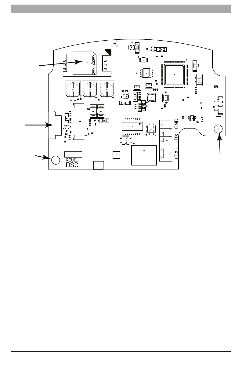
Communicator Configuration with SCW
Mounting
Hole
Mounting
Hole
SIM Card Holder
RJ-45
Connector
(TL2553G(R)-E only)
UA684
Figure 1: Communication Board Connection Points
NOTE: The Alarm Communicator is installed in the SCW prior to shipment by Digital Security Controls (DSC). The Factory
Installation includes insertion of the SIMcard. The SCWshould not be mounted in its final location without performing a
Communicator Test to ensure adequate HSPA/3G coverage for the 3G2055 (R)-E and TL2553G(R)-E Alarm Communicators
Installation Location
The Communicator shall be installed in an indoor location only.
This HSPA/3G/Ethernet Communicator shall be installed by Service Persons only.(Service Person isdefined asa person having appropriate technical training and experience necessary to be aware of hazards to which that person may be exposed in
performing a task and of measures to minimize the risksto that person or other persons). The Communicator shall be installed
and used within an environmentthat provides the pollution degree max 2, over voltages category II, in non-hazardous, indoor
locations only. This manual shall be used with the Installation Manual of the alarm control panel which is connected to the
HSPA/3G/Ethernet Communicator.All instructions specified within the control panel manual must be observed.
All the local rules imposed by local electrical codes shall be observed and respected during installation.
Installing CAT 5 Cable (TL2553G(R)-E only)
A Category5 (CAT 5) ethernet cable must be run from a source with Ethernet/Internet connectivityto the Communicator module, inside the SelfContained WirelessControl Panel cabinet. The Communicator end of the cable must have an RJ-45 plug,
which connects to the Communicator’s RJ-45 jack. All requirementsfor installation of CAT5 ethernet cable must be observed
for correct operation ofthe Communicator,including, butnot limited to,the following:
l Do NOT strip offcable sheathing more than required for proper termination.
l Do NOT kink/knot cable.
l Do NOT crush cable with cable ties.
l Do NOT untwistCAT5 pairsmore than 1.2cm (½”).
l Do NOT splice cable.
l Do NOT bend cable at right angles or make any other sharp bends.
9
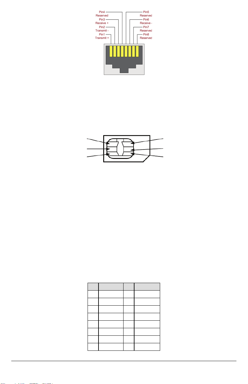
Figure 2: RL-45 Pinout
RJ-45 Connector
SIM Card Pinouts
GND
Vpp
I/O
Vcc
Reset
CLK
NOTE: CAT5 specification requires that any cable bend must have a minimum 5 cm (2 in.) bend radius. Maximum length of
CAT 5 cable is100m (328 ft.).
NOTE: The Ethernet cable shall not be visible when the installation is complete unlessthe install isa surface mountinstallation.
INSERTING/REMOVING THE SIM CARD
Figure 3: SIM Card Pinouts
1. Remove the front cover ofthe SCW Control Panel to accessSIM card holder.
2. Remove power from the SCW and disconnect the backup batteryconnections.
3. On the SIMcard holder push gentlyto slide the cover towards OPEN asindicated bythe arrow on SIM holder. This will
unlatch the SIMcard holder on the side furthest from edge ofthe Communicator.See Figure 1.
4. Lift up the SIMcard holder fromthe side that is nothinged.
NOTE: The SIM card can be damaged by bending or scratching contacts. Use caution when handling the SIMcard.
5. Insert or remove the SIM card, noting the orientation ofthe notches on the SIMcard and the SIMcard holder.
6. When inserting a SIMcard, insert the card in the proper orientation and gentlypush the SIM card holder down and slide
the holder as indicated by the arrow on SIM holder, to LOCK.
7. Apply AC power to panel, and replace the panel cover.
NOTE:Iftwoway audio is enabled you will NOT be able to swap the SIM card with another card.
Communicator Reset
The Communicator can be resetby cycling the power on the SCW.
Establishing a Communication Channel with the SCW Panel.
The Communicator interfaces to the SCW through a keyed 16 pin Ribbon cable. See Table 6 . The keyprevents incorrect connection ofthe ribbon cable connector to the SCW and Communicator. The pinout for the Ribbon cable is provided in the Table
below:
Table 6: Communicator Ribbon cable to SCW
Pin # Signal Pin # Signal
1 PC-LinkTX 2 PC-Link RX
3 GND 4 Vref
5 Vref 6 GND
7 AUD-OUT_N 8 AUD_OUT_P
9 AUD-IN_P 10 AUD-IN_N
11 GND 12 SI
13 GND 14 SO
15 GND 16 Wall Tamper
10

Establishing a communication channel between the Communicator and the SCWis critical to ensuring the desired operation of
the two units. The following steps must be completed during the on-site installation. Program the following to ensure that the
Communicator and the panel will work together as intended.
Initial Programming of Communicator and SCW
1.
Enter [*][8][Installer Code] [Section Number] for panel programming.Record anyvalues that are modified fromtheir
default,in the appropriate Programming Worksheets.
NOTE: When programming Toggle Options, the toggle is ON when the number is displayed and OFF when the number is not
dis played.(e.g.,[1---5---],Toggle Options 1 and 5 are ON,all others are OFF).
2.
Panel Section [167] Cellular/Ethernet InterfaceCommunications ‘Waitfor ACK’: Default value is: 060 seconds.
3. When the communicator isinstalled with the SCW panel, 4 telephone numbers are available to backup one another.
You can set up these 4 telephone numbers to performin one oftwo ways:Backup dialling or Alternate dialling.
a.
Backup dialling: each of the 4 telephone numbers will make 5 dialling attempts in turn, before an FTCtrouble isdisplayed on the keypad.
b.
Alternate dialling: each telephone number makes1 dialling attempt before moving on to the next number,cycling
through each ofthe 4 numbers for a total of 5 timeseach. If all 4 numbers fail the 5 attempts,an FTC trouble is displayed on the keypad.
4.
Panel Sections [301], [302], [303], and[305] can be configured as Primarycommunication paths.
a.
Panel Sections [302], [303], and [305] may also be configured for backup or redundant communications byusing
Panel Section(s) [383] or [351] - [376]. Refer to the SCW panel Installation Manual for more information.
b. If avalid telephone number is programmed, communications will use PublicSwitched Telephone Network (PSTN).
Entering a 4 digit hexadecimal value for a telephone number will change the call routing to the Communicator,as
determined by the number programmed:
DCAAF:Internal (All Receivers).Signals will be routed depending on Section [851] [006] programming.
DCBBF:Ethernet Receiver 1 (Primary).(Notavailable for 3G2055(R)-E).
DCCCF:Ethernet Receiver 2 (Backup). (Notavailable for 3G2055(R)-E).
DCDDF:Cellular Receiver 1 (Primary).
DCEEF:Cellular Receiver 2 (Backup).
NOTE: Add a single ‘F’ asa suffixto the 4 digithex number to populate the unused remainder of the 32 character field.
5.
Panel Section [350]: If anyof the phone numbers have been programmed as DCAA, DCBB, DCCC, DCDD,or DCEE,
panel Section [350]mustbe set to [04]if SIA formator [03] ifContactID (CID) format isused bycontrol panel.
6.
Panel Section [382]: Toggle Option [5], ‘GS/IP Module Enabled’, mustbe set to ON.
7.
Panel Section [401]: Toggle Option [1] must be set to ON in order to performpanel DLS session through Cellular or Ethernet data channel.
8. Panel section [310], account code, auto syncswith the communicator accountcode in section [021]. The panel account
code ([*][8][installer code] [310]), will overwrite the communicator account code section ([*][8][installer code] [850] [021]) if
programmed differently.
NOTE: Keep a record of the SIM card telephone number, it is required by users for SMS Command and Control functions.
(The number can be recorded in the Programming Worksheets Section of this document, under Option [996]). Due to
the nature ofthe SIM card activation processwith Cellular networkcarriers,it can takeup to 24 hours for SIM card activation tobe complete.
SMS Command and Control Functions
SMS Command and Control isavailable on SCW9055/57 panels.Users can send SMS textmessages fromtheir mobile phone
to the GSM phone number assigned to their system. Commandsare only accepted from telephone numbers that have been
programmed in Sections [311]-[318].The system will reject messages sent from telephone numbers that are not on the programmed list.
When the received SMS textmatches a valid Section message, the function is performed on the control panel. Text messages
are not case sensitive and extra spaces are ignored. A User AccessCode maybe required for some SMS messages.
The SMS Message format isin 3 parts: Command, Partition Label (or only the partition number), and Access Code.
Ifan Access Code is included in the message, it issentto the control panel for validation, along with the requested function.
Ifthe panel is configured to require an AccessCode and the code is not sent (or invalid) the panel will fail the function (unsuccessful).
Ifthe panel fails the function, an SMS response message is sent to the user. The SMS response will echo the command sensat,
followed bythe label “unsuccessful”. (e.g., “night arm partition 2 1234 unsuccessful”).
The partition label or partition number may be excluded from the SMS requestin a single partition system (e.g., disarm 9123).
NOTE: The GSM phone number can be viewed in Section [851] [996],and/or [851] [229]or by entering *6, then scrolling down
to “SMS Programming” and scrolling down to “Cellular phone No”.
Label Programming for SMS Message
Programmable Labels can not be modified in Connect24, use DLS IV for label programming only, if labels need to be modified. Before initiating remote programming, record your network’s Public IP Address and port for incoming DLS IV connections.
11

1. Run the DLS IV software on your computer. DLS IV will connectto the unit,using the Public IP address, and make an Ethernet connection. If the Ethernet connection fails, DLS IV will report an error and promptyou to connectusing Cellular.
NOTE: If required, download the DLS IV software from DSC: http://www.dsc.com/index.php?n=library#self.If you select Cellular
connection,DLS will request Connect24 to send an outgoing SMS message to the unit.
2. Connect24 will confirm that the account has DLS service and will provide the Public IP address and portnumber of the
DLS server in an SMS message.
3. SMS message will establish a connection to your computer’sDLS IV software (to change programming labels only).
4. Create an account for the panel/Communicator, select the Communicator type (e.g., SMS - TL2553GR-E) and enter all
relevant information in SMS section.
NOTE: The Cellular telephone number will also be required by the user, to send SMS Command and Control messages to
their system.
5. Program the accountinformation,then click Global Download and choose SMS as the Connection Type. Click OK.
6. The download path configured in Programming Section [005]Toggle Option[4]determines the Cellular or Ethernet path
to be used.
Communicator Placement Test
(3G2055(R)-E /TL2553G(R)-E only)
1. Using the keypad enter the installer mode: [*][8] [installer code] [850].
2. View and record the number ofbars showing on the SCW LCD.
3. Compare with the number ofbars indicated inthe “CSQ Levels” column shown in Table 7 .
4. If 3or more bars are shown, the location is GOOD and no further action is required.
5. If the location is BAD,move the SCWto various suitable locations until 3 or more bars are obtained.
Table 7: Communicator CSQ Levels
Signal Strength CSQ Level SignalLevel (dBm) Installer Action
No Signal 0 -108.8 Checkif Cellular coverage is activein your area.
1 Bar 1 to 4 -108 to -103
2 Bars 5 to 6 -102 to -99
3 Bars 7 to 10 -98 to -90
5 Bars 14 and higher -84 and higher
NOTE: The communicator is capable of indicating signal strength even without an active SIM,but signal indication maytake up
to 1-2 minutes.
Location isBAD. Not suitable for Cellular operation.
Location isGOOD.4 Bars 11 to 13 -90 to -85
Ethernet/Cellular Programming Options
The Programming Sections described in this document can be viewed at the SCW LCD. To start programming enter: [*][8]
[installer code] [851][###],Where ### isthe 3 digit Section number referenced in thissection. The Programming Worksheets at
the end ofthisdocument can be used to record the new values when programming changes have been made from the default
values. Programming Sections are accessed through Connect24. Installers may review/record programming Options at the
panel.
NOTE: Ethernet/Cellular Programming Sections accessed through the panel are for display purposes only. Configuration
changes must be done using Connect24.
System Options
[001] Ethernet IP Address
Default(000.000.000.000)
Enter the IP address of the Communicator. Ensure that the IP addressis unique to your Communicator on the local network.
Formatis 4 fields,each field is a 3 digit decimal number. Valid range: 000-255. If an IP address is programmed in this Section,
the unit will operate with Static IP (DHCP disabled). Sections [002] and [003] must also be programmed when using Static IP
addresses.
NOTE: Default for this Section isDynamic Host Configuration Protocol (DHCP) enabled. When enabled, the DHCP Server will
set values for: IP Address [001], Subnet Mask[002],and Gateway[003].Programming an IP address in this Section will
disable DHCP (StaticIP).
[002] Ethernet IP Subnet Mask
Default(255.255.255.000)
Enter the Ethernet IP SubnetMaskof the Communicator. Format is 4 fields, each field is3 digits. Valid range:000-255.
NOTE: If DHCP is enabled, the DHCP Server will assign the subnet mask for this Section and the programmed value will be
ignored.
12
 Loading...