

Tyco Safety Canada 143G4010 User Manual

3G4010
3G (HSPA) WIRELESS ALARM
COMMUNICATOR
INSTALLATION MANUAL
V4.0
WARNING: This manual contains information on limitations regarding product
use and function and information on the limitations as to liability of the manufacturer. The entire manual should be carefully read.

TABLE OF CONTENTS
Introduction . . . . . . . . . . . . . . . . . . . . . . . . . . . . . . . . . . . . . . . . . . . . .1
Features . . . . . . . . . . . . . . . . . . . . . . . . . . . . . . . . . . . . . . . . . . . . . . . .1
Technical Specifications . . . . . . . . . . . . . . . . . . . . . . . . . . . . . . . . . . .1
Ratings . . . . . . . . . . . . . . . . . . . . . . . . . . . . . . . . . . . . . . . . . . . . . . . . .1
Identification of Parts . . . . . . . . . . . . . . . . . . . . . . . . . . . . . . . . . . . . . .2
Description . . . . . . . . . . . . . . . . . . . . . . . . . . . . . . . . . . . . . . . . . . . . . .3
Installing the 3G4010 . . . . . . . . . . . . . . . . . . . . . . . . . . . . . . . . . . . . . .4
Connecting the 3G4010 . . . . . . . . . . . . . . . . . . . . . . . . . . . . . . . . . . . .4
Status LEDS . . . . . . . . . . . . . . . . . . . . . . . . . . . . . . . . . . . . . . . . . . . . .5
Operating Principles . . . . . . . . . . . . . . . . . . . . . . . . . . . . . . . . . . . . . .6
Simulated Landline Mode . . . . . . . . . . . . . . . . . . . . . . . . . . . . . . . . . .6
Panel Transmission Monitoring (PTM) . . . . . . . . . . . . . . . . . . . . . . . . .6
Wireless Communications Sequence . . . . . . . . . . . . . . . . . . . . . . . . .6
Inputs . . . . . . . . . . . . . . . . . . . . . . . . . . . . . . . . . . . . . . . . . . . . . . . . . .6
Outputs . . . . . . . . . . . . . . . . . . . . . . . . . . . . . . . . . . . . . . . . . . . . . . . .7
Activating the Outputs . . . . . . . . . . . . . . . . . . . . . . . . . . . . . . . . . . . . .7
Swinger Shutdown . . . . . . . . . . . . . . . . . . . . . . . . . . . . . . . . . . . . . . . .7
Hardware Default . . . . . . . . . . . . . . . . . . . . . . . . . . . . . . . . . . . . . . . . .7
Low Power Radio Shutdown . . . . . . . . . . . . . . . . . . . . . . . . . . . . . . . .8
CONNECT 24 Remote Programming . . . . . . . . . . . . . . . . . . . . . . . . .8
Troubleshooting Guide . . . . . . . . . . . . . . . . . . . . . . . . . . . . . . . . . . . .8
3G4010 Wiring Diagrams . . . . . . . . . . . . . . . . . . . . . . . . . . . . . . . . . .12
i

IMPORTANT
The equipment is fixed, wall-mounted and shall be installed in the position specified in
these instructions. The equipment enclosure must be fully assembled and closed, with
all the necessary screws/tabs and secured to a wall before operation. Internal wiring
must be routed in a manner that prevents:
- Excessive strain on wire and on terminal connections
- Loosening of terminal; connections
- Damage of conductor insulation
WARNING: Never install this equipment during a lightning storm!
Instruct the end-user to:
- Not attempt to service this product. Opening or removing covers may expose the user
to dangerous voltages or other risks. Any servicing shall be referred to trained service
persons only.
- Use authorized accessories only with this equipment.
Do not dispose of the battery in fire or water. Disposing of the battery in a fire will cause
rupture and explosion.
Do not dispose of the waste battery as unsorted municipal waste. Consult your local
regulations and /or laws regarding recycling with regard to this lithium battery pack. Doing
so will help protect the environment. Some of the materials that are found within the bat-
tery could become toxic if not disposed of properly and may affect the environment
.
ii

Introduction
The 3G4010 is a wireless communicator that sends alarm system information to an Sur-Gard System I, II,
III or IV receiver through a 3G (HSPA) or 2G (GPRS) wireless network. This wireless communicator can be
used with UL/ULC Listed compatible control units, as indicated in the manufacturer's installation instructions.
NOTE: The 3G4010 is designed to work with SIA and the Contact ID communication format as described
in SIA DC-05 Standard. Before completing the field installation of the alarm monitoring system please
ensure communication with the supervising central station is successful by sending several events and
getting confirmation that they have been received.
Features
• Compatible with 4-digit or 10-digit Contact ID communication format as described in SIA DC-05
Standard. Example of suitable compatible alarm panels: DSC Models PC1864, PC1832, PC1616,
PC4020.
• Simulates landline
• Switches automatically to the 3G
(e.g., line down)
• Wireless Signal Indicator
• Four programmable outputs
• Contains one 12V - 1.2 Ah battery
• Case Tamper Output
• Landline overvoltage protection
• Tri-band UMTS/HSPA; Quad-Band GSM/EDGE Radio
• Four programmable inputs
• 3G (HSPA)/2G (GPRS) / Internet communication with Sur-
• Panel transmission monitoring for up to
Technical Specifications
The input voltage to the 3G4010 can be drawn from the UL/ULC Listed control panel or provided by an
external UL/ULC Listed power supply rated for the application (external power-limited source).
NOTE: The power supply must be Class 2, Power Limited. For residential applications a suitable power adap-
tor is model DSC ADP1310-NAU (for USA) a
Ratings
Power Supply Ratings - Input Voltage (for long-term operation)
CON5-OFF with internal battery: . . . . . . . . . . . . . . . . . . . . . . . . . . 13.8V
CON5-ON without internal battery: . . . . . . . . . . . . . . . . . . . . . 13.8V
NOTE: When the input voltage drops below 13.5VDC, the internal battery supplied with the 3G4010
will not be charged. In order to maintain a charged level for the internal battery, the power supply
must have a minimum voltage of 13.5V
Current Consumption
CON5-OFF with internal battery: . . . . . . . . . . . . . . . . . . . . . . . . . . . . . . . 120mA*
CON5-ON without internal battery: . . . . . . . . . . . .
* Plus any current drawn from the 3G4010 AUX+ terminal
Working Voltage Range . . . . . . . . . . . . . . . . . . . . . . . . . . . . . . . . . . 9-14VDC
Battery: . . . . . . . . . . . . . sealed, rechargeable type, rated 12V
Battery charging voltage: . . . . . . . . . . . . . . . . . . . . . . . . . . . . . . . . . . .
Battery charging current: . . . . . . . . . . . . . . . . . . . . . . . . . . . . . . . . . . . . 50mA
NOTE: Battery must be replaced every 3-5 years.
Operating frequency: . . . . . . . . . . . . . . . . . . . . . . . . . . . . . . . . . 850/1900MHz
Antenna gain: . . . . . . . . . . . . . . . . . . . . . . . . . . . . . . . . . . . . . . . . .
Environmental Specifications
Operating temperature:
Humidity: . . . . . . . . . . . . . . . . . .
Mechanical Specifications
Dimensions (metal enclosure, painted):
Weight (without battery): . . . . . . . . . . . . . . . . . . . . . . . . . . . . . . . . 900g / 3.2oz
Internal Event Buffer (communications): . . . . . . . . . .
Simulated Telco Loop specifications (TIP/RING)
On-Hook Voltage: . . . . . . . . . . . . . . . . . . . . . . . . . . . . . . . . . . . . . . .
Loop Current . . . . . . . . . . . . . . . . . . . . . . . . . . . . . . . . . . . . . . . . . .
Loop Resistance . . . . . . . . . . . . . . . . . . . . . . . . . . . . . . . . . . . . . .
Alternate construction
Dimensions (enclosure for 3G4010CF): . . . . . . . . 165mm x 257mm x 76mm / 6.3” x 10.1” x 3”
Weight (alternate constru
. . . . . . . . . . . . . . . . . . . . . . . . . . . . 0°C-49°C (32°F-120°F)
ction enclosure without battery): . . . . . . . . . . . . . . 1300g / 2.8lbs
(HSPA) or 2G (GPRS) network in the event of landline trouble
Gard System I / II / III / IV
four phone numbers
nd model DSC ADP1310-NA (for Canada).
DC required
DC recommended
DC
to ensure a sufficient battery charge in all conditions of use.
. . . . . . . . . . . . . . . . . 500mA*
/1.2Ah (for 24hr standby time)
13.5VDC
2.0dBi
. . . . . . . . . .93%RH Maximum (non-condensing)
. . . . . . . . 138mm x 224mm x 55mm / 5.4” x 8.8” x 2.2”
. . . . . . . . 256 Events (not viewable)
35VDC
25mA
600 Ohms
1
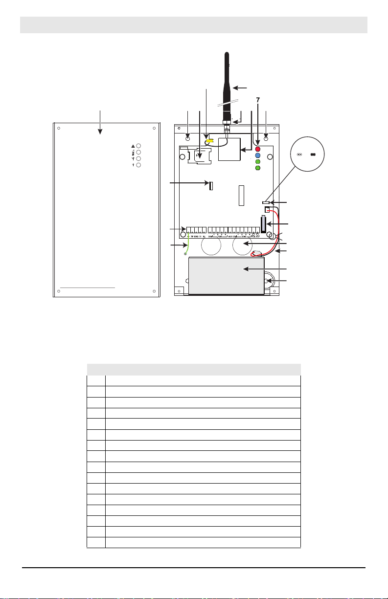
Identification of Parts
CON3
LED2
BAT+
NO
OPEN
+
LED1
BAT-
-
LED4
LED3
BAT
BAT
UA673
SERIAL N UMBE R
1
44
5
3
2
16
6
9
10
8
11
13
12
15
14
4
CON5
tie wrap
BAT NO BAT
All circuits are classified for UL installations as Power Limited/Class II Power Limited except for the battery leads which are not power limited. Do not route any wiring over circuit boards. Maintain at least 1”
(25.4mm) separation. A minimum 1/4” (6.4mm) of separation must be maintained at all points between
Power Limited wiring and all other non-Power Limited wiring. Route wires as indicated above.
3G4010
Figure 1 - Parts
Table 1: Parts
1 Metal Casing
Parts
2 3G Antenna 3 Antenna Mounting Hardware 4 Anchor Screw Holes (3mm) 5 Antenna Connector 6 SIM Card Holder 7 Status LEDs (see page 5) 8 CON5 Battery Setting Jumper
9 PC-Link Connector 10 Tamper Switch 11 Terminal Blocks 12 Battery Leads 13 Cable Entry 14 Earth Ground Wire 15 12V/1.2Ah Battery 16 3G (HSPA) Radio Module
2

This equipment 3G4010 is fixed and shall be installed by Service Persons only (Service Person is
defined as a person having the appropriate technical training and experience necessary to be
aware of hazards to which that person may be exposed in performing a task, and of measures
available to minimize the risks to that person or other persons). It shall be installed and used
within an environment that provides the pollution degree max 2, over voltages category II, in
non-hazardous, indoor locations only. This manual shall be used with the Installation Manual of
the relevant alarm control panel. All instructions specified within that manual must be observed.
Description
This 3G4010 manages transmissions to a central station and can simulate the landline in the event of
trouble (e.g., landline down) or even substitute the landline completely in areas where the 3G or 2G
wireless service is provided and a landline is not available.
The 3G4010 has the capability of communicating alarm signals via the 3G or 2G data network. This
capability ensures a fast, reliable path to central stations equipped with a Sur-Gard System I / II / III / IV
receiver. By connecting a 3G4010 to a control panel's standard PSTN interface, telephone-based
Contact ID signals are decoded and seamlessly routed through the 3G or 2G network to any of the
compatible receiver options.
The performance of the 3G4010 depends greatly on wireless network coverage. Therefore, it should not
be mounted without first performing placement tests to determine the best location for reception
(minimum of one green LED ON). Optional antenna kits – GS15/25/50-ANT (15ft/4.6m, 25ft/7.6m or
50ft/15.2m) – are available.
The 3G4010 requires enrollment with CONNECT 24 to operate. Dealer application forms and
additional information on the CONNECT 24 Voice Response Unit (VRU) and web user interface can
be found at www.connect24.com, or at the following telephone numbers:
USA 1-888-251-7458 CANADA 1-888-955-5583
For UL Residential Fire and Burglary installations, the 3G4010 is listed as a sole means of communication
or as a back up when used in conjunction with a POTS line (dialer). For UL Residential Fire installations,
when installed in the alternate enclosure for 3G4010CF, the 3G4010 has provisions for 24-hour standby
power.
For UL Commercial Burglary installations, the 3G4010 is listed as a sole means of communication
(supervision window of 200s required at monitoring station) or as a back-up when used in conjunction
with a POTS line (dialer).
The 3G4010 shall be powered from any compatible listed control unit or compatible listed power supply that
complies with the ratings specified on page 1. The power supply shall be listed for burglary applications and
provide a minimum of 4 hours standby power capabilities. An example of a suitable listed compatible control
unit is the DSC Model PC1864 with an AUX output rated 11.1 - 12.6VDC. An example of a suitable Listed
power supply is DSC Model PC5204 with an AUX output rated 11.6 - 12.6VDC.
For ULC Commercial Fire Monitoring installations the 3G4010 is listed as a passive communication
system when used in conjunction with a POTS line (dialer). Fire alarms shall be sent simultaneously over
both communication methods (wireless network and PSTN).
For ULC Commercial Burglary installations the 3G4010 is listed as a passive communication system with
communication line security level P2 when used as a back up in conjunction with a POTS line (dialer).
For ULC Residential Fire and Burglary installations the 3G4010 is listed as a sole means communication
or as a back up when used in conjunction with a POTS line (dialer).
ATTENTION: The 3G4010 is equipped with a current limiter that limits current demand on the
12V
DC power input to 120mA. The current limiter is enabled by default (see Part #8 in 'Identifica-
tion of Parts’ on page 3) with CON5 in the OFF position. The current limiter can be disabled
(bypassed) with CON5 in the ON position. When the 3G4010 12V
Alarm Panel Aux+ output, DSC recommends that the current limiter be active to limit the demand
from the panel. If the alarm panel is intended to supply all of the current demand, you must
ensure that the panel can supply 500mA and that the current limiter is disabled. When the 3G4010
is transmitting, the current demand exceeds 120mA (500mA). With the current limiter in place,
the additional current demand is supplied by the 3G4010 battery.
NOTE: With the current limiter active, there is a risk of discharging the 3G4010 battery when
transmission frequency is high. The back up battery must always be connected to the device when
the current limiter is enabled.
If power to the 3G4010 is supplied by an external power supply (recommended 13.8 VDC, 0.7A), the
current limiter must be disabled to allow the full current demand to be supplied. In this configuration
the 3G4010 battery is not required.
DC power input is supplied by the
3

Installing the 3G4010
CONNECT 24 Enrolment Information
Only authorized dealers can enrol a 3G4010 with CONNECT 24. Dealer app
information on the CONNECT 24 Voice Response Unit (VRU) can be found at the CONNECT 24 website
www.connect24.com. Please contact CONNECT 24 at the number below for assistance:
USA 1-888-251-7458 CANADA 1-888-955-5583
NOTE: Step 1 should be performed before turning on the 3G4010 unit.
NOTE: Before inserting or removing the SIM card, please ensure the unit is turned off.
STEP 1 - Initialize the 3G4010 with Connect 24
VRU Enrolment
Call the VRU at the toll-free number: 1-866-910-3865. Follow the voic
number, installer ID number, installer PIN number and SIM number. Ensure that all information is
available and at hand before calling the VRU. It is recommended that the radio initialization be
performed at least 24 hours in advance of installation to ensure SIM activation will be complete.
WEB Enrolment
If you have credentials for www.connect24.com, you may
check with your Connect 24 Master Reseller or Connect 24 Customer Service for more details.
STEP 2 - Determine the Best Signal Location
1. Unscrew the four screws securing the front panel to the cabinet.
2. Fit the 3G antenna [2]. Ensure the 3G antenna mo
3. Attach the 3G radio module with the 3G antenna co
4. Turn on the 3G4010 and check the signal strength.
4.1 Connect the battery to the RED
4.2 Connect the DC power source to +/- 12V terminals.
5. Allow the unit to power up.
NOTE: The green LEDs will indicate the signal strength. The bottom green LED must be ON for
the location to be acceptable. Please refer to the ‘Status LEDs’ section for more information.
6. Power down the 3G4010 by removing the DC power source and battery leads.
STEP 3 - Connect the 3G4010
1. Using the cabinet, mark the four screw locat
NOTE: Check for cable conduits and water pipes before drilling.
2. Using anchor screws (not provided), mount the cabinet to the wall.
3. Run the cables through the cable entry [13] or through the cabinet kno
4. Complete the connections on th
NOTE: Ensure that power and Telco circuit connections are made only after the cabinet has been
secured to the building or structure, and has been connected to the protective earth ground.
Descriptions of the terminals can be found in the ‘Connecting the 3G4010’ section.
5. Reattach the front cover [1] securely to the cabinet.
NOTE: Please refer to Figure 2 at the end of this manual for wiring diagram.
and BLK battery leads.
ions. Drill the anchor screw holes.
e terminal blocks [11].
also initialize the 3G4010 via the web. Please
unting hardware is fastened securely [3].
nnector. Ensure that the connector is secure.
lication forms and additional
e prompts and enter your profile
Remove the front panel.
ckouts.
Connecting the 3G4010
(1) Earth Ground - This terminal must be connected to the Mains Earth, in order to comply with the
Telecommunications Network Safety Standards
TIP (2) / RNG (3) External Telephone Line - These terminals must be conn
incoming telephone line.
T1 (4) / R1 (5) Internal Telephone Line - These terminals must be connected to the
the control panel.
COM (6,14) Common - Th
PGM1 (7), PGM2 (8), PGM3 (9), PGM4 (10) Programmable Open-collector Outputs - Thes
outputs can be activated by programmed events. Refer to ‘Activating the Outputs’ for details. The
maximum current sink of each output must not exceed 50mA.
AUX+ (11) Auxiliary 12V Output - +12V
NOTE: Electrical current drawn from this terminal is drawn directly from the power supply. This
is terminal is connected internally to Power Ground.
(Overvoltage Protection Requirements).
ected directly to the
TIP and RING of
e
Output, 200mA PTC Protected.
4

must be added to the 3G4010 current when determining the total draw on the host panel or
power supply. Jumper CON5 does not limit the electrical current available on this output.
Tamper (12-13) - These terminals are connected in series to the Tamper switch [10]. They will close
when the cabinet is properly closed, and will open when the front cover is removed.
Z1-Z4 (15-16-17-18) Programmable Inputs - T
to ‘Inputs’ for details.
12V (19), COM (20) Device Power Supply
supply. Once the connections are completed, connect the battery leads (Red and Black wires, [12] in
Figure 1) to a 12V, 7Ah battery.
Jumper CON5
CON5 ON
supply. Supply must be capable of up to 700mA. The 3G4010 battery must not be connected.
CON5 OFF - Curr
Supply must be capable of 120mA plus any current drawn from AUX+ terminal. 3G4010 battery
must be installed for proper operation.
NOTE: The power supply must have a minimum voltage of 13.5V to ensure a sufficient battery
charge. An example of a suitable power supply is the DSC Model ADP1310-NA with DC output
rated 13.8 VDC, 1Amp. This is to be used in conjunction with a 12V/7Ah rated battery for UL/ULC
listed residential installations.
NOTE: This mode of operation must not be used fo
NOTE: When disposing of batteries, follow the instructions and precautions printed on the batteries, and contact your municipal offices for information on the disposal of used batteries.
- Full power, including standby capacity, comes from the host panel or external power
ent limiting mode, the host panel or external supply provides standby current.
hese terminals can be set up to trigger events. Refer
- These terminals must be connected to a rated power
r ULC Listed Fire Monitoring installations.
Status LEDs
The 3G4010 interface has four status LEDs. The following describes the control panel status LEDs.
NOTE: The top two LEDs blink during the Initializing and Programming phases.
RED - This LED is normally Off; but, it will flash in the event of a trouble. This LED will switch on
within three minutes in the event of wireless Module [16] trouble, or when the wireless Network is
unavailable, ‘No Ser
the number of flashes, by priority. When turned on, the 3G4010 checks for the trouble conditions to
be restored in the order listed below. The 3G4010 indicates the status of the highest priority,
unrestored trouble condition with the corresponding number of flashes of the red LED. Once the
highest priority trouble condition has been cleared, the next highest priority trouble condition is
displayed (if applicable).
1 flash - Battery Trouble (Battery with low voltage
2 flashes - Radio/SIM
3 flashes - Wireless Netwo
4 flashes
5 flashes
ration is ready, turn off power for
6 flashes - Receiver not
7 flashes - Power Supply Trouble (DC power supply absent)
Off
- Insufficient Signal Strength (poor location)
- Connect 24 Configuration SMS Trouble (Improper VRU programming. Once the configu-
- No Troubles
YELLOW - When this LED is On (solid), a Phone Line Trouble condition exists. This LED switches
on when the interface switches to the Wireless Network (due to
This LED flashes slowly in the event of an incoming or outgoing voice call (regardless of the
operating status of the landline). This LED can also flash quickly once (Wireless TX) or twice
(Wireless RX).
GREEN (Top) - When this LED is On, the reception is optimal. This LED switches On only when
the other Green LED is on.
GREEN (Bottom) - If this LED is Off and the Red LED is On, the Wireless Network service is
unavailable (NO SERVICE). This LED flashes when the Wireles
LED is on, the 3G4010 is able to communicate with the 3G (HSPA) or 2G (GPRS) network.
vice’. If this LED flashes, the following list indicates the specific trouble based on
output)
Trouble (Battery absent or SIM Card disconnected)
rk Problem (SIM not active, poor signal strength, antenna not connected)
2-3 seconds to allow the unit to restart and request again)
available (Improper VRU programming, receiver absent)
a Landline trouble condition).
s Network reception is poor. If this
5
 Loading...