

Tyco Safety Canada 13HS2KRFP9 Users manual
HS2016/2032/2064/2128 Alarm Panel
DRAFT 3
V1.0 User Manual
WARNING: This manual contains information on limitations regarding
product use and function and information on the limitations as to liability
of the manufacturer. The entire manual should be carefully read.

Table of Contents
DRAFT 3
1 Quick Reference 5
2 About your Security System 6
2.1 The HS Series Security System ............................... .................................6
2.1.1 Carbon Monoxide Detection (must be enabled by your Installer)..............6
2.1.2 Fire Detection (must be enabled by your Installer) ....................................6
2.1.3 Testing.......................................................................................................6
2.1.4 Monitoring ..................................................................................................6
2.1.5 Maintenance ..............................................................................................6
2.1.6 General System Operati o n .......................................... ... .. ... .. ....................7
3 System Types 8
3.1 System Models ..........................................................................................8
3.2 Keypads.....................................................................................................8
3.2.1 LCD Icon and LED Keypad Symbols.........................................................8
4 Securing the Premises 9
4.1 Arming the System with the Keypad..........................................................9
4.1.1 Away Arming the System with the Keypad ............. .. ... ... .. .........................9
4.1.2 Stay Arming the System with the Keypad..................................................10
4.1.2.1 Silent Exit Delay.........................................................................................10
4.1.3 Night Arming the System with the Keypad.................................................10
4.1.4 No-Entry Arming ... .. ... ... .................................. .................................. .........11
4.2 Leaving when the System is Already Armed - Quick Exit..........................12
4.3 Arming Errors and Exit Faults............................................................ ........12
4.3.1 Arming Errors.............................................................................................12
4.3.2 Audible Exit Faults.....................................................................................12
4.4 Disarming the system ................................................................................13
4.4.1 Disarming Error..........................................................................................13
4.5 Bypassing Zones .......................................................................................13
4.5.1 Bypass Groups ..........................................................................................15
5 Emergency Keys and Alarms 17
5.1 Emergency Keys........................................................................................17
5.2 Alarms........................................................................................................17
5.2.1 Intrusion (Burglary) Alarm - Continuous Siren...........................................17
5.2.2 Fire Alarm - Pulsed Siren................ ... .. .................................. ....................17
5.3 Carbon Monoxide Alarm - 4 beeps, long pause , 4 beeps..........................18
5.4 Resetting Sensors .....................................................................................18
5.5 Viewing Alarms in memory ... .. ... .. ... ... .................................. ......................18
5.5.1 Alarm Messages .......................................................... ..............................18
6 Wireless Keys and other Devices 19
6.1 Using the 2-way Wireless Key ...................................................................19
6.2 Using Proximity Tags......... ... .. ... .................................. ..............................19
6.3 SMS Command and Control......................................................................19
2

Table of Contents
DRAFT 3
6.3.1 Using the Keypad to Lookup the Number to Call for SMS Commands.....20
6.3.2 Sending SMS Commands to your System ................................................20
6.3.3 SMS Responses from you r Sy st e m....................................... ... ... .. ... .........21
7 Managing Users 22
7.1 User Codes.................................................. .................................. ............22
7.1.1 Access Codes............................................................................................23
7.1.2 Enrolling and Deleti ng Pro x im i ty Tags...................................... ... .. ............23
7.1.3 Enrolling Wireless Keys ..................... .................................. ......................24
7.1.4 Naming a User. .. ... .. ... .................................. .................................. ............24
7.1.5 Assigning a Partition to a User code..........................................................25
7.2 Configuring additional User Options..........................................................25
7.3 Maintenance Code............................................................ .........................26
8 Configuring User Functions 27
8.1 Selecting your language.................................................................. ..........27
8.2 Turning the Chime ON/OFF.......................................................................27
8.3 User Functions . .................................. .................................. ......................27
8.3.1 Event Buffer ...............................................................................................28
8.3.2 Setting the Time and Date .........................................................................28
8.3.3 Enabling/Disabling the Auto Arm/Disarm Feature.....................................28
8.3.4 Setting the Auto Arm Time.............. ... .. ... ... .. .................................. ............28
8.3.5 Allowing the installer to service your system remotely - DLS....................29
8.3.6 User Callup............................. ... .. ... .................................. .........................29
8.3.7 Late to Open ..............................................................................................29
8.3.8 Changing the Brightness of the LCD keypad.............................................30
8.3.9 Changing the Contrast of the LCD keypad ...............................................30
8.3.10 Setting the Buzzer volume.........................................................................30
9 Managing Troubles 31
9.1 Trouble Conditions................................. ....................................................31
10 Managing Partitions 33
10.1 Partition vs. Global Keypad .......................................................................33
10.1.1 Single Partition Operation..........................................................................33
10.2 Global/Multiple Parti ti on Op eration. ... .. ... .................................. .................33
10.2.1 Loaning a Keypad to Another Partition......................................................34
10.3 Global Zones .............................................................................................34
10.3.1 Fire and CO Zone Types ...........................................................................34
11 Testing your System 36
11.1 System Test...............................................................................................36
12 Additional Features 37
12.1 Audio Verification.......................................................................................37
12.2 Video Verification................................................................ .......................37
3

Table of Contents
DRAFT 3
12.2.1 System Lockout due to Invalid Attempts................... ... ... .. ... ......................37
12.3 Command Outputs............................................. ........................................37
13 Regulatory Agency Statements 38
14 Installer Warning 40
15 Safety Instructions 41
15.1 Regular Maintenanc e an d Tr ou b les h oo ti n g......................................... .. ... .41
15.1.1 Cleaning.....................................................................................................41
15.1.2 Troubleshooting.........................................................................................41
16 EULA 42
17 Locating Smoke and CO Detectors 43
17.1 Smoke Detectors .... ... ... .. ... ... .................................. .................................. .43
17.2 Fire Escape Planning.................................................................................44
17.3 Carbon Monoxide Detectors....................................................... ...............44
18 Reference 45
18.1 System Information....................................................................................45
18.2 Service Contact Information ......................................................................45
18.3 Access Code and Sensor / Zone information.................... ........................46
4
1 Quick Reference
*
*
*
*
***
***
*
***
*
***
*
*
6
0
1
*
4
*
612
*
6
1
3
*5*
*
2
*
3
*
6
0
4
*
615
DRAFT 3
The HS Series Alarm System uses a menu based navigation system. The scroll keys are used to
cycle through the list of actions contained within the current menu. However, many actions can also be
accessed using a shortcut key. If an action can be accessed using a shortcut key, the key will be listed in the
instructions below. If you see [Scroll] use the keys to cycle to the listed menu item. Lookup
detailed information on any of the listed actions using the accompanying Section number.
NOTE: Some features must be enabled by installer.
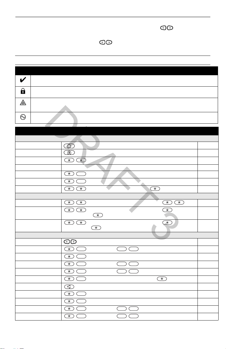
Status Lights
Ready - Indicates system normal. Must be on to arm system. All zones must be secured or bypassed and the system
disarmed for this light to activate.
Armed- Indicates system is armed. If the Ready light and the Armed light are both on it indicates an Exit Delay is in
progress.
Trouble - On indicates a system malfunction or tamper. Flashing indicates that the keypad has a low battery
condition. Follow the instructions displayed or enter [*][2] to view trouble. Correcting the trouble turns of the
indicator.
AC Power - Indicates AC Power is present. The AC Power light will turn off when AC is absent.
Action Press Section
Arming and Disarming
Awa y Arm
Stay Arm
Night Arm
Disarm [Access Code] 4.4
No-Entry Arming
Quick Arm/Quick Exit 4.1.1
Bypass Zone
Bypassing
Recall Last Bypass
Clear Bypass
Load Bypass Group
Common Functions
Select Language
Set Time and Date
Turn Chime ON/OFF 8.2
Change Brightness
Change Contrast
Add/delete user
Reset Sensors 5.4
View Troubles 9.1
View Alarms 5.5
Perform System Test
Buzzer Volume
for 2 seconds
for 2 seconds
+ [Access Code]
9
+ [Access Code]
0
+ [Access Code] + [3 Digit Zone #] +
+ [Access Code] + [Scroll] Bypass Options +
Clear Bypasses +
Bypass Group +
+ [Access Code] + [Scroll] Bypass Options + + [Scroll]
+ [Access Code] + [Scroll] Bypass Options + + [Scroll]
for 2 seconds
[Master Code] +
[Master Code] +
[Master Code] +
+ [Access Code] + [Scroll] Access Code +
[Master Code] +
[Master Code] +
4.1.1
4.1.2
4.1.3
4.1.4
4.5
4.5
4.5
4.5.1
8.1
8.3.2
8.3.8
8.3.9
7.1.1
11.1
8.3.10
5

2 About your Security System
DRAFT 3
2.1 The HS Series Security System
Your DSC Security System has been designed to provide you with the greatest possible flexibility and
convenience. Read this manual carefully and have your installer instruct you on your system's operation
and on which features have been implemented in your system. All users of this system should be equally
instructed in its use. Fill out 18.1 “System Information” page with all of your zone information and access
codes and store this manual in a safe place for future reference.
NOTE: The HS Series security system includes specific false alarm reduction features and is classified
in accordance with ANSI/ SIA CP-01-2000 Control Panel Standard - Features for False Alarm
Reduction. Please consult your installer for further information regarding the false alarm
reduction features built into your system as all are not covered in this manual.
2.1.1 Carbon Monoxide Detection (must be enabled by your Installer)
This equipment is capable of monitoring carbon monoxide detectors and providing a warning if carbon
monoxide is detected. Please read the Family Escape Planning guidelines in this manual and instructions
that are available with the carbon monoxide detector.
2.1.2 Fire Detection (must be enabled by your Installer)
This equipment is capable of monitoring fire detection devices such as smoke detectors and providing a
warning if a fire condition is detected. Good fire detection depends on having adequate number of detectors
placed in appropriate locations. This equipment should be installed in accordance with NFPA 72 (N.F.P.A.,
Batterymarch Park, Quincey MA 02269). Carefully review the Family Escape Planning guidelines in this
manual.
2.1.3 Testing
To insure that your system continues to function as intended, you must test your system weekly. Please
refer to section 11 "Testing your System" in this manual. If your system does not function properly, call
your installer for service.
2.1.4 Monitoring
This system is capable of transmitting alarms, troubles & emergency information to a central station. If you
initiate an alarm by mistake, immediately call the central station to prevent an unnecessary response.
NOTES: The monitoring function must be enabled by the installer before it becomes functional.
There is a communicator delay of 30 seconds in this control panel. It can be removed, or it can
be increased up to 45 seconds, at the option of the end-user by consulting with the installer.
2.1.5 Maintenance
With normal use, the system requires minimum maintenance. Note the following points:
• Do not wash the security equipment with a wet cloth. Light dusting with a slightly moistened cloth
should remove normal accumulations of dust.
• Use the system test described in “Testing Your System” to check the battery condition. We recommend, however, that the standby batteries be replaced every 3-5 years.
• For other system devices such as smoke detectors, passive infrared, ultrasonic or microwave motion
detectors or glassbreak detectors, consult the manufacturer’s literature for testing and maintenance
instructions.
6

2 About your Security System
DRAFT 3
2.1.6 General System Operation
Your security system is made up of a DSC control panel, one or more keypads and various sensors and
detectors. The control panel will be mounted out of the way in a utility closet or in a basement. The metal
cabinet contains the system electronics, fuses and standby battery.
All the keypads have an audible indicator and command entry keys. LED keypads have a group of zone and
system status lights. The LCD keypad has an alphanumeric liquid crystal display (LCD). The keypad is
used to send commands to the system and to display the current system status. The keypad(s) will be
mounted in a convenient location inside the protected premises close to the entry/exit door(s).
The security system has several zones of area protection and each of these zones will be connected to one
or more sensors (motion detectors, glassbreak detectors, door contacts, etc.). A sensor in alarm will be
indicated by the corresponding zone lights flashing on an LED keypad or by messages on the LCD keypad.
NOTE: Only the installer or service professional shall have access to the control panel.
7
3 System Types
5
9
6
12 7
10
11
1
8
15
2
3
4
17
16
14
13
5
9
7
6
HS2ICN Series HS2LED Series
DRAFT 3
3.1 System Models
HS2016 16 Zone Alarm System
HS2016-4 16 Zone Alarm System
HS2032 32 Zone Alarm System
HS2064 64 Zone Alarm System
HS2128 128 Zone Alarm System
3.2 Keypads
The HS Series Alarm System supports a variety wireless, hardwired and proximity sensor LCD, LED and
Icon keypads.
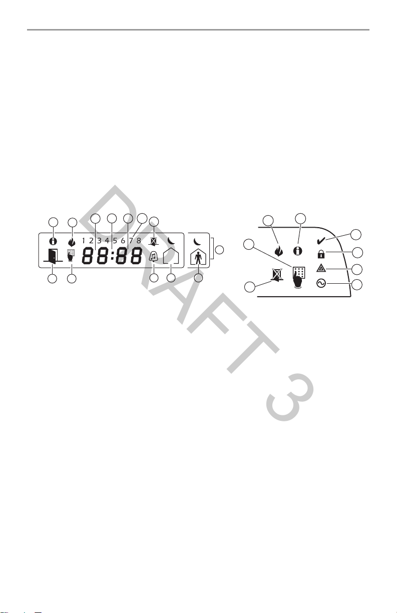
3.2.1 LCD Icon and LED Keypad Symbols
1 Clock Digits 1, 2
2 : (Colon)
3 Clock Digits 3, 4
41 to 8
5Memory
6 Bypass
7 Program
8Away
9Fire
10 Stay
11 Chime
12 OPEN
13 AC
14 System Trouble
15 Night
16 Ready Light (green)
17 Armed Light (red)
These two 7 segment clock digits indicate the hour d igits when the local clock is
active, and identify the zone when the OPEN or ALARM icons are active. These two
digits scroll one zone per second from the lowest zone number to the highest when
scrolling through zones.
This icon is the hours/minutes divider and will flash once a second when the local
clock is active.
These two 7 segment displays are the minute digits when the local clock is active.
These numbers identify troubles when [Q][2] is pressed.
Indicates that there are alarms in memory.
Indicates that there are zones automatically or manually bypassed .
Indicates that the system is in Installer’s Programming, or the keypad is busy.
Indicates that the panel is armed in the Away Mo de.
Indicates that there are fire alarms in memory.
Indicates that the panel is armed in the Stay Mode.
This icon turns on when the Chime function key is pressed to enable Door Chime on
the system. It will turn off when the chime function key is pressed again to disable
Door Chime.
This icon is used with clock digits 1 and 2 to indicate violated zones (not alarm) on
the system. When zones are opened, the OPEN icon will turn on, and 7 segment displays 1 and 2 will scroll through the violated zones.
Indicates that AC is present at the main panel.
Indicates that a system trouble is active.
Indicates that the panel is armed in the Night Mode.
If the Ready light is on, the system is ready for arming.
If the Armed light is on, the system has been armed successfully.
8
 Loading...