

Tyco Safety Canada 119057G, 119057 User Manual
Self Contained Wireless Alarm System
DRAFT
SCW9055/SCW9057 v1.0 User Manual
WARNING: This manual contains information on limitations regarding product use and
function and information on the limitations as to liability of the manufacturer.
The entire manual should be carefully read.
FCC COMPLIANCE STATEMENT
Telephone
Computer
Telephone
Telephone
Fax Machine
Alarm Dialing
Equipment
RJ-31X
Jack
Unused
RJ-11 Jack
Telephone
Line
Network
Service
Provider's
Facilities
Customer Premises Equipment and Wiring
Unused
RJ-11 Jack
Network
Demarcation
Point
Answering
System
DRAFT
This device complies with Industry Canada licence-exempt RSS standard(s). Operation is subject to the following two
conditions: (1) this device may not cause interference, and (2) this device must accept any interference, including interference
that may cause undesired operation of the device.
Cet appareil est conforme avec Industrie Canada exempts de licence standard RSS (s). Le fonctionnement est soumis aux deux
conditions suivantes: (1) cet appareil ne peut pas provoquer d'interférences et (2) cet appareil doit accepter toute interférence,
y compris les interférences qui peuvent causer un mauvais fonctionnement de l' appareil.
CAUTION: Changes or modifications not expressly approved by Digital Security Controls could void your authority to use this equipment.
This equipment has been tested and found to comply with the limits for a Class
B digital device, pursuant to Part 15 of the FCC Rul es. These limits are desig ned
to provide reasonable protection against harmfu l inter ferenc e in a res iden tial i nstallation. This equipment generates, uses and can radi ate radio frequency energy and, if not installed and used in accordance with the instructions, may cause
harmful interference to radio communications. However, there is no guarantee
that interference will not occur in a particular installatio n. If this equipment do es
cause harmful interference to radio or television reception, which can be determined by turning the equipment off and on, the user is encouraged to try to correct the interference by one or more of the following measures:
• Re-orient the receiving antenna.
• Increase the separation between the equipment and receiver.
• Connect the equipment into an outlet on a circuit different from that to which
the receiver is connected.
• Consult a dealer or experienced radio/television tec hni cian for help.
The user may find the following booklet prepared by the FCC useful: "How to
Identify and Resolve Radio/Television Interference Problems". This booklet is
available from the U.S. Government Printing Office, Washington D.C. 20402,
Stock # 004-000-00345-4.
IMPORTANT INFORMATION
This equipment complies with Part 68 of the FCC Rules and, if the product was
approved July 23, 2001 or later, the requirement s adopt ed by t he ACTA. On t he
top side of this equipment is a label that contains, among other information, a
product identifier. If requested, this number must be provided to the Telephone
Company.
Product Identifier: US:F53AL01B9057
USOC Jack: RJ-31X
Telephone Connection Requirements
A plug and jack used to connect this equ ipment t o t he pre mises wiring and telephone network must comply with the applicable FCC Part 68 rules and requirements adopted by the ACTA. A compliant telephone cord and modular plug is
provided with this product. It is designed to be connected to a compatible modular jack that is also compliant. See installation instructions for details.
Ringer Equivalence Number (REN)
The REN is used to determine the number of devices that may be connected to
a telephone line. Excessive RENs on a telephone line may result in the devices
not ringing in response to an incoming call. In most but not all ar eas, the sum of
RENs should not exceed five (5.0). To be certain of the number of devices that
may be connected to a line, as determined by the total RENs, contact the local
Telephone Company. For products approved after July 23, 2001, the REN for
this product is part of the product identifier that has the format US:
AAAEQ##TXXXX. The digits represented by ## are the REN without a decimal point (e.g., 03 is a REN of 0.3). For earlier products, the REN is separately
shown on the label. REN = 0.1B
Incidence of Harm
If this equipment (SCW9055/SCW9057) causes harm to the telephone network,
the telephone company will notify you in advance that temporary discontinuance
of service may be required. But if advance no tice i s not practi cal, t he Teleph one
Company will notify the customer as soon as possible. Also, you will be advised
of your right to file a complaint with the FCC if you believe it i s ne cess ary.
Changes in Telephone Company Equipment or Facilities
The Telephone Company may make changes in its facilities, equipment, operations or procedures that could affect the operation of the e quipment. If this happens the Telephone Company will provide advance notice in order for you to
make necessary modifications to maintain uninterrupt ed service.
Equipment Maintenance Facility
If trouble is experienced with this equipment (SCW9055/SCW9057) for repair
or warranty information, contact the facilit y indicated belo w. If the equipm ent is
causing harm to the telephone network, the Telephone Company may request
that you disconnect the equipment until the problem is solved. This equipment
is of a type that is not intended to be repaired by the end user.
DSC c/o APL Logistics 757 Douglas Hill Rd., Lithia Springs, GA 30122
Additional Information
Connection to party line service is subject to st ate tariffs. Conta ct the state public
utility commission, public service commission or corporation commission for
information.
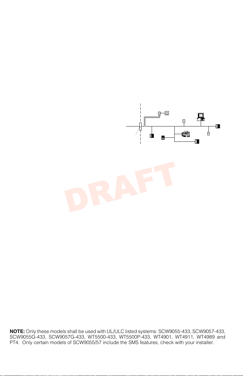
Alarm dialling equipment must be able to seize the telephone line and place a
call in an emergency situation. It must be able to do this even if other equi pment
(telephone, answering system, computer modem, etc.) alr eady has th e telephone
line in use. To do so, alarm dialling equipment must be connected to a properly
installed RJ-31X jack that is electrically in series with and ahead of all other
equipment attached to the same telephone line. Proper in stall ation is depict ed in
the figure below. If you have any questions concerning these instructions, you
should consult your telephone company or a qualified installer about installing
the RJ-31X jack and alarm dialling equipment for you.
INDUSTRY CANADA STATEMENT
NOTICE: This product meets the applicable Industry Canada technical specifications.
Le présent materiel est conforme aux specific ations techniq ues applica bles d’Industrie Canada.
The Ringer Equivalence Number (REN) for this terminal equipment is 0.1.
L'indice d'équivalence de la sonnerie (IES) du présent matériel est de 0.1.
The Ringer Equivalence Number is an indication of the maximum number of devices allowed to be connected to a telephone interface. The termination on an interface may consist of any combination of devices subject only to the requirement
that the sum of the RENs of all the devices does not exceed five.
L’indice d’équivalence de la sonnerie
(IES) sert à indiquer le nombre maximal de terminaux qui peuvent être raccordés
à une interface téléphonique. La terminaison d’une interface peut consister en une
combinaison quelconque de dispositifs, à la seule condition qu e la somm e d’indices d’équivalence de la sonnerie de tous les dispositifs n’excède pas 5.
The term ’IC:’ before the radio certification number only signifi es t hat Indust ry
Canada technical specifications were met.
Certification Number IC: 160A-9057 (models SCW9055-433/SCW9057-433)
Certification Number IC: 160A-9057G (models SCW9055(D)(G)(SM)-433/
SCW9057(D)(G)(SM)-433)
This Class B digital apparatus complies with Canadian ICES-003.
Cet appareil numérique de la classe B est conforme à la norme NMB-003 du
Canada.
The SCW9055(X)-433 and SCW9057(X)-433 have been investiga ted by UL a nd
ULC and found in compliance with the listing requirements for Re side nti al Fire
and Burglary applications in accordance with the follo wing s tand ards : UL985,
UL1023, UL1635, ULC-S545 and ORD-C1023.
This publication covers the following models:
• SCW9055-433/868 • SCW9055G-433/868 • SCW9055G-SM-433/868 • WT4901
• SCW9057-433/868 • SCW9057G-433/868 • SCW9057G-SM-433/868 • WT8901
• SCW9055D-433/868 • SCW9055D-SM-433/868 • WT5500-433/868 • WT4911
• SCW9057D-433/868 • SCW9057D-SM-433/868 • WT5500P-433/868 • WT8911
• SCW9055I-433/868 • SCW9055I-SM-433/868 • WT4989 • PT4
• SCW9057I-433/868 • SCW9057I-SM-433/868 • WT8989 • PT8
NOTE: The 868 MHz models are not UL/ULC listed.
NOTE: Only these models shall be used with UL/ULC listed systems: SCW9055-433, SCW9057-433,
SCW9055G-433, SCW9057G-433, WT5500-433, WT5500P-433, WT4901, WT4911, WT4989 and
PT4. Only certain models of SCW9055/57 include the SMS features, check with your installer.

About Your Security System 2
DRAFT
Fire Detection (must be enabled by Installer) . . . . . . . . . . . . . . . . . . . . . . . . . . . . . . . . . . . 2
Carbon Monoxide Detection (must be enabled by Installer) . . . . . . . . . . . . . . . . . . . . . . . . 2
Testing . . . . . . . . . . . . . . . . . . . . . . . . . . . . . . . . . . . . . . . . . . . . . . . . . . . . . . . . . . . . . . . . 2
Monitoring . . . . . . . . . . . . . . . . . . . . . . . . . . . . . . . . . . . . . . . . . . . . . . . . . . . . . . . . . . . . . . 2
Maintenance . . . . . . . . . . . . . . . . . . . . . . . . . . . . . . . . . . . . . . . . . . . . . . . . . . . . . . . . . . . . 2
General System Operation . . . . . . . . . . . . . . . . . . . . . . . . . . . . . . . . . . . . . . . . . . . . . . . . . 2
Keypad Controls & Indicators 3
Language Selection 3
Arming and Disarming the System 3
Stay Arming. . . . . . . . . . . . . . . . . . . . . . . . . . . . . . . . . . . . . . . . . . . . . . . . . . . . . . . . . . . . . 3
Night Arming . . . . . . . . . . . . . . . . . . . . . . . . . . . . . . . . . . . . . . . . . . . . . . . . . . . . . . . . . . . . 3
Silent Exit Delay . . . . . . . . . . . . . . . . . . . . . . . . . . . . . . . . . . . . . . . . . . . . . . . . . . . . . . . . . 4
Away Arming. . . . . . . . . . . . . . . . . . . . . . . . . . . . . . . . . . . . . . . . . . . . . . . . . . . . . . . . . . . . 4
Quick Exit . . . . . . . . . . . . . . . . . . . . . . . . . . . . . . . . . . . . . . . . . . . . . . . . . . . . . . . . . . . . . . 4
Siren Sounds After Away Arming . . . . . . . . . . . . . . . . . . . . . . . . . . . . . . . . . . . . . . . . . . . . 4
Disarming . . . . . . . . . . . . . . . . . . . . . . . . . . . . . . . . . . . . . . . . . . . . . . . . . . . . . . . . . . . . . . 4
Remote Arming and Disarming. . . . . . . . . . . . . . . . . . . . . . . . . . . . . . . . . . . . . . . . . . . . . . 5
Emergency Keys 5
When Alarm Sounds . . . . . . . . . . . . . . . . . . . . . . . . . . . . . . . . . . . . . . . . . . . . . . . . . . . . . . 5
Intrusion (Burglary) Alarm Continuous Siren. . . . . . . . . . . . . . . . . . . . . . . . . . . . . . . . . . . . 5
Fire Alarm Pulsed Siren 5
Carbon Monoxide Alarm (for future use, to be activated by your installer) 5
Audio Operation 5
2-Way/1-Way Audio Operation (SCW9057 only). . . . . . . . . . . . . . . . . . . . . . . . . . . . . . . . 5
Two-Way Audio Operation Over GSM (SCW9057G only) . . . . . . . . . . . . . . . . . . . . . . . . . 6
Time & Date Programming 6
Bypassing Zones 6
Trouble Conditions 7
Alarm Memory 8
Door Chime 8
Access Code Programming 8
Access Codes [][5][Master Code] (when disarmed) . . . . . . . . . . . . . . . . . . . . . . . . . . . . . 8
User Code Attributes. . . . . . . . . . . . . . . . . . . . . . . . . . . . . . . . . . . . . . . . . . . . . . . . . . . . . . 8
Inherent Attributes (all codes except installer) . . . . . . . . . . . . . . . . . . . . . . . . . . . . . . . . . . 8
Zone Bypassing Attribute . . . . . . . . . . . . . . . . . . . . . . . . . . . . . . . . . . . . . . . . . . . . . . . . . . 9
Remote Access Attribute. . . . . . . . . . . . . . . . . . . . . . . . . . . . . . . . . . . . . . . . . . . . . . . . . . . 9
Bell/Siren Squawk Attribute. . . . . . . . . . . . . . . . . . . . . . . . . . . . . . . . . . . . . . . . . . . . . . . . . 9
Erasing an Access Code. . . . . . . . . . . . . . . . . . . . . . . . . . . . . . . . . . . . . . . . . . . . . . . . . . . 9
Proximity Tag Enrollment (PT4/PT8) 9
User Function Commands 10
Changing Brightness/Contrast . . . . . . . . . . . . . . . . . . . . . . . . . . . . . . . . . . . . . . . . . . . . . 10
Ambient Light Sensor . . . . . . . . . . . . . . . . . . . . . . . . . . . . . . . . . . . . . . . . . . . . . . . . . . . . 11
Changing the Buzzer Level. . . . . . . . . . . . . . . . . . . . . . . . . . . . . . . . . . . . . . . . . . . . . . . . 11
Viewing the Event Buffer. . . . . . . . . . . . . . . . . . . . . . . . . . . . . . . . . . . . . . . . . . . . . . . . . . 11
Changing Voice Dialer and SMS Phone Numbers 11
Late to Open 12
SMS (Short Message Service) Notification 12
The SMS Notification Sequence. . . . . . . . . . . . . . . . . . . . . . . . . . . . . . . . . . . . . . . . . . . . 12
SMS Remote Access Connection Sequence . . . . . . . . . . . . . . . . . . . . . . . . . . . . . . . . . . 12
On-board LCD SMS Messages. . . . . . . . . . . . . . . . . . . . . . . . . . . . . . . . . . . . . . . . . . . . . . 12
Two-Way Wireless Key (WT4989, WT8989) 13
Function Keys . . . . . . . . . . . . . . . . . . . . . . . . . . . . . . . . . . . . . . . . . . . . . . . . . . . . . . . . . . 13
WT4989/WT8989 Status Display Icons . . . . . . . . . . . . . . . . . . . . . . . . . . . . . . . . . . . . . . 13
Buzzer. . . . . . . . . . . . . . . . . . . . . . . . . . . . . . . . . . . . . . . . . . . . . . . . . . . . . . . . . . . . . . . . 14
Keylock Mode . . . . . . . . . . . . . . . . . . . . . . . . . . . . . . . . . . . . . . . . . . . . . . . . . . . . . . . . . . 14
Testing Your System 14
Siren and Keypad Display Test. . . . . . . . . . . . . . . . . . . . . . . . . . . . . . . . . . . . . . . . . . . . . 14
Walk Test . . . . . . . . . . . . . . . . . . . . . . . . . . . . . . . . . . . . . . . . . . . . . . . . . . . . . . . . . . . . . 15
Allowing Computer Access to your System . . . . . . . . . . . . . . . . . . . . . . . . . . . . . . . . . . . 15
Reference Sheets 15
Access Codes . . . . . . . . . . . . . . . . . . . . . . . . . . . . . . . . . . . . . . . . . . . . . . . . . . . . . . . . . . 16
Sensor / Zone Information. . . . . . . . . . . . . . . . . . . . . . . . . . . . . . . . . . . . . . . . . . . . . . . . . 16
Voice Dialer and SMS Telephone Numbers . . . . . . . . . . . . . . . . . . . . . . . . . . . . . . . . . . . 16
Keypad Quick Guide 17
Guidelines for Locating Smoke & CO Detectors 18
Household Fire Safety Audit 21
Fire Escape Planning 21
i

Always ensure you obtain the latest version of the User Guide. Updated versions of this User
DRAFT
Guide are available by contacting your distributor.
IMPORTANT SAFETY INSTRUCTIONS
To reduce the risk of fire, electric shock and/or injury, observe the following:
• Do not spill any type of liquid on the equipment.
• Do not attempt to service this product yourself. Opening or removing the cover may expose you
to dangerous voltage or other risk. Refer servicing to qualified service personnel. Never open
the device yourself.
• Do not touch the equipment and its connected cables during an electrical storm; there may be
a risk of electric shock from lightning.
• Do not use the Alarm System to report a gas leak if the system is near a leak.
REGULAR MAINTENANCE AND TROUBLESHOOTING
Keep your Alarm Controller in optimal condition by following all the instructions that are included
within this manual and/or marked on the product.
CLEANING
• Clean the units by wiping with a damp cloth only.
• Do not use abrasives, thinners, solvents or aerosol cleaners (spray polish) that may enter
through holes in the Alarm Controller and cause damage.
• Do not use any water or any other liquid.
• Do not wipe the front cover with alcohol.
TROUBLESHOOTING
Occasionally, you may have a problem with your Alarm Controller or telephone line. If this happens, your Alarm Controller will identify the problem and display an error message. Refer to the
provided list when you see an error message on the display. If additional help is required, contact your distributor for service.
WAR NING: This equipment, Alarm System SCW9055/57 shall be installed and used within an
environment that provides the pollution degree max 2 and over-voltages category II non-hazardous locations, indoor only. It is designed to be installed, serviced and/or repaired by service persons only [service person is defined as a person having the appropriate technical training and
experience necessary to be aware of hazards to which that person may be exposed in performing a task and of measures to minimize the risks to that person or other persons]. For EU and
Australian markets, the equipment is permanently connected; an accessible disconnect device
shall be incorporated into the building installation wiring. For North America the equipment is
using a direct plug-in connection; the socket outlet shall be installed near the SCW9055/57 and
shall be easily accessible. The plug of the direct plug-in transformer serves as the disconnect
device.
NOTE: There are no parts replaceable by the end-user within this equipment, except for the
keypad batteries and the WT4901/8901, WT4989/8989 batteries.
WAR NING: Never obstruct the access to the socket-outlet to which this equipment is con-
nected. These safety instructions should not prevent you from contacting the distributor and/or
the manufacturer to obtain any further clarification and/or answers to your concerns.
1

About Your Security System
DRAFT
Read this manual carefully and have your installer instruct you on your system's operation and
on which features have been implemented in your system. All users of this system should be
fully instructed in its use. Fill out the "System Information" page with all of your zone information
and access codes, and store this manual in a safe place for future reference.
NOTE: Please consult your installer for further information regarding the false alarm reduction
features built into your system, as not all are covered in this manual.
Fire Detection (must be enabled by Installer)
This equipment is capable of monitoring fire detection devices such as smoke detectors and
providing a warning if a fire condition is detected. Good fire detection depends on having an
adequate number of detectors placed in appropriate locations. This equipment should be
installed in accordance with NFPA 72 (N.F.P.A., Batterymarch Park, Quincy MA 02269). Please
read the Family Escape Planning guidelines in this manual.
Carbon Monoxide Detection (must be enabled by Installer)
This equipment is capable of monitoring carbon monoxide detectors and providing a warning if
carbon monoxide is detected. Please read the Family Escape Planning guidelines in this manual and instructions that are available with the carbon monoxide detector.
Testing
To ensure that your system continues to function as intended, you must test your system weekly.
Please refer to the "Testing your System" section in this manual. If your system does not function
properly, call your installing company for service.
Monitoring
This system is capable of transmitting alarms, troubles, and emergency information to a central
station. If you initiate an alarm by mistake, immediately call the central station to prevent an
unnecessary response.
NOTE: The monitoring function must be enabled by the installer before it can become functional.
NOTE: This system has a communicator delay of 30 seconds. This function can be deleted, or
it can be increased up to a maximum of 45 seconds by the installer.
NOTE: Ensure that your installer verifies that your system is compatible with the Central Station
Receiver format at yearly intervals.
Maintenance
With normal use, the system requires minimum maintenance. Note the following points:
• Do not wash the security equipment with a wet cloth. Light dusting with a slightly moistened
cloth should remove normal accumulations of dust.
• Replace the standby battery every 3-5 years.
NOTE: Do not attempt to replace the battery or open the enclosure; there is a risk of electric
shock and/or fire.
• For other system devices such as smoke detectors, motion detectors, glassbreak detectors or
door/window contacts, consult the manufacturer’s literature for testing and maintenance
instructions.
General System Operation
Your security system comprises an integrated alarm control/keypad and various sensors and
detectors. The keypad is mounted by the main entry/exit location. The system is self-contained;
electronics and standby battery are housed within the keypad unit.
NOTE: Only the installer or service professional should have access to the system.
The security system has several zones of area protection. Each of these zones communicates
to a single wireless sensor (motion detectors, glassbreak detectors, door contacts, etc.) or to
one or more hard-wired sensors. A sensor in alarm is indicated by messages on the LCD.
Additional features include Automatic Inhibit (Swinger Shutdown) for Alarm; Tamper and Trouble
signals after 3 occurrences in a given set period; SMS interactive operation*; and a Programmable Keypad Lockout option.
For SIA CP-01 classified installations, the swinger shutdown feature is programmed such that
one or two trips will shut down the zone. The zone will be restored after a manual reset (by
2
entering the access code at the time of disarming the alarm system) or it will be reset automati-
Stay
Away
Chime
Bypass
Exit
3
6
9
#
2
5
8
0
1
4
7
*
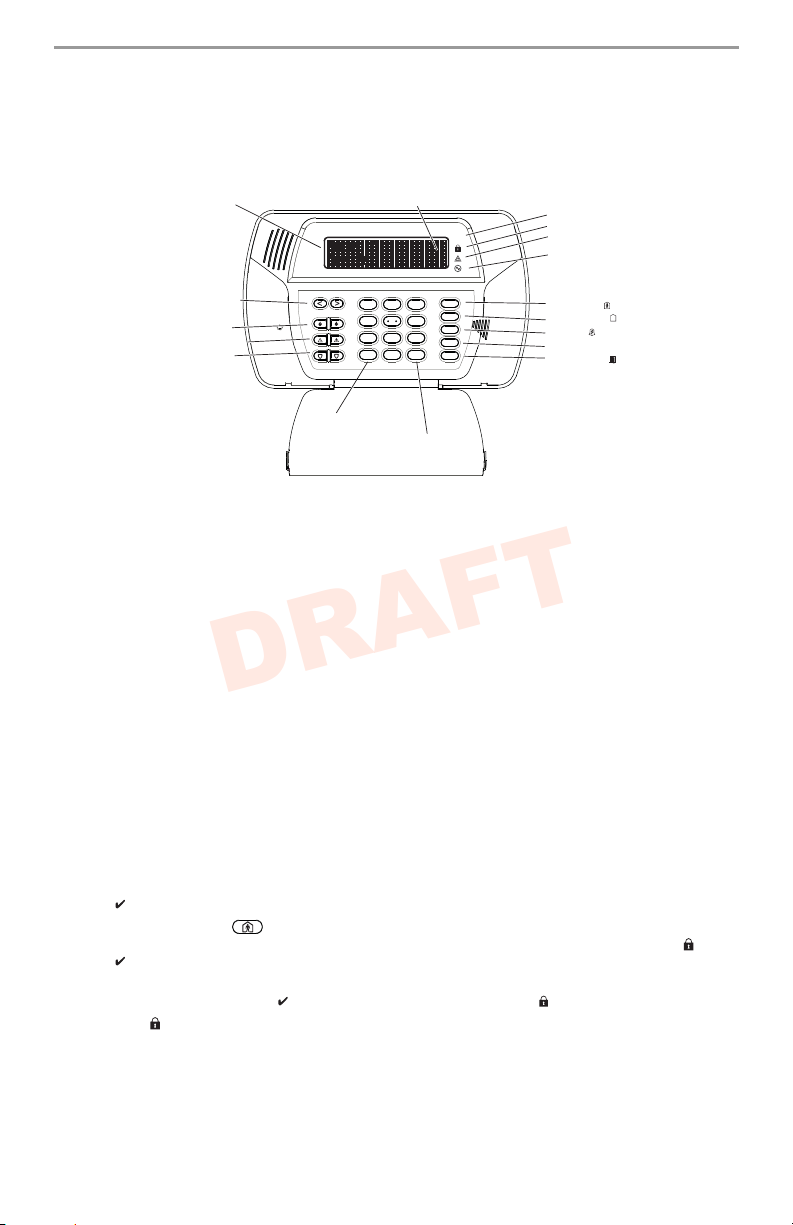
LED Indicators
Ready
Armed
Trouble
Power
Function Keys
Away
Arm
Stay
Arm
Chime
Bypass Zones
Quick Exit
X
O
Previous Screen
Selects Option
Scroll Keys
Fire Key
Auxiliary Key
Panic Key
2x16 LCD
<>indicates user can
scroll through options
DRAFT
cally after 48 hours with no trips on any zones.
NOTE: (*) The SMS features was not investigated by UL/ULC.
Keypad Controls & Indicators
IMPORTANT NOTICE
A security system cannot prevent emergencies. It is only intended to alert you and your central
station (if applicable) to an emergency situation. Security systems are generally very reliable
but they may not work under all conditions and they are not a substitute for prudent security
practices or life and property insurance. Your security system must be installed and serviced by
qualified security professionals. These professionals can instruct you on the level of protection
that has been provided and on system operations.
NOTE: When the keypad is in Sleep Mode it is saving battery life e.g., backlighting, LCD
message display will not be turned on until there is a specific reason: a key is pressed, entry
delay is started. In this mode the keypad is still functioning and nothing will be visible; however
if desired, your installer can enable the product to show the armed status while in Sleep Mode.
Language Selection
Your system can display messages in different languages.
1. Press and hold both [<][>] buttons simultaneously for 2 seconds.
2. Using the [<][>] buttons, scroll through the available languages.
3. Press [
] to select your desired language.
Arming and Disarming the System
Stay Arming
Stay arming will bypass the interior protection (i.e., motion sensors) and arm the perimeter of
the system (i.e., doors and windows). Close all sensors (i.e., stop motion and close doors). The
Ready ( ) indicator will illuminate.
Press and hold the Stay button until it beeps (approx. 2 seconds. Enter your access code,
do not leave the premises. During the setting state (Exit Delay active), the Armed ( ) and
Ready ( ) indicators will illuminate.
When the exit delay is completed, the alarm system is armed/set and this is indicated on the
keypad as follows: the Ready ( ) indicator will turn off, the Armed ( ) indicator will remain on.
The Armed ( ) indicator and a bypass message will be displayed. The system will automatically ignore bypassed zones (i.e., motion sensors).
NOTE: Your installer can program a function key on the keypad to allow you to arm the system
in Stay mode instantly. This allows you to activate Stay Arming by holding down the function key
for 2 seconds. The system arms immediately with no beeps sounding and no exit delay. This
feature must not be used in CP-01 installations.
3

NOTE: For SIA CP-01 listed panels, the Stay Arming Exit Delay will be twice as long as the Away
DRAFT
Arming Exit Delay.
NOTE: If your system is installed in accordance with SIA CP-01 Standard for False Alarm
Reduction, then the security system will arm in the Stay Armed mode if the exit delay time expires
and no exit has been made.
Night Arming
To night arm the system when it has been armed in Stay mode, press [][1] at the keypad. All
interior zones will now be armed except for devices programmed as Night zones.
NOTE: Your installer can also program a function key on the keypad to allow you to arm the
system in Night mode. This allows Night arming to be activated by holding down the function
key for 2 seconds.
Night zones are only armed in Away mode; this permits limited movement within the premises
when the system is fully armed. Ensure that your installer has provided you with a list identifying
zones programmed as night zones.
When the interior zones are activated (i.e., [
the system in order to gain access to interior areas that have not been programmed as night
zones.
][1]) you must enter your access code to disarm
Silent Exit Delay
If the system is armed using the Stay button or using the "No Entry" Arming method ([][9]
[Access Code]), the keypad buzzer will be silenced and the exit time will be doubled for that
exit period only. (CP-01 only)
Away Arming
Close all sensors (i.e., stop motion and close doors). The Ready ( ) indicator should be on.
To arm, press and hold the Away button for 2 seconds and/or enter your access code or press
][0] to Quick Arm.
[
During the setting state (exit delay active) the Armed ( ) and Ready ( ) indicators will turn on,
and the keypad will sound one beep per second. You now have ___ seconds to leave the premises (please check with your installer to have this time programmed). A keypad buzzer, whose
pulsating rate is distinct, will sound during the last ten seconds of the exit delay to warn person(s) that the exit delay is running out. To cancel the arming sequence, enter your access
code.
When the exit delay is completed, the alarm system is armed and this is indicated on the keypad display as follows: the Ready ( ) indicator will turn off, the Armed ( ) indicator will remain
on and the keypad will stop sounding.
NOTE: The system can also be armed/disarmed with a wireless key and with prox tags. Refer
to the "Proximity Tags" and "Two-Way Wireless Key" sections for more details.
NOTE: If your system is installed in accordance with SIA CP-01 Standard for False Alarm
Reduction, the following holds true: Violation and restoral, followed by a second violation of the
entry/exit zone before the end of the exit delay, will restart the exit delay.
Quick Exit
If the system is armed and you need to exit, use the Quick Exit function to avoid disarming and
rearming the system. Press and hold the Quick Exit button for 2 seconds or press [
You now have 2 minutes to leave the premises. When the door is closed again, the remaining
exit time is cancelled.
][0].
Siren Sounds After Away Arming
Audible Exit Fault
In order to reduce false alar
exit when arming the system. If you fail to securely close the entry/exit door during the programmed exit delay period, the system will sound the alarm to indicate an improper exit (your
installer will tell you if this feature has been enabled on your system). If this occurs:
1. Re-enter the premises.
2. Enter your access code before the entry delay timer expires, to disarm the system.
ms, the Audible Exit Fault is designed to notify you of an improper
4

3. Repeat the Away arming procedure, ensuring that the entry/exit door(s) are secured.
DRAFT
Arming Error
An error tone will sound if the system is unable to arm. This will happen if the system is not ready
to arm (i.e., sensors are open), or if an incorrect user code has been entered. If this happens,
ensure all sensors are secure, press [#] and try again.
Disarming
To disarm an armed system (Armed ( ) indicator is On), enter your access code. If your keypad is in sleep mode, press any key to wake it up then enter your access code. The keypad will
sound a continuous tone after the entry delay has been initiated by opening the entry/exit door.
Enter your code within _______ seconds to avoid an alarm condition (check with your installer to
have this time programmed).
Disarming Error
If your code is invalid, the system will not disarm and a 2-second error tone will sound. If this
happens, press [#] and try again.
Remote Arming and Disarming
The system can be armed and/or disarmed, if programmed by the installer, using a remote control
device (wireless key). When arming the system using the Arm button on a wireless key, the system
will acknowledge the command by sounding a single bell/siren squawk, if programmed to do so by
the installer. When disarming using the Disarm button on a wireless key, the system will acknowledge the command by sounding two bell/siren squawks. Three squawks, when disarming with the
Disarm button, indicates that an alarm occurred while the system was armed. If you are unsure of
the cause of the alarm, proceed with caution (see section on 2-way Wireless Keys).
Emergency Keys
Press BOTH (Fire), (Auxiliary), or (Panic) buttons for 2 seconds to generate a
Fire, Auxiliary, or Panic alarm. The keypad buzzer will beep indicating that the alarm input has
been accepted and transmission to the central station is underway. The Fire buttons may or may
not sound the siren depending on installer setup.
NOTE: The Fire button can be disabled by the installer.
NOTE: The Auxiliary Alarm button is not intended to be used for medical signals.
When Alarm Sounds
The system can generate 3 different alarm sounds:
• Continuous Siren = Intrusion/Burglary Alarm
NOTE: The WT4911 siren will sound a dual frequency sweeping tone for burglary alarms.
• Temporal / Pulsed Siren = Fire Alarm
• 4 beeps, 5-second pause, 4 beeps = Carbon Monoxide alarm
NOTE: The priority of signals is fire alarm, carbon monoxide alarm then burglary alarm.
Intrusion (Burglary) Alarm Continuous Siren
If you are unsure of the source of the alarm, proceed with caution! If the alarm was acciden-
tal, enter your access code to silence the alarm. If the alarm system is disarmed within the programmed Abort Window (check with the installer if this option has been enabled on your system
and what is the transmitter delay time programmed), no alarm transmission to the Central Station
will occur. Following the Abort Window there appears a 5-minute Cancel Window, during which
a user can cancel, by entering their access code, an alarm that has been previously transmitted.
A cancel signal will be transmitted to the central station and the alarm system will also announce
that the cancel signal was transmitted. Call your central station to avoid a dispatch.
Fire Alarm Pulsed Siren
Follow your emergency evacuation plan immediately!
If the fire alarm was accidental (burned toast, bathroom steam, etc.), enter your access code to
silence the alarm. Call your central station to avoid a dispatch.
Carbon Monoxide Alarm (must be enabled by your installer)
Activation of your CO alarm indicates the presence of carbon monoxide (CO), which can be
fatal. During an alarm, the red LED on the CO detector flashes rapidly and buzzer sounds with a
repeating cadence of: 4 quick beeps, 5-second pause, 4 quick beeps. If an alarm sounds:
5

1. Operate silence button.
HH:MM MM/DD/YY
09:06 01/31/10
Press (*) for <>
Zone Bypass
Enter Your
Access Code
Scroll to <>
Bypass Zones
DRAFT
2. Call emergency services or your fire department.
3. Immediately move outdoors or to an open door/window.
WARNING: Carefully review your Carbon Monoxide Installation/User Guide to determine the
necessary actions required to ensure your safety and ensure that the equipment is operating correctly. Incorporate the steps outlined in the guide into your evacuation plan.
2-Way/1-Way Audio Operation (SCW9057 only)
If programmed by the installer, this feature allows the monitoring station to initiate a 2-way audio
(talk/listen) or 1-way audio (listen-in only) session when an alarm has been received. This feature is
used to verify the nature of the alarm or determine the type of assistance required by the occupant.
NOTE: This feature can be initiated only by the monitoring station after an alarm has been
received. The user can not initiate a 2-way audio session.
Time & Date Programming and Temperature Display
Press [][6] then enter your master access code to enter
User Functions. Use the [<][>] buttons to find the menu
option, then press [
exit programming. If you are viewing a "Loss of Clock" trouble from within the trouble menu
([
][2]), press [] to directly enter Date and Time programming (see Trouble Conditions).
The SCW9055/57 panel and WT5500 keypad can also display the outdoor temperature (Farenheit or Celsius) from the 2-way outdoor siren. This feature must be enabled by your installer.
NOTE: Your installer may have programmed your system to display the time and date while the
keypad is idle. Press the [#] button to temporarily clear the date and time display if desired.
mat (HH:MM), followed by the date (MM:DD:YY). Press [#] to
] to select. Enter the time in 24-hr. for-
Bypassing Zones
Use the zone bypassing feature when you need access to a protected area while the system is
armed, or when a zone is temporarily out of service but you need to arm the system. Bypassed
zones will not be able to sound an alarm. As a result, bypassing zones reduces the level of
security. If you are bypassing a zone because it is not working, call a service technician immediately so that the problem can be resolved and your system returned to proper working order.
Ensure that no zones are unintentionally bypassed when arming your system. Zones cannot be
bypassed once the system is armed. Bypassed zones (except for 24-hr zones) are automatically cancelled each time the system is disarmed and must be bypassed again, if required,
before the next arming.
With the system disarmed:
1. Press [
2. Press [1] or [
3. If your system is programmed to require access codes the screen
4. Scroll to the desired zone number using the [<][>] keys, then
] to enter the function menu. The keypad will display the
screen on the right.
].
on the right will be displayed. Enter your 4-digit access code.
] to select the zone or directly enter the 2-digit number of
press [
the zone you wish to bypass (e.g., 0 5 for zone 5).
Activating All Bypassed Zones
To remove bypass (all zones):
1. Press [
2. Press [0][0].
3. To exit bypassing mode and return to the Ready state, press [#].
Recalling Bypassed Zones
To recall the last set of bypassed zones:
1. Press [
2. Press [9][9].
][1], then your access code.
][1], then your access code.
6
 Loading...