

Tyco Safety Canada 10GS260LSM Users manual

Alarm
Communicator
GS2060-RS
GPRS/GSM Wireless Communica tor
TL260-RS
Ethernet/Internet Communicator
TL260GS-RS
Ethernet/Internet and GPRS/GSM Dual-Path Communicator
Installation Manual
Warning: This manual contains information on limitations regarding product use and function and
information on the limitations as to liability of the manufacturer.
v2.0


TABLE OF CONTENTS
GENERAL . . . . . . . . . . . . . . . . . . . . . . . . . . . . . . . . . . . . . . . . . . . . . . . . . . . . . . . . . . . . . . . . . . . . . . . . . . . . . . . . . . . 3
Panel Mounting . . . . . . . . . . . . . . . . . . . . . . . . . . . . . . . . . . . . . . . . . . . . . . . . . . . . . . . . . . . . . . . . . . . . . . . . . . . . . . . . . . . . . . 3
Features . . . . . . . . . . . . . . . . . . . . . . . . . . . . . . . . . . . . . . . . . . . . . . . . . . . . . . . . . . . . . . . . . . . . . . . . . . . . . . . . . . . . . . . . . . . 3
Technical Specifications . . . . . . . . . . . . . . . . . . . . . . . . . . . . . . . . . . . . . . . . . . . . . . . . . . . . . . . . . . . . . . . . . . . . . . . . . . . . . . . 3
UL/ULC Installation Requirements . . . . . . . . . . . . . . . . . . . . . . . . . . . . . . . . . . . . . . . . . . . . . . . . . . . . . . . . . . . . . . . . . . . . . . . 3
RatingsCompatibility . . . . . . . . . . . . . . . . . . . . . . . . . . . . . . . . . . . . . . . . . . . . . . . . . . . . . . . . . . . . . . . . . . . . . . . . . . . . . . . . . . 4
RatingsCompatibility . . . . . . . . . . . . . . . . . . . . . . . . . . . . . . . . . . . . . . . . . . . . . . . . . . . . . . . . . . . . . . . . . . . . . . . . . . . . . . . . . . 4
Pre Installation Configuration . . . . . . . . . . . . . . . . . . . . . . . . . . . . . . . . . . . . . . . . . . . . . . . . . . . . . . . . . . . . . . . . . . . 5
Encryption . . . . . . . . . . . . . . . . . . . . . . . . . . . . . . . . . . . . . . . . . . . . . . . . . . . . . . . . . . . . . . . . . . . . . . . . . . . . . . . . . . . . . . . . . . 5
Communicator Pre Installation Configuration . . . . . . . . . . . . . . . . . . . . . . . . . . . . . . . . . . . . . . . . . . . . . . . . . . . . . . 5
Running the Ethernet Cable . . . . . . . . . . . . . . . . . . . . . . . . . . . . . . . . . . . . . . . . . . . . . . . . . . . . . . . . . . . . . . . . . . . . . . . . . . . . 5
Running the RS-232 Cable . . . . . . . . . . . . . . . . . . . . . . . . . . . . . . . . . . . . . . . . . . . . . . . . . . . . . . . . . . . . . . . . . . . . . . . . . . . . . 5
Installing the GSM/ETHERNET Communicator in PANEL. . . . . . . . . . . . . . . . . . . . . . . . . . . . . . . . . . . . . . . . . . . . . 6
Installing Communicator with PC1616/1832/1864 Panel . . . . . . . . . . . . . . . . . . . . . . . . . . . . . . . . . . . . . . . . . . . . . . . . . . . . . . 6
Initial Panel Programming . . . . . . . . . . . . . . . . . . . . . . . . . . . . . . . . . . . . . . . . . . . . . . . . . . . . . . . . . . . . . . . . . . . . . . 9
Keypad Data Display. . . . . . . . . . . . . . . . . . . . . . . . . . . . . . . . . . . . . . . . . . . . . . . . . . . . . . . . . . . . . . . . . . . . . . . . . . . . . . . . . . 9
Entering HEX values at keypad. . . . . . . . . . . . . . . . . . . . . . . . . . . . . . . . . . . . . . . . . . . . . . . . . . . . . . . . . . . . . . . . . . . . . . . . . . 9
Entering ASCII Characters at keypad. . . . . . . . . . . . . . . . . . . . . . . . . . . . . . . . . . . . . . . . . . . . . . . . . . . . . . . . . . . . . . . . . . . . . 9
PC1616/1832/1864 Initial Programming. . . . . . . . . . . . . . . . . . . . . . . . . . . . . . . . . . . . . . . . . . . . . . . . . . . . . . . . . . . . . . . . . . . 9
Communicator Troubles displayed on a PC1616/1832/1864 . . . . . . . . . . . . . . . . . . . . . . . . . . . . . . . . . . . . . . . . . . . . . . . . . . . 9
Communicator Placement Test . . . . . . . . . . . . . . . . . . . . . . . . . . . . . . . . . . . . . . . . . . . . . . . . . . . . . . . . . . . . . . . . . 10
Communicator Status LEDs. . . . . . . . . . . . . . . . . . . . . . . . . . . . . . . . . . . . . . . . . . . . . . . . . . . . . . . . . . . . . . . . . . . . 10
Yellow Trouble LED. . . . . . . . . . . . . . . . . . . . . . . . . . . . . . . . . . . . . . . . . . . . . . . . . . . . . . . . . . . . . . . . . . . . . . . . . . . . . . . . . . 10
Red Network Connection Status LED. . . . . . . . . . . . . . . . . . . . . . . . . . . . . . . . . . . . . . . . . . . . . . . . . . . . . . . . . . . . . . . . . . . . 11
(Green LED 1) (Green LED 2) and (Yellow LED) Signal Strength. . . . . . . . . . . . . . . . . . . . . . . . . . . . . . . . . . . . . . . . . . . . . . 11
Communicator Reset / Update. . . . . . . . . . . . . . . . . . . . . . . . . . . . . . . . . . . . . . . . . . . . . . . . . . . . . . . . . . . . . . . . . . 12
Factory Defaults Reset . . . . . . . . . . . . . . . . . . . . . . . . . . . . . . . . . . . . . . . . . . . . . . . . . . . . . . . . . . . . . . . . . . . . . . . . . . . . . . . 12
Firmware Update. . . . . . . . . . . . . . . . . . . . . . . . . . . . . . . . . . . . . . . . . . . . . . . . . . . . . . . . . . . . . . . . . . . . . . . . . . . . . . . . . . . . 12
Communicator Reset / Update . . . . . . . . . . . . . . . . . . . . . . . . . . . . . . . . . . . . . . . . . . . . . . . . . . . . . . . . . . . . . . . . . . . . . . . . . . . 12
Appendix A: Communicator Troubleshooting . . . . . . . . . . . . . . . . . . . . . . . . . . . . . . . . . . . . . . . . . . . . . . . . . . . . . 13
ETHERNET/GPRS PROGRAMMING SECTIONS. . . . . . . . . . . . . . . . . . . . . . . . . . . . . . . . . . . . . . . . . . . . . . . . . . . . 14
System Options. . . . . . . . . . . . . . . . . . . . . . . . . . . . . . . . . . . . . . . . . . . . . . . . . . . . . . . . . . . . . . . . . . . . . . . . . . . . . . . . . . . . . 14
Programming Options . . . . . . . . . . . . . . . . . . . . . . . . . . . . . . . . . . . . . . . . . . . . . . . . . . . . . . . . . . . . . . . . . . . . . . . . . . . . . . . . 16
Communications Reporting Codes . . . . . . . . . . . . . . . . . . . . . . . . . . . . . . . . . . . . . . . . . . . . . . . . . . . . . . . . . . . . . . . . . . . . . . 18
System Test Options [026 - 029]. . . . . . . . . . . . . . . . . . . . . . . . . . . . . . . . . . . . . . . . . . . . . . . . . . . . . . . . . . . . . . . . . . . . . . . . 19
Ethernet Receiver 1 Options. . . . . . . . . . . . . . . . . . . . . . . . . . . . . . . . . . . . . . . . . . . . . . . . . . . . . . . . . . . . . . . . . . . . . . . . . . . 19
Ethernet Receiver 2 Options. . . . . . . . . . . . . . . . . . . . . . . . . . . . . . . . . . . . . . . . . . . . . . . . . . . . . . . . . . . . . . . . . . . . . . . . . . . 20
Ethernet Options . . . . . . . . . . . . . . . . . . . . . . . . . . . . . . . . . . . . . . . . . . . . . . . . . . . . . . . . . . . . . . . . . . . . . . . . . . . . . . . . . . . . 21
GPRS Receiver 1 Options. . . . . . . . . . . . . . . . . . . . . . . . . . . . . . . . . . . . . . . . . . . . . . . . . . . . . . . . . . . . . . . . . . . . . . . . . . . . . 21
GPRS Receiver 2 Options. . . . . . . . . . . . . . . . . . . . . . . . . . . . . . . . . . . . . . . . . . . . . . . . . . . . . . . . . . . . . . . . . . . . . . . . . . . . . 21
GPRS Options. . . . . . . . . . . . . . . . . . . . . . . . . . . . . . . . . . . . . . . . . . . . . . . . . . . . . . . . . . . . . . . . . . . . . . . . . . . . . . . . . . . . . . 22
Interactive Options . . . . . . . . . . . . . . . . . . . . . . . . . . . . . . . . . . . . . . . . . . . . . . . . . . . . . . . . . . . . . . . . . . . . . . . . . . . . . . . . . . 22
System Information (Read Only). . . . . . . . . . . . . . . . . . . . . . . . . . . . . . . . . . . . . . . . . . . . . . . . . . . . . . . . . . . . . . . . . . . . . . . . 26
System Reset Defaults . . . . . . . . . . . . . . . . . . . . . . . . . . . . . . . . . . . . . . . . . . . . . . . . . . . . . . . . . . . . . . . . . . . . . . . . . . . . . . . 26
ETHERNET/GPRS PROGRAMMING WORKSHEETS . . . . . . . . . . . . . . . . . . . . . . . . . . . . . . . . . . . . . . . . . . . . . . . . 27
System Options. . . . . . . . . . . . . . . . . . . . . . . . . . . . . . . . . . . . . . . . . . . . . . . . . . . . . . . . . . . . . . . . . . . . . . . . . . . . . . . . . . . . . 27
Programming Options . . . . . . . . . . . . . . . . . . . . . . . . . . . . . . . . . . . . . . . . . . . . . . . . . . . . . . . . . . . . . . . . . . . . . . . . . . . . . . . . 27
System Test Options [026 - 029]. . . . . . . . . . . . . . . . . . . . . . . . . . . . . . . . . . . . . . . . . . . . . . . . . . . . . . . . . . . . . . . . . . . . . . . . 27
Ethernet Receiver 1 Options. . . . . . . . . . . . . . . . . . . . . . . . . . . . . . . . . . . . . . . . . . . . . . . . . . . . . . . . . . . . . . . . . . . . . . . . . . . 27
Ethernet Receiver 2 Options. . . . . . . . . . . . . . . . . . . . . . . . . . . . . . . . . . . . . . . . . . . . . . . . . . . . . . . . . . . . . . . . . . . . . . . . . . . 28
Ethernet Options . . . . . . . . . . . . . . . . . . . . . . . . . . . . . . . . . . . . . . . . . . . . . . . . . . . . . . . . . . . . . . . . . . . . . . . . . . . . . . . . . . . . 28
GPRS Receiver 1 Options. . . . . . . . . . . . . . . . . . . . . . . . . . . . . . . . . . . . . . . . . . . . . . . . . . . . . . . . . . . . . . . . . . . . . . . . . . . . . 28
GPRS Receiver 2 Options. . . . . . . . . . . . . . . . . . . . . . . . . . . . . . . . . . . . . . . . . . . . . . . . . . . . . . . . . . . . . . . . . . . . . . . . . . . . . 28
GPRS Options. . . . . . . . . . . . . . . . . . . . . . . . . . . . . . . . . . . . . . . . . . . . . . . . . . . . . . . . . . . . . . . . . . . . . . . . . . . . . . . . . . . . . . 28
Interactive Options . . . . . . . . . . . . . . . . . . . . . . . . . . . . . . . . . . . . . . . . . . . . . . . . . . . . . . . . . . . . . . . . . . . . . . . . . . . . . . . . . . 29
System Information (Read Only). . . . . . . . . . . . . . . . . . . . . . . . . . . . . . . . . . . . . . . . . . . . . . . . . . . . . . . . . . . . . . . . . . . . . . . . 30
System Reset Defaults . . . . . . . . . . . . . . . . . . . . . . . . . . . . . . . . . . . . . . . . . . . . . . . . . . . . . . . . . . . . . . . . . . . . . . . . . . . . . . . 30
End User Licence Agreement . . . . . . . . . . . . . . . . . . . . . . . . . . . . . . . . . . . . . . . . . . . . . . . . . . . . . . . . . . . . . . . . . . 31
Limited Warranty. . . . . . . . . . . . . . . . . . . . . . . . . . . . . . . . . . . . . . . . . . . . . . . . . . . . . . . . . . . . . . . . . . . . . . . . . . . . . . 32
1

WARNING Please Read Carefully
This
Warn ing
installer’s respon sibility to br ing ea ch ite m in this
System Failures
This system has been carefully designed to be as effective as
possible. There are circumstances, however, involving fire, burglary, or other types of emergencies where it may not provide
protection. Any alarm system of any type may be compromised
deliberately or may fail to operate as expected for a variety of
reasons. Some but not all of these reasons may be:
Access by Intruders
Intruders may enter through an unprotected access point, circumvent a sensing device, evade detection by moving through
an area of insufficient coverage, disconnect a warning device, o r
interfere with or prevent the proper operation of the system.
Component Failure
Although every effort has been made to make this system as
reliable as possible, the system may fail to function as intended
due to the failure of a component.
Compromise of Radio Frequency (Wireless) D evices
Signals may not reach the receiver under all circumstances
which could include metal objects placed on or near the radio
path or deliberate jamming or other inadvertent radio signal
interference.
Criminal Knowledge
This system contains security features which were known to be
effective at the time of manufacture. It is possible for persons
with criminal intent to develop techniques which reduce the
effectiveness of these features. It is important that your security
system be reviewed periodically to ensure that its features
remain effective and that it is updated or replaced if it is found
that it does not provide the protection expected.
Failure of Replaceab le Batte ries
This system’s wireless transmitters have been designed to provide several years of battery life under normal conditions. The
expected battery life is a function of the device environment,
usage, and type. Ambient conditions such as high humidity, high
or low temperatures, or large temperature fluctuations may
reduce the expected battery life. While each transmitting device
has a low battery monitor which identifies when the batteries
need to be replaced, this monitor may fail to operate as
expected. Regular testing and m aintenance will ke ep the system
in good operating condition.
Inadequate Installa tion
A security system must be installed properly in order to provide
adequate protection. Every installation should be evaluated by a
security professional to ensure that all access points and areas
are covered. Locks and latches on windows and doors must be
secure and operate as intended. Windows, doors, walls, ceilings
and other building materials must be of sufficient strength and
construction to provide the level of protection expected. A
reevaluation must be done during and after any construction
activity. An evaluation by the fire and/or police department is
highly recommended if this service is available.
Inadequate Testing
Most problems that would prevent an alarm system from operating as intended can be found by regular testing and maintenance. The complete system should be tested weekly and
immediately after a break-in, an attempted break-in, a fire, a
storm, an earthquake, an accident, or any kind of construction
activity inside or outside the premises. The testing should
include all sensing devices, keypads, consoles, alarm indicating
devices, and any other operational devices that are part of the
system.
Insufficient T ime
There may be circumstances when the system will operate as
intended, yet the occupants will not be protected from an emergency due to their inability to respond to the warnings in a timely
manner. If the system is remotely monitored, the response may
not occur in time to protect the occupants or their belongings.
contains vital information. As the only individual in contact with system users, it is the
Note to Installers
Warn ing
to the attention of all users of this system.
Motion Detectors
Motion detectors can only detect motion within the designated
areas as shown in their respective installation instructions. They
cannot discriminate between intruders and intended occupants.
Motion detectors do not provide volumetric area protection. They
have multiple beams of detection and motion can only be
detected in unobstructed areas covered by these beams. They
cannot detect motion which occurs behind walls, ceilings, floor,
closed doors, glass partitions, glass doors or windows. Any type
of tampering whether intentional or unintentional such as masking, painting, or spraying of any material on the lenses, mirrors,
windows or any other part of the detection system will impair its
proper operation.
Passive infrared motion detectors operate by sensing changes
in temperature. However their effectiveness can be reduced
when the ambient temperature rises near or above body temperature or if there are intentional or unintentional sources of
heat in or near the detection area. Some of these heat sources
could be heaters, radiators, stoves, barbeques, fireplaces, sunlight, steam vents, lighting, and so on.
Power Failure
Control units, intrusion detectors, smoke detectors and many
other security devices require an adequate power supply for
proper operation. If a device operates from batteries, it is possible for the batteries to fail. Even if the batteries have not failed,
they must be charged, in good condition and installed correctly. If
a device operates only by AC power, any interruption, however
brief, will render that device inoperative while it does not have
power. Power interruptions of any length are often accomp anied
by voltage fluctuations which may damage electronic equipment
such as a security system. After a power interruption has
occurred, immediately conduct a complete system test to ensure
that the system operates as intended.
Security and Insurance
Regardless of its capabilities, an alarm system is not a substitute
for property or life insurance. An alarm system also is not a substitute for property owners, renters, or other occupants to act
prudently to prevent or minimize the harmful effects of an emergency situation.
Smoke Detectors
Smoke detectors that are a part of this system may not properly
alert occupants of a fire for a number of reasons, some of which
follow. The smoke detectors may ha ve been improperly installed
or positioned. Smoke may not be able to reach the smoke
detectors, such as when the fire is in a chimney, walls or roofs, or
on the other side of closed doors. Smoke detectors may not
detect smoke from fires on another level of the residence or
building.
Every fire is different in the amount of smoke produced and the
rate of burning. Smoke detectors cannot sense all types of fires
equally well. Smoke detectors may not provide timely warning of
fires caused by carelessness or safety hazards such as smoking
in bed, violent explosions, escaping gas, improper storage of
flammable materials, overloaded electrical circuits, children playing with matches or arson.
Even if the smoke detector operates as intended, there may be
circumstances when there is insufficient warning to allow all
occupants to escape in time to avoid injury or death.
Telephone Lines
If telephone lines are used to transmit alarms, they may be out of
service or busy for certain periods of time. Also an intruder may
cut the telephone line or defeat its operation by more sophisticated means which may be difficult to detect.
Warning Devices
Warning devices such as sirens, bells, horns, or strobes may not
warn people or waken someone sleeping if there is an intervening wall or door. If warning devices are located on a different
level of the residence or premise, then it is less likely that the
occupants will be alerted or awakened. Audible warning devices
may be interfered with by other noise sources such as stereos,
radios, televisions, air conditioners or other appliances, or passing traffic. Audible warning devices, however loud, may not be
heard by a hearing-impaired person.
2

GENERAL
IMPORTANT
This Installation Manual shall be used in conjunction with the Alarm controller Power Panel manual; All the
safety instructions specified within that manual shall be observed. (or equivalent). The alarm controller Power
Panel is referenced as “panel” throughout this document.
The GPRS/Ethernet Communicator is fixed, wall-mounted unit and shall be installed in the location specified in
these instructions. The equipment enclosure must be fully assembled and closed, with all the necessary
screws/tabs and secured to a wall before operation. Internal wiring must be routed in a manner that prevents:
• Excessive strain on wire and on terminal connections,
• Interference between power limited and non power limited wiring,
• Loosening of terminal; connections, or
• Damage of conductor insulation.
WARNING: Never install this equipment during a lightning storm!
Safety Information
The Installer must instruct the System user on each of the following:
• Do not attempt to service this product. Opening or removing covers may expose the user to dangerous
voltages or other risks.
• Any servicing shall be referred to trained service personnel only.
• Use authorized accessories only with this equipment.
Do not stay close to the equipment during device operation and to do not touch the antenna,
Model Information
GS2060-RS: Is a General Packet Radio Service/Global System for Mobile (GPRS/GSM) wireless alarm Com-
municators that send alarm communication to Sur-Gard System I, II, III (SG-DRL3IP), and IV (SG-DRL4IP)
central station receivers via a GPRS/GSM digital cellular network.
TL260-RS: Is an Ethernet alarm Communicator that send alarm co mmunication to Su r-Gard Sy stem I, II, a nd III
central station receivers through Ethernet/Internet connection.
TL260GS-RS
System I, II, III, and IV central station receivers through Ethernet/Internet or a GPRS/GSM digital cellular network.
The Communicator can be used as either a backup or primary Communicator. The Communicator supports Internet
Protocol (IP) transmission of panel and Communicator Events over Ethernet/Internet and/or GPRS/GSM.
The GPRS/GSM performance of the GS2060-RS and TL260GS-RS Communicators depends greatly on GSM
network coverage. The unit should not be mounted in the final location without first perf orming t he Commu nicator Placement Test on page 10 to determine the best location for radio reception (minimum of one green LED
ON). Optional antenna kits are available from DSC at: http://www.DSC.com.
NOTE: Prior to installation of the GS2060-RS/TL260GS-RS Communicator, confirm with your carrier
that the GPRS/GSM network is available and active in the area where the Communicator will be
installed and that radio signal strength (CSQ) is adequate.
Panel Mounting
The following Communicators are compatible with PC1616/PC1832/PC1864:
• GS2060-RS (GPRS/GSM only)
• TL260-RS (Ethernet/Internet only)
• TL260GS-RS (Ethernet/Internet + GPRS/GSM dual-path)
Features
• 128-bit AES encryption via GPRS/GSM and Ethernet/Internet (NIST Validation Certificate No. 995).
• Back up or primary GPRS/GSM alarm communication.
• Ethernet LAN/WAN 10/100 BaseT (TL260-RS/TL260GS-RS only).
• Full event reporting to central station (UL/ULC Listed), and external equipment via RS-232 (UL/ULC Listed) .
• Fully redundant Ethernet/Internet and GPRS/GSM Dual-path Alarm Communication (TL260GS-RS only).
• Individual Ethernet and/or GPRS Periodic test transmission.
• Integrated call routing.
• Panel remote uploading/downloading support via GPRS/GSM and Ethernet/Internet.
• PC-LINK connection.
• Programmable Lab els
• Quad-Band Operation: 850 MHz, 900 MHz, 1800 MHz, and 1900 MHz.
• RS-232 unbalanced line communication to customer furnished equipment up to 50 ft. (16 m).
• SIA and Contact ID (CID) formats supported.
• Signal strength and Trouble display LEDs.
• Subscriber Identity Module (SIM) card included with Communicator.
• Supervision heartbeats via GPRS/GSM and Ethernet/Internet.
Technical Specifications
The input voltage to the Communicator can be drawn from the Underwrite rs Laboratories/Underwriters Laboratories Canada (UL/ULC) Listed Control Panel or provided by an external UL/ULC Listed power supply rated for
the application (external power-limited source).
NOTE: The power supply must be Class II, Power Limited.
UL/ULC Installation Requirements
NOTE: For equipment used at the protected premises and intended to facilitate IP communications (hubs,
routers, Network Interface Device ( NID)s, Digital Subscriber Line (DSL /Cable modems) 24 hour back-up
power is required. Where such cannot be facilitated, a secondary (back-up) communi cation channel is
required. Programming for Domain Name Service (DNS) is not permitted in UL/ULC Listed systems.
: Is a Dual-path GSM/Ethernet alarm Communicators that send alarm communication to Sur-Gard
3
Notes for using Private, Corporate, and High Speed Data Networks:
Network access and domain access policies shall be set to restrict unauthorized network access, and spoofing
or Denial of Service (DoS) attacks. Select an Internet Service Provider (ISP) that has redundant servers/systems, back-up power, routers with firewalls enabled, and methods to identify and protect against DoS attacks
(e.g., via spoofing).
Notes for using Public Switched and Wireless Data Networks:
Communication channels shall be facilitated such that the Communicator will restrict unauthorized access,
which could otherwise compromise security. Communicators shall be located in secured areas.
• For ULC Residential fire and burglary applications the TL260GS-RS can be used as primary communication
channel via either GSM or Ethernet or as a back-up in conjunction with the Digital Alarm Communicator
Transmitter (DACT). Test transmission every 24hours shall be enabled on each channel.
• For ULC Commercial Fire and Burglary applications the GS2060-RS/TL260GS-RS can be used as a passive
communication module with the following Security Levels:
• P1 (each channel GSM or Ethernet is independent),
• P2 (GSM and Ethernet in back-up configuration, panel Section [851][005] Toggle Option [5] OFF),
• P3 (GSM and Ethernet in redundant configuration, panel Section [851][005] Toggle Option [5] ON).
• The module can be also used as an Active communication system with the Security Levels A1-A4 (each
channel GSM or Ethernet independent or together in a back-up/redundant configuration). For Active Line
Security systems AES128 bit encryption shall be enabled at the monitoring station receiver and the supervision heartbeat rate shall be set as 90 seconds (panel Section [851] [004] = 005A/90). The supervision window at the Signal Receiver Centre (SRC)'s receiver shall be programmed as maximum 00B4/180 seconds.
• For UL Residential fire and burglary applications the GS2060-RS andTL260GS-RS can be used as primary
communication channel via either GSM or Ethernet, or as a back-up in conjunction with the DACT (30 day
test transmission is required on each channel).
• For UL Commercial Burglary applications the TL260GS-RS module can be used as Dual Signalling Line
communication system (GSM and Ethernet channels used in redundant configuration), Standard Line Security and as Encrypted Line Security.
• The supervision heartbeat shall be enabled (panel Section [851] [005] Toggle Option [1] (Ethernet) and/or
Toggle Option [2] (GSM) shall be ON), Toggle Option [3] (Supervision Type) shall be ON and the supervision
heartbeat rate shall be selected as 0087/135 seconds Option [004] = 0087. The supervision window at the
supervising station shall be maximum 00C8/200 seconds. For Encrypted Line Security systems the encryption AES128 bit shall be enabled at the monitoring station receiver.
• For UL Commercial Burglary installations, the GS2060-RS is listed as a primary (sole) communication
means (heartbeat must be enabled) or for supplement ary (back-up) use in conjunction with a Plain Old Telephone Service (POTS) line (dialer). When the heartbeat transmission over the Ethernet or GPRS/GSM network is enabled, using the TL260GS-RS with a compatible control unit listed for standard/encrypted line
security , it can provide line security for the alarm system over the primary line.
• The TL260GS-RS is also suitable to be used with a compatible control unit listed for dual line security transmission when used in conjunction with a Digital Alarm Communicator Transmitter (DACT) or a Public
Switched Data Network (PSDN) transmitter, where the PSDN provides the line security and is the primary
line. In this mode, alarm signals are required to be sent simultaneously over both communication methods.
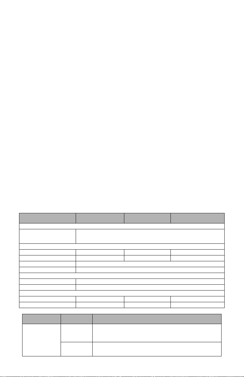
RatingsCompatibility
Model
POWER SUPPLY RATINGS
Input Voltage
CURRENT CONSUMPTION
Standby Current
Alarm (Transmitting) Current
Operating Frequency
Typical Antenna Gain
ENVIRONMENTAL SPECIFICATIONS
GS2060-RS
GPRS/GSM only
The panel Bell output shall be derated:
700mA - (Communicator mA) = (derated Bell output).
70mA @ 13.66V 80mA @ 13.66V 100mA @ 13.64V
4000mA @ 13.65V 4000mA @ 13.65V 400mA @ 13.64V
TL260-RS
Ethernet Only
13.6V DC:
Quad band 850MHz, 900MHz, 1800MHz, 1900MHz
Table 1: Communicator Ratings
TL260GS-RS
Ethernet &GPRS/GSM
2dBi
Operating Temperature 0°C - 49°C (32°F- 120°F)
Humidity 5% ~ 93% relative humidity, non-condensing
MECHANICAL SPECIFICATIONS
Board Dimensions (mm) 100 × 150 × 15 100 × 150 × 18 100 × 150 × 15
Weig h t (grams) wi t h bracket 310 290 320
Table 2: Compatible Receivers, and Power Panels
Communicator
GS2060-RS
TL260-RS
TL260GS-RS
Receiver/
Panel
Receiver
Power Panel
Description
• Sur-Gard System I Receiver, version 1.30+
• Sur-Gard System II Receiver, version 2.10+
• Sur-Gard SG-DRL3-IP, version 2.30+ (for Sur-Gard System III Receiver)
• Sur-Gard SG-DRL4-IP version 1.20+ (for Sur-Gard System IV Receiver)
• Power Series PC1616, version 4.5+
• Power Series PC1832, version 4.5+
• Power Series PC1864, version 4.5+
4

NOTE: Enter [*][8][Installer Code] [900] at keypad to view the Power Panel Version number.
Products or components of products, which perform communications functions only shall comply with the
requirements applicable to communications equipment as specified in UL60950 or CAN/CSA-C22.2 No. 950-1,
Information Technology Equipment - Safety - Part 1: General Requirements. Where network interfaces are
internal to the control unit or receiver , compliance to CAN/CSA-C22. 2 No. 950-1 is adequate. Such components
include, but are not limited to: hubs; routers; NIDs; Third party communications service providers; DSL
modems; and Cable modems.
Customer Furnished Equipment
The Communicator provides monitoring and control via an RS-232 link to an external device, Customer Furnished Equipment (CFE). The default communication link speed is 115.2 KB and this option is programmable
by the installer. All life-safety events are encrypted and transmitted by the GPRS path to the central monitoring
station . All life-style events are transmitted by the RS-232 link, using IT V2.0 protocol to the customer device.
NOTE: Customer furnished equipment may be an interface device which connects to security panels,
IP cameras, sensors, Z-wave based home automation devices, etc. to deliver a host of advanced functionality.
The following features are available with the RS-232 Communications Interface:
• Communicator faults can be transmitted.
• Panel communication errors are reported to the CFE.
• Real time reporting of zone status information to the CFE.
• Remote update the Communicator (flash upgrade).
• SMS incoming “wake up” for the GPRS channel.
• WEB login will request an incoming session with the Communicator.
• Zone Label Programming.
NOTE: Communicator buffers 1,000 date/time stamped Life Style events to CFE as First In First Out (FIFO).
PRE INSTALLATION CONFIGURATION
Encryption
The Communicator uses 128 Bit AES Encryption. Encryption can only be enabled from the monitoring station
receiver. Each receiver can independently have encryption enabled or disabled. When encryption is enabled,
the central station will configure the device to encrypt communications the next time the Communicator module
performs a communication to that receiver.
NOTE: Packets will start being encrypted only after the next event is sent to that receiver, or if the unit
is restarted.
Before leaving the installation site, the Communicator TL260-RS/TL260GS-RS shall be connected via
an APPROVED (acceptable to the local authorities) Network Interface Device (NID) (e.g., for UL Installations, U60950 listed NID). All wiring shall be performed according to the local electrical codes.
COMMUNICATOR PRE INSTALLATION CONFIGURATION
This GSM/Ethernet -RS Commu nicator is fixed a nd shall be installed by Service Person s only. (Service Person is
defined as a person having the appropriate technical training an d experience necessary to be aware of hazards to
which that person may be exposed in performing a task and can also take measures to minimize the risks to that person or other persons). The Communicator shall be installed and used within an environment that provides the pollution degree max 2, over voltages category II, in non-hazardous, indoor locations only. This manual shall be used with
the Installation Manual of the alarm control panel which is connected to the GSM/Ethernet Communicator. All instructions specified within the panel manual must be observed.
All the local rules imposed by local electrical codes shall be observed and respected during installation.
Running the Ethernet Cable
(TL260-RS/TL260GS-RS only)
A Category 5 (CAT 5) ethernet cable must be run from a source with Ethernet/Internet connectivity to the Com-
municator module, inside the Power Panel. The Communicator end of the cable must be terminated with an
RJ45 plug, which will connect to the Communicator’s RJ45 jack after the Communicator is installed. All requirements for installation of CAT5 ethernet cable must be observed for correct operation of the Communicator,
including, but not limited to, the following:
• Do NOT strip off cable sheathing more than required for proper termination.
• Do NOT kink/knot cable.
• Do NOT crush cable with cable ties.
• Do NOT untwist CAT5 pairs more than 1.2cm (½ in.).
• Do NOT splice cable.
• Do NOT bend cable at right angles or make any other sharp bends.
NOTE: CAT5 specification requires that any cable bend must have a minimum 5 cm (2 in.) bend radius.
Do NOT exceed maximum 15cm (6 in.) from center of ferrite to T-Link Network Connector. Maximum
length of CAT 5 cable is 100m (328 ft.).
Running the RS-232 Cable
An RS-232 cable must be connected to the CFE and cable run to the Communicator module inside the panel.
NOTE: Maximum cable length for RS-232 cable is 16 m (50 ft.)
At the communicator, attach wires as fol lows:
1. Securely fasten the TX wire on the terminal block.
2. Securely fasten the RX wire on the terminal block.
3. Securely fasten the GND wire on the termina l bl o ck.
5
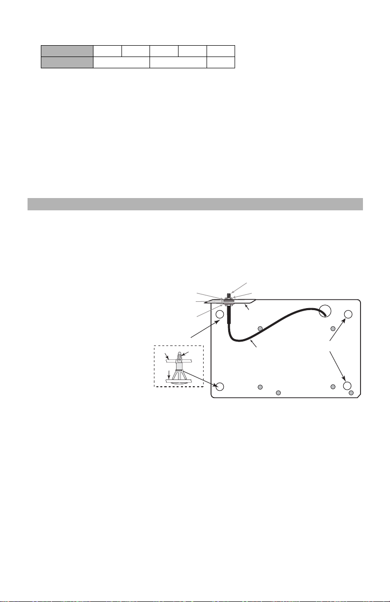
Table 3: RS-232 Connector Pin Assignment
DG009344
Brass Washer
Nylon washer (flat)
Nylon Washer
with bushing
(thicker flat washer)
Brass nut
Antenna
Mounting Tab
Mounting
Holes
Mounting Holes
Antenna
Cable
Mounting Plate
for UA585
External Antenna
Screw Thread
Communicator
Board
Mounting
Plate
Stand Off
Figure 1 Communicator Mounting Bracket
PIN 12345
Signal Name TX RX GND
4. Connect the other end of the RS-232 cable to the Customer Furnished Equipment.
Inserting and Removing the SIM Card
1. If the Communicator is installed in a Power Panel, r emove the fron t cove r of th e Pane l to a ccess SIM holde r.
2. Remove power from the panel and disconnect the battery.
3. On the SIM card holder push gently to slide the cover towards the Printed Circuit Board (PCB) antenna, as
indicated by the arrow on SIM holder, to OPEN. This will unlatch the SIM card holder on the side closest to
edge of the Communicator PCB.
4. Lift up the SIM card holder from the side that is not hinged.
NOTE: The SIM can be damaged by bending, or scratching contacts. Use caution when handling SIM
cards.
5. Insert or remove the SIM card, noting the orientation of the notches on the SIM card and the SIM card holder.
6. When inserting a SIM card, insert the card in the proper orientation and gently push the SIM card holder
down and slide the holder as indicated by the arrow on SIM holder, to LOCK. (See Figure 3).
7. Reconnect the backup battery, apply AC power to panel, and replace the pane l cover.
Hardware Reset
The Communicator can be hardware reset by installing a jumper between Pins 4 and 5 on the AUDIO/
DEFAULT connector and restarting the Communicator. Installing jumper during normal operation has no effect.
INSTALLING THE GSM/ETHERNET COMMUNICATOR IN PANEL
Installing Communicator with PC1616/1832/1864 Panel
WARNING!
EFORE INSTALLING THE COMMUNICATOR WITHIN THE PANEL, DISCONNECT POWER AND
B
TELEPHONE LINE FROM THE PANEL.
1. To assemble mounting bracket, perform the following (See Figure 1).
a. Remove the 4 white plastic
standoffs from the bag provided
with the Communicator kit.
b. Insert the 4 standoffs through
the back of the supplied mounting bracket, into the holes at
each corner. (The antenna
mounting tab should be facing
away from you).
c. Place the bracket on a flat,
solid surface. Hold the Communicator face up and orient the 4
holes on the Communicator
with the 4 standoffs protruding
from the bracket. Push the
Communicator firmly and
evenly onto the standoffs until it
is securely attached to the
mounting bracket.
d. Remove the alarm panel front
cover.
e. TL260-RS/TL260GS-RS only: Remove and discard the circular knockout located in the top-right section
of the panel. (This hole will be used for connection of the supplied radio antenna).
f. TL260-RS/TL260GS-RS only: Connect the supplied 12.7cm (5”) antenna cable to the radio, by passing
the connector through the hole on back of the mounting bracket to the Communicator board. Push the
antenna connector firmly into the socket on the GSM radio. (SeeFigure 3).
6

g. TL260-RS/TL260GS-RS onl y: Place the nylon
PC-Link
Cable Connector
(screw)
Quad band
Whip Antenna
PC1616/1832/1864
GSM Radio
RJ-45
UA585
Use light pressure
to attach antenna
Finger Tight only.
Figure 2 PC1616/1832/1864 Control Panel
washer with bushing (thick flat washer) onto the
threaded section of the antenna cable. Insert the
threaded section through the antenna mounting
knockout hole. Place the second nylon washer (flat),
followed by the brass washer and the brass nut, onto
the threaded section of the cable, outside the panel.
Tighten the assembly by hand only (Finger Tight - Do
not overtighten the assembly).
2. Install the Communicator module into the panel:
(See Figure 3).
a. Attach one end of the PC-LINK cable to the panel
PC-LINK header on the panel (red wire goes on Pin 1
of the panel PC-LINK header).
b. Insert the assembled Communicator into the panel.
NOTE: Ensure that the threaded antenna connection
point is visible through the knockout hole at the top
right of the panel.
c. Locate the screw hole on the right side wall of the
panel. See Figure 2 (screw). Line up the assembled
Communicator with the side wall of the panel and,
using the screw provided, secure the mounting
bracket to the panel.
d. Attach the other end of the PC-LINK cable to the
Communicator (black wire goes on Pin 1 of the Com-
municator). See Figure 3.
e. TL260-RS/TL260GS-RS o nly: Using light pressure
(finger tight), attach the supplied 5” white quad band whip antenna to the threaded antenna connection
point at top of the panel.
WARNING!
GS2060-RS/TL260-RS/TL260GS-RS MODULES ARE POWER LIMITED. D O NOT ROUTE ANY
WIRING
OVER THE CIRCUIT BOARD. M AINTAIN AT LEAST 25.4MM (1IN.) SEPARATION BETWEEN
BOARD AND WIRING. A MINIMUM OF 7MM (1/4 IN.) SEPARATION MUST BE MAINTAINED AT
CIRCUIT
POINTS BETWEEN NON-POWER LIMITED WIRING AND POWER LIMITED WIRING.
ALL
3.To electrically connect the Communicator to the panel, perform the following steps (See Figure 3
a. Disconnect both AC power and battery connections from the panel.
Module Power Connection
b. Attach a wire from the Communicator’s left PWR terminal to the panel’s BELL+ terminal.
NOTE: For ULC Commercial Fire Monitoring applications: Do NOT connect any devices on the
Bell + terminal other than the Communicator.
c. Attach a wire from the Communicator’s GND terminal (beside PWR) to the panel’s AUX -
d. Attach a wire from the Communicator’s SHLD terminal to the panel’s EGND terminal. (Protective earth
ground).
External Bell/Siren Connection (Optional)
e. Attach a wire from the Communicator’s right PWR terminal to the positive (+) terminal on the Bell/Siren.
(See Figure 3).
f. Attach the panel’s BELL
NOTE: If a Bell/Siren is not used, in stall the 1 K ½ W 5% resistor (Brown, Black, Red, Gold) (supplied
with the panel) between the panel’s Bell + and Bell
terminal on the Communicator.
g. Confirm that the SIM card is inserted and locked. (See
-
terminal to the negative (-) terminal on the Bell/Siren.
-
terminals, then only wire the BELL + to the PWR
Figure 3).
terminal.
7
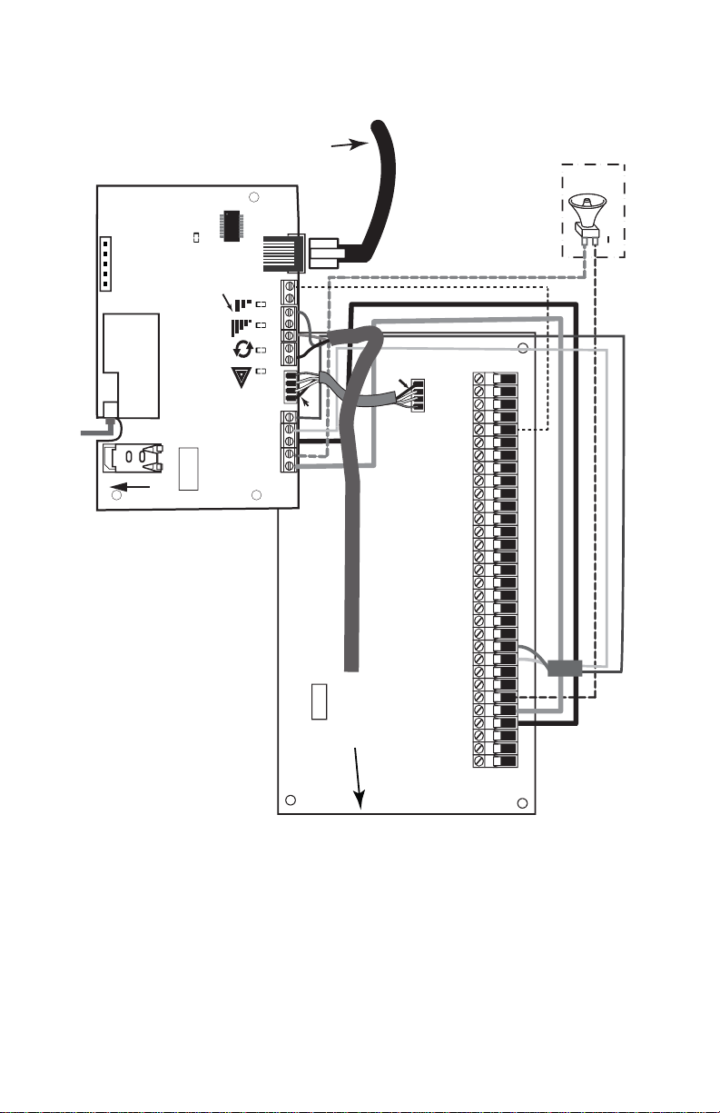
h. Insert the PC-LINK connector into the Communicator’s PC-LINK socket. (Black wire on Pin 1 on the
Figure 3 Communicator Wiring Diagram
3
T o external antenna
Communicator).
Supervised
Use only CAT5
From NID
(GS2060-RS/TL260GS-RS)
AUDIO/ DEFAUL T
Jumper pins 4 and 5
to reset.
1
YELLOW
(TL260-RS only)
Network Link
(GS2060-RS
TL260GS-RS only)
RJ-45
SHLD
GND
GND
RX+
TX+
GSM Radio
RX 1 & RX 2
TL260-RS
TL260GS-RS
SIM
DSC
c
k
L
o
REV0 1
UA585
Input Ratings from Bell +:
+11.1V ~ +12.6 VDC
100mA standby; 400mA alarm
PC-LINK
Black
GRN
GS2060-RS
YEL
COM
PWR
PWR
UA503
RS-232
To External Device
DSC Panel min power requirements:
- 16 VAC 40 VA transformer;
- 12 VDC 7Ah battery
PC1616/1832/1864
100 m (328 ft)
Maximum cable length
R-1
T-1
TIP
RING
EGND
Z1 COM Z2 Z3 COM Z4 Z5 COM Z6 Z7 COM Z8
PGM2 PGM4
PGM1 PGM3
GRN
YEL
BLK
RED
BELL BELL +
AUX -
AUX+
AC
AC
16 m (50 ft)
Black
PC-LINK
1
-
+
External Bell/Siren
Green
Yellow
Maximum cable length
DG 00959
RS-232 Connection for Customer Furnished Equipment
4. Run a 3 wire RS-232 cable from the CFE to the Panel and Communicator.
5. Terminate the wires on the Communicator, as follows:
a. Connect the TX wire to the TX terminal on the Communicator.
b. Connect the RX wire to the RX terminal on the Communicator.
c. Connect the ground wire to the GND terminal on the Communicator.
d. Connect the other end of the RS-232 cable as required by the CFE installation guide.
Install Network Cable (TL260-RS/TL260GS-RS only)
6. Route the CAT 5 Ethernet cable through back of the panel and plug it into the Communicator’s RJ45 jack.
Before leaving the premises the Ethernet communication lines must first be connected to an approved
(acceptable to local authorities) type NID, (UL installations, UL 60950 listed NID, for ULC installations
CAN/CSA C22.2. No. 60950-1 Certified NID). All wiring shall be performed according to the local electri-
cal codes.
8

7. Perform the following steps for initial power on of the panel with Communicator installed:
a. Reconnect the telephone line, AC power and battery + connector to the Panel. (the Communicator and
Panel will power up together).
b. Observe that the Communicator’s red and yellow LEDs are flashing together while it initializes. The red
and yellow LEDs will continue to flash until the Communicator has successfully communicated to all programmed receivers. If this is the first time the Communicator has been powered up, the module will
request programming remotely.
NOTE: Initialization may take several minutes to complete. Re d and y ell ow LEDs wi ll fl ash together dur ing initialization. Do not continue to next step until the red and yellow LEDs have stopped flashing. (If
only the yellow LED is flashing, there is a Communicator trouble and the Green LEDs are not valid for
Communicator Placement Test). Correct trouble indicated by flashes on yellow LED before continuing.
(See Table 6 for troubleshooting assistance).
c. At the keypad, enter [*][8][Installer Code][382] and confirm that Toggle Option [5] is ON
(GPRS/Ethernet Module Enabled).
8. TL260-RS/TL260GS-RS only: Perform the C omm u n i ca to r Pl ac ement Test on page 10.
9. Mount the Panel in final location.
INITIAL PANEL PROGRAMMING
Domain Name Service (DNS) programming is not permitted in UL/ULC listed systems.
Keypad Data Display
• Section-Toggle Options: The number is displayed when Toggle is ON, the number is not displayed when
Toggle is OFF. (e.g., Toggle Options displays: “[
Pressing keys 1 through 8 will alternately turn the Toggle ON and OFF.
• HEX/Decimal Data: Values that are provided with two defaults, separated by a / character, use the format:
hexadecimal followed by decimal equivalent (e.g., Default [0BF5/3061]). Hexadecimal numbers are shown,
with all leading zeroes, to the full field length defined for the number.
Entering HEX values at keypad
To enter HEX values at the keypad, you must press the * key before entering the HEX value. (e.g., to enter “C” at
the keypad, press [*] [3].
Entering ASCII Characters at keypad
1. Press [*] and use scroll buttons [<] [>] to display “ASCII Entry” on the LCD screen.
2. Press [*] to select ASCII entry mode.
3. Use the [<] [>] scroll keys to display the character you want and press [*] to save and exit ASCII.
4. Repeat the steps above to enter another ASCII character.
PC1616/1832/1864 Initial Programming
Perform the following steps to ensure that the Communicator and the panel work together as intended.
These Sections must be programmed at the panel keypad. Enter
any values that are modified from their default, in the appropriate Worksheets for the Panel or Communicator.
1. In Panel Section [167] program 060 (seconds).
2. A valid Account Number must be entered in Section [851][021]. See Programming Section for details.
3. In Panel Sections [301], [302], and [303], program the central station telephone number that will be used for
the GPRS/Ethernet Communicator. Valid entries are:
a. A valid telephone number; signals will be routed to the central station using the Public Switched Tele-
phone Network (PSTN).
b. DCAA (Receiver 0); signals will be routed to GPRS/Ethern et Receivers 1 - 4 depending on programming
in Communicator Section [851] [006].
c. Panel Section [301] sets the Primary communication path, and may be configured as either PSTN or
Communicator routing. Panel Section [302] is redundant, and Panel Section [303] is the backup telephone number for Panel Section [301].
NOTE: The leading digit ‘D’ (dial tone detection) in the telephone number is pre-programmed.
4. In Panel Section [350], program the communication format as CID (03) or SIA FSK (04).
NOTE: If any of the panel telephone numbers have been set to DCAA, this section must be set to [04 ].
5. In Panel Sections [351] - [376], program the Communicator call direction options. Refer to the Panel Inst all a-
tion Manual for options.
6. In Panel Section [382], ensure Toggle Option [5] ‘GPRS/Ethernet Module Enabled’ is ON. If this option is
OFF, the yellow status LED on the Communicator will indicate ‘Panel Supervision Trouble’ (2 flashes) and
the unit can not be programmed via PC-LINK cable.
7. In Panel Section [401] set Toggle Option [2] ‘User Enable DLS’ to ON in order to perform p anel DLS sessi on
through GPRS or Ethernet.
NOTE: Before leaving the premises, the installer should verify all programmed communications paths.
Refer to Programming Worksheets Section [901] to send immediate test transmissions.
Communicator Troubles displayed on a PC1616/1832/1864
The General System trouble is the only trouble that will appear on the keypad Liquid Crystal Display (LCD)
when encountered by a Communicator installed in a PC1616/1832/1864. For more information about the trouble on the Communicator module refer to the panel event buffer. Log entry will show Fault or Restore for each
of the following events:
• T-LINK Networ k Fault/Restore: This log will occur for the following trouble conditions: SIM Lock Trouble,
GSM Trouble, Ethernet Trouble, or Connect 24 Configuration Trouble.
• T-LINK Recei ver Trouble/Restore: This log will occur for the following trouble conditions: Receiver Not
Available Trouble, Receiver Supervision Trouble, or Failure to Communicate (FTC) Trouble.
• T-LINK Comm. Fault/Restore: This log will occur when the panel loses communications with the Communi-
cator and will clear when communications is restored.
--3--6--
]”. Options 3 and 6 are ON, all others are OFF).
[*][8][Installer Code][Section Number]
. Record
9
 Loading...