

Tyco Safety Canada 09WT5500 User Manual
WT5500
1
23
4
5
6
7
8
0
#
9
*
Enter Code to
Arm System
<>
29007335R001
Installation Instructions
English
WARN ING :
NOTE:
Please refer to the System Installation Manual for information on limitations regarding pro duct use and function, and information on the limitations as to liability of the manufacturer.
These instructions are to be used in conjunction with the appropriate Control Panel Installation Manual, with which this equipment is intended to be us ed.
English
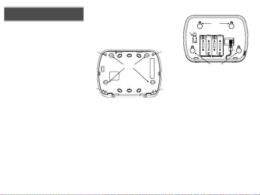
Screw
Holes
Screw
Holes
Mounting
Tabs
Screw
Holes
Screw
Holes
9049
$$
$$
$$
$$
9048
Mounting
Holes
Mounting
Holes
Batteries
Plug
Wire
Channel
Tamper
Switch
Installation Instructions
The WT5500 keypad can be used on security systems with up to 64
zones. The WT5500 keypad is compatible with the SI9155 system.
Specifications
• Temperature range: -6°C to +54°C (22°F to 140°F), Temperature
range for UL/ULC: 0°C to +49°C (32°F to 120°F)
• Humidity (MAX): 93%R.H.
• Plastic enclosure protection degree: IP30, IK04
• Transformer voltage: 4.5V @ 0.5A
•Battery: 3V
• WT5500 Current draw: 50mA (standby)/125mA (maximum)
•Wall mount tamper
• 5 programmable fun ction keys
• Ready (Green LED), Armed (Red LED), Trouble (Yellow LED), AC (Green
LED)
• Frequency: 433.92MHz (WT5500-433 only)
• Frequency: 868.35MHz (WT5500-868 only)
Unpacking
The WT5500 keypad package is available in five distinct configurations,
Standard, Proximity, Complete, Desk Stand, and Proximity Tags Only. The
contents of each are described below.
WT5500 - STANDARD WT5500P - PROXIMITY
•1 WT5500 keypad •1 WT5500P keypad
•1 WT5500BRK wall bracket •1 WT5500BRK wall bracket
•1 Installation manual •1 Installation manual
•1 Inner door sticker •1 Inner door sticker
•4 AA batteries •4 AA batteries
•1 Hardware pack •1 Hardware pack
WT5500D - COMPLETE WT5500DMK - DESK STAND
•1 WT5500 keypad •1 WT5500DMK keypad
•1 WT5500X AC transformer •1 WT5500X AC transformer
•1 WT5500DMK desk stand •1 Installation manual
•1 WT5500BRK wall bracket •1 Hardware pack
•1 Installation manual
•1 Inner door sticker
•4 AA batteries
•1 Hardware pack
•1 PT4 (433MHz proximity tag) or
PT8 (868MHz proximity tag)
PROXIMITY TAGS ONLY
•1 PT4 (433MHz proximity tag) or
PT8 (868MHz proximity tag)
Mounting
You should mount the keypad where it is accessible from designated points
of entry and exit. Once you have selected a dry and secure location, perform
the following steps to mount the keypad.
Mounting Plate
1. Locate the screw holes (4) at each corner of the mounting plate.
2. With the smooth face of the mounting plate facing up, use the four screws
provided to affix the mounting plate to the wall.
3. Align the four mounting slots in the WT5500 housing with the four
mounting tabs protruding from the mounting plate.
4. Slide the unit into place.
5. Firmly but carefully snap the unit down onto the mounting plate.
Desk Stand
1. Place the desk stand on a secure, uncluttered surface.
2. Align the four mounting slots in the WT5500 housing with the four
mounting tabs protruding from the desk stand.
3. Slide the unit into place.
4. Firmly but carefully snap the unit down onto the desk stand.
•1 Installation manual
Apply Battery Power
1. Slide the unit up and out from the mounting plate. The bay for the four AA
batteries is open and clearly visible at the back of the unit.
2. Insert the batteries as directed on the unit.
3. Replace the unit on the mounting plate.
Apply AC Power
1. Slide the unit up and out from the mounting plate.
2. Locate the AC adaptor jack at the back of the unit housing.
3. Place the AC adaptor plug in the housing indentation, perpendicular to the
unit. Insert the adaptor plug firmly into the jack.
4. Pivot the adaptor plug downwards so that it fits flush with the housing.
Guide the AC wire along the channel provided in the unit housing; the wire
should finally extend through the bottom of the housing.
5. Replace the unit on the mounting plate.
6. Plug the AC adaptor into a wall outlet.
Programming the Keypad
There are several programming options available for the keypad. These are
described below. Programming the keypad is similar to programming the
rest of the system. To turn an option on or off, press the number corresponding to the option on the number pad. The numbers of the options that are
currently turned on will be displayed along the top of the LCD. For information on programming the rest of your security system, please refer to your
system’s Installation Manual.
Broadcasting LCD Labels
All LCD programming is done using the keypad. If more than one LCD keypad is present on the system, labels programmed at one keypad can be
broadcast to all other LCD keypads. Perform the following procedure in order
to broadcast labels:
1. Program one LCD keypad completely.
2. Enter keypad programming by pressing 4 > 8 >
3. Enter Section 998 at the keypad that was programmed. The keypad will now broadcast the label programming to
the PC9155. The PC9155 will then program the labels in others WT5500 keypads that have been enrolled by way
of the RF link.
NOTE: This operation may take several minutes.
4. When the keypad is finished press the # key to exit.
NOTE: Label broadcast from this keypad is only compatible with other WT5500 keypads.
Language Programming
Hold the (<>) keys for 2 seconds to enter language programming. Scroll to the desired language and press 4 to
select.
NOTE: If Section 077, Option 4 is turned off, language programming can only be performed while
in installers programming.
Enrolling the Keypad
The WT5500 must be configured in tandem with the PC9155 in order for the system to function as desired.
1. Turn on the PC9155 unit. The panel will be alert to any keypad enrollment activity for a period of two minutes. Note
that the unit’s Ready and AC LEDs will be activated for this two-minute p eriod.
2. A WT5500 must be turned on during this two-minute period for it to be assigned to the PC9155.
3. Simultaneously press and hold the * and # keys; by doing so you force the keypad to broad cast its ESN (electronic
security number). The keypad will intermittently flash its Ready and AC LEDs (one second on, one second off). This
indicates that the keypad is in enrollment mode.
4. When the keypad has been successfully enrolled - this should take less than 30 seconds - on the system, the message ‘Enrollment Successful’ will be displayed on the keypad LCD for five seconds. The Ready and AC LEDs will
return to their ready state.
Any additional keypads to be added to this system can be enrolled in the same manner as described above. The system will add each keypad to the next available slot, and this slot number will be displayed on the keypad’s LCD display once the keypad has been successfully enrolled.
Programming Labels
1. Use this section to assign a meaningful name (e.g. Front Door, Hallway, etc) to each zone.
2. Enter keypad programming by pressing 4 > 8 >
label to be programmed.
3. Use the arrow keys (<>) to move the cursor underneath the letter to be changed.
4. Press the number keys 1 through 9, corresponding to the letter you require. For example, pressing number key 2
once will display the letter D; pressing it again will display the letter E; pressing it a third time will display the letter
F, a nd s o on .
[1] - A, B, C, 1 [4] - J, K, L, 4 [7] - S, T, U, 7 [0] - Space
[2] - D, E, F, 2 [5] - M, N, O, 5 [8] - V, W, X, 8
[3] - G, H, I, 3 [6] - P, Q, R, 6 [9] - Y, Z, 9,0
5. When the required letter or number is displayed use the arrow keys (<>) to scroll to the next letter.
6. When you are finished programming the Zone Label, press Q. Scr oll to ‘Save’ and press Q again.
7. Repeat Steps 2 through 5 until all L abels are programmed.
Installer Code
> 4.
Installer Code
> 4. Enter the 3-digit section number for the
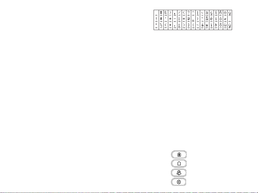
ASCII Characters
Changing Brightness/Contrast
LCD Keypads
1. Press [4][6][Master code].
2. Use the arrow keys (<>) to scroll to either Brightness Control or to Contrast Control.
3. Press 4 to select the setting you want to adjust.
4. a) Brightness Control: There are multiple backlight levels. Use the arrow keys (<>) to scroll to the desired level.
5. b) Contrast Control: There are 10 different display contrast levels. Use the arrow keys (<>) to scroll to the desired
contrast level.
6. To exit, press #.
Changing the Buzzer Level
LCD Keypads
1. Press [4][6][Master Code].
2. Use the arrow keys (<>)to scroll to Buzzer Control.
3. Use the arrow keys (<>) to scroll to the desired buzzer level among the 21 available selections.
4. To exit, press #.
Keypad Enrollment
Enter keypad programming by pressing 4 > 8 >
[0] Partition / Slot Assignment
Digit Option
1st Partition Assignment (0=Global Keypad) 0 to 8 1 I_____I
2nd Slot Assignment 1 to 8 LED,ICON=1/LCD=8 I_____I
[1]-[5] Function Key Assignment
Function Key Button
[1] Function Key 1 Assignment 00 to 32 03 Stay Arm I_____I_____I
[2] Function Key 2 Assignment 00 to 32 04 Away Arm I_____I_____I
[3] Function Key 3 Assignment 00 to 32 06 Chime On/Off I_____I_____I
[4] Function Key 4 Assignment 00 to 32 14 Bypass I_____I_____I
Installer’s Code
Range
Val id
Range
Val id
Defa
> 000.
ult
Default
Function
 Loading...