

Tyco Safety Canada 09RFK55M User Manual
RFK5501/5500-433 v1.1
123
456
78
0
*
#
9
29007608R001
Installation Instructions, Instrucciones de instalación
English, Español
WARN ING: Please refer to the System Installation Manual for information on limitations regarding product use and function and information on the limitations as to liability of the manufacturer.
NOTE: These instructions shall be used in conjunction with the system Installation Manual of the Control Panel with which this equipment is intended to be used.
ATENCIÓN: Consulte el Manual de instalación del sistema para obener información sobre las limitaciones del uso y funciones del producto, así como las limitaciones de la responsabilidad del fabricante.
NOTA: Estas instrucciones deberán utilizarse conjuntamente con el Manual de instalación del sistema del Panel de control con el que se vaya a utilizar este equipo.
English
Installation Instructions
The RFK5501/5500 keypads can be used on security systems with up
to 64 zones. These keypads are compatible with the latest version of
the folllowing DSC security systems:
•PC580 •PC585 •PC1555MX •PC1565
•PC1616 •PC1832 •PC1864 •PC5005
•PC5008 •PC5010 •PC5015 •PC5016
•PC5020
The RFK5501/5500 keypads combine a wireless receiver with the
respective keypad.
Specifications
• Temperature range: -10°C to +55°C (14°F to 131°F), Temperature
range for UL/ULC: 0°C to +49°C (32°F to 120°F)
• Humidity (MAX): 93%R.H.
• Plastic enclosure protection degree: IP30, IK04
• Voltage rating: 12V
• Connects to control panel via 4-wire Keybus
• 1 keypad zone input/PGM output*
• Current draw: 75mA (standby)/135mA (maximum)
• Wall mount tamper
• 5 programmable function keys
• Ready (Green LED), Armed (Red LED), Trouble (Yellow LED), AC
(Green LED)
• Low temperature sensor
• Frequency: 433.92MHz
• Up to 32 wireless zones
NOTE: * Zone not to be programmed as Fire type or 24h type.
Unpacking
The Power keypad package includes the following parts:
•One Power keypad •Keypad inner door labels
•Four mounting screws •1 tamper switch
•2 end-of-line resistors •Installation Instructions
Placement
The RFK5501/5500 performs best in locations where RF interference
is minimal. To find an optimal mounting location for the keypad, perform the following placement test:
Step 1- Temporarily connect the Keybus wires to the keypad (refer to
wiring instructions).
Step 2- Hold the keypad in the intended mounting location.
DC nominal
Step 3- Enter keypad programming mode by pressing [
code], then enter section[904].
Step 4- If the yellow Trouble LED is on, interference leve ls are high and
a new mounting location should be found. If the LED is flashing or off,
interference is low and the location is good.
Mounting
You should mount the keypad where it is accessible to designated
points of entry and exit. Once you have selected a dry and secure location, perform the following steps to mount the keypad.
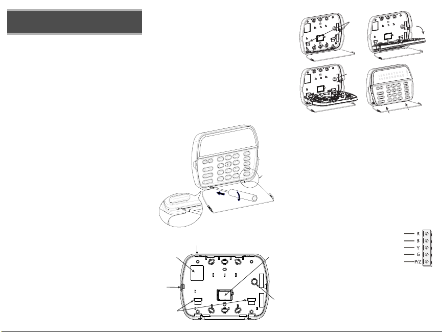
Disassemble Keypad
1. Insert a flat head screwdriver into the provided slot (first of two)
2. Move screwdriver toward the back plastic and lift as in the below diagram. This will unhook one side of the front plastic.
3. Repeat step # 1 and 2 on the second provided slot to disconnect the front plastic and allow access for wiring.
1
4][8][installer
3
2
Mount and Wire Keypad
Knock Out
Wiring Slot
Knock Out
Hooks
Knock Out
Tamper
1.
3.
1. Secure Keypad to wall using mounting holes. Use all 4 screws provided unless mounting on a single gang box.
2. Place keypad into hooks on the backplate and swing down to engage.
3. Run wire through wiring slot or knockouts. Connect Keybus and PGM/Zone wiring to keypad. Place tamper switch into tamper hole on backplate.
4. Remove keypad from hooks. Place keypad into backplate, ensure the wire
is pushed back into the wall as much as possible. Route the wire inside
the keypad ensuring high components are avoided. Snap the front assembly closed, ensuring that there is no pressure to the keypad from the wire
below.
NOTE: If any tension found between the front keypad assembly and wiring,
please open the keypad reroute the wire and close again. Repeat these
steps until the keypad is closed properly.
Wiring
1. Before wiring the unit, ensure that all power (AC transformer and battery) is disconnected from the control panel.
2. Connect the four Keybus wires from the control panel (red, black, yellow and green) to
the keypad terminals. Refer to diagram:
3. If programmed as an input, you can connect a device - such as a door contact - to
the ‘P/Z’ terminal of the keypad. This eliminates the need to run wires back to the
control panel for the device. To connect the
zone, run one wire from the device to the ‘P/Z’ terminal and the other wire
from the device to the B (black) terminal. For powered devices, run the red
wire to the R (positive) terminal and the black wire to the B (negative)
terminal. When using end of line supervision, connect the zone according
to one of the configurations outlined in your system’s Installation Manual.
4. If the ‘P/Z’ terminal is programmed as an output, the output follows the
PGM programmed in Section [080]. A small relay, buzzer or other DC
Hooks
Tam p e r
2.
4.
Press to Snap
RFK5501/5500
RED
BLK
YEL
GRN
To zone or
PGM output
Swing
to engage
operated device may be connected between the positive supply voltage
41
Toggle Option
1 _ _ 4 _ _ _ _
and the ‘P/Z’ terminal (maximum load is 50mA).
NOTE: For UL Residential Fire Installations use at least one additional DSC
compatible keypad in conjunction with an RFK5501/5500-433 keypad or
install the RFK5501/5500-433 keypads within 3 feet from the control unit
and mechanically protect the keybus wires
Applying Power
Once all wiring is complete, and the equipment is secured to the building
structure with at least two screws apply power to the control panel:
1. Connect the battery leads to the battery.
2. Connect the AC transformer. For more information on control panel power specifications, see the control panel Installation Manual.
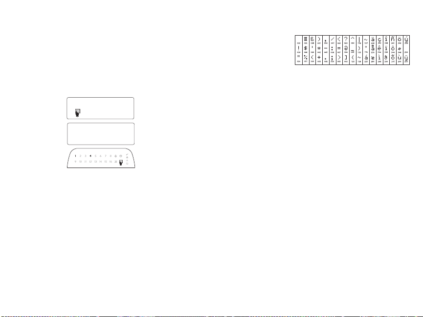
Programming the Keypad
There are several programming
options available for the keypad.
These are described below. Programming the keypad is similar
to programming the rest of the
system. When you are in the keypad programming sections, the
keypad will display which
options are turned on along the
top of the display. To turn an
option on or off, press the number corresponding to the option
on the number pad. The numbers of the options that are currently turned
ON will be displayed. For example, if options 1 and 4 are on, the display
will look like diagram shown on the different keypad displays.
For information on programming the rest of your security system, please
refer to your system’s Installation Manual.
Broadcasting LCD Labels
All LCD programming is done per keypad. If more than one LCD keypad is
present on the system, labels programmed at one keypad can be broadcast
to all other LCD keypads. Perform the following procedure in order to broadcast labels:
Step 1 - Program one LCD keypad completely.
Step 2 - Make sure all LCD keypads are connected to the Keybus.
Step 3 - Enter keypad programming by pressing [4][8][Installer
Code][4], then enter section [998] at the keypad that was programmed.
The keypad will now broadcast all the information programmed to all the
other LCD keypads on the system.
Step 4 - When the keypad is finished press the [#] key to exit.
NOTE: LCD Label broadcast from this keypad is only compatible
with other RFK5501/5500 Keypads.
Language Programming
Hold (<>) keys for 2 seconds to enter language programming, scroll to
the desired language and Press [4] to select.
NOTE: If section [077] option 4 is OFF, language programming
can only be performed while in installers programming.
Enrolling the Keypad
The keypad will need to be assigned to a partition and slot if supervision or
keypad zones are being used. Keypad assignments and keypad option programming must be done at each keypad individually.
The 1st digit of keypad assignment is used to determine partition assignment (1 to 8). If partitioning is not used, enter [1]. For Global Keypads,
enter [0].
NOTE: LED and ICON keypads cannot be programmed as Global Keypads
The 2nd digit of keypad assignment is used to determine slot assignment
for keypad supervision. Each keypad will be assigned a different slot number from 1 to 8. RFK5501/5500 LCD keypads come defaulted in slot 8. If
LCD keypads are used one LCD keypad must remain in slot 8.
NOTE: The keypad enrolls as two modules:
Light 1 = keypad section
Light 17 = receiver section
NOTE: Deleting all wireless devices from the keypad or defaulting the keypad will cause a supervisory fault.
Enter the following at each keypad installed on the system:
1. Enter Installer Programming by pressing [4][8][Installer’s Code]
2. Press [000] for Keypad Programming
3. Press [0] for Partition and Slot Assignment
4. Enter the 1st digit (0 to 8 for partition assignment)
5. Enter the 2nd digit (1 to 8 for slot assignment supervision)
6. Press the [#] key twice to exit programming.
7. After assigning all keypads, perform a supervisory reset by entering
[4][8][Installer’s Code][902] and wait for 60 seconds.
8. Press the [#] key to exit programming after 60 seconds.
Programming Labels
1. Enter keypad programming by pressing [4][8][Installer Code][4]. Enter
the 3-digit section number for the label to be programmed.
2. Use the arrow keys (<>) to move the underline bar underneath the letter to be changed.
3. Press the number keys [1] to [9] corresponding to the letter you require.
The first time you press the number the first letter will appear. Pressing the
number key again will display the next letter
[1] - A, B, C, 1 [4] - J, K, L, 4 [7] - S, T, U, 7 [0] - Space
[2] - D, E, F, 2 [5] - M, N, O, 5 [8] - V, W, X, 8
[3] - G, H, I, 3 [6] - P, Q, R, 6 [9] - Y, Z, 9,0
4. When the required letter or number is displayed use the arrow keys (<>) to scroll to the next letter.
.
5. When you are finished programming the Zone Label, press the [4] key,
scroll to “Save,” then press [4].
6. Continue from Step 2 until all Labels are programmed.
ASCII Characters
Changing Brightness/Contrast
LCD Keypads
1. Press [4][6][Master code].
2. Use the [<][>] keys to scroll to either Brightness Control or Contrast Control.
3. Press [4] to select the setting you want to adjust.
4. a) ‘Brightness Control’: There are multiple backlighting levels. Use the [<][>]
keys to scroll to the desired level.
b) ‘Contrast Control’: There are 10 different display contrast levels. Use the
[<][>] keys to scroll to the desired contrast level.
5. To exit, press [#].
LED/ICON Keypads
1. Press [4][6][Master Code].
2. Use the [>] key to move through the 4 different backlighting levels.
3. The level is automatically saved when you press [#] to exit.
Changing the Buzzer Level
LCD Keypads
1. Press [4][6][Master Code].
2. Use the [<][>] keys to scroll to Buzzer Control.
3. There are 21 different levels, use the [<][>] keys to scroll to the desired level.
4. To exit, press [#].
LED/ICON Keypads
1. Press [4][6][Master Code].
2. Use the [<] key to move through the 21 different buzzer levels.
3. The level is automatically saved when you press [#] to exit.
Broadcasting Door Chime
All door chime programming is done per keypad. If more than one keypad is
present on the system, door chime programmed at one keypad can be broadcast to all other keypads. Perform the following procedure in order to broadcast
door chime:
Step 1 - Program one keypad completely.
Step 2 - Make sure all keypads are connected to the Keybus.
Step 3 - Enter keypad programming by pressing [4][8][Installer Code][4], then
enter section [994] at the keypad that was programmed. The keypad will
now broadcast all the door chime information programmed to all the
other keypads on the system.
Step 4 - When the keypad is finished press the [#] key to exit.

Limited Warranty
Digital Security Controls warrants that for a period of 12 months from the date of purchase, the
product shall be free of defects in materials and workmanship under normal use and that in fulfilment of any breach of such warranty, Digital Security Controls shall, at its option, repair or replace
the defective equipment upon return of the equipment to its repair depot. This warranty applies
only to defects in parts and workmanship and not to damage incurred in shipping or handling, or
damage due to causes beyond the control of Digital Security Controls such as lightning, excessive
voltage, mechanical shock, water damage, or damage arising out of abuse, alteration or improper
application of the equi pment.
The foregoing warranty shall apply only to the original buyer, and is and shall be in lieu of any and
all other warranties, whether expressed or implied and of all other obligations or liabilities on the
part of Digital Security Controls. Digital Security Controls neither assumes responsibility for, nor
authorizes any other person purpor ting to act on its behalf to modify or to change this warrant y, nor
to assume for it any other warranty or liability concerning this product.
In no event shall Digital Security Controls be liable for any direct, indirect or consequential damages, loss of anticipated profits, loss of time or any other losses incurred by the buyer in connection with the purchase, installat ion or operation or failure of this product.
Warning: Digital Security Controls recommends that the entire system be completely tested on a
regular basis. However, despite frequent testing, and due to, but not limited to, criminal tampering
or electrical disruption, it is possible for this product to fail to perform as expected.
Important Information:Changes or modifications not expressly a pproved by Digital Security Controls could void the user’s authority to operate this equipment.
FCC Compliance Statement
Caution: Changes or modifications not expressly approved by Digital Security Controls could vo id
your authority to use this equipment.
This equipment generates and uses radio frequency energy and if not in stalled and used properly, in
strict accordance with the manufacturer’s instructions, may cause i nterference to radio and television
reception. It has been type tested and found to comply with the limits for Class B device in accordance with the specifications in Subpart “B” of Part 15 of FCC Rules, which are designed to provide
reasonable protection against such interference in any residential installation. However, there is no
guarantee that interference will not occur in a particular installation . If this equipment does cause
interference to television or radio reception, which can be determined by turning the equipment off
and on, the user is encouraged to try to correct the interference by one or more of the following measures:
• Re-orient the receiving antenna
• Relocate the alarm control with respect to the receiver
• Move the alarm control away from the receiver
• Connect the alarm control into a different outlet so that alarm control and receiver are on different
circuits.
If necessary, the user should consult the dealer or an experienced radio/television technician for additional suggestions. The user may find the fol lowing booklet prepared by the FCC helpful: “How to
Identify and Resolve Radio/Television Interference Problems”. This booklet is available from the U.S.
Government Printing Office, Washington, D.C. 20402, Stock # 004-000-00345-4.
IMPORTANT - READ CAREFULLY: DSC Software purchased with or without Products and Components
is copyrighted and is purchased under the following license terms:
• This End-User License Agreement (“EULA”) is a legal agreement between
individual or entity who acquired the Software and any related Hardware) and
Controls, a division of Tyco Safety Products Canada Ltd.
integrated security systems and the developer of the software and any related products or
components (“HARDWARE”) which You acquired.
• If the DSC software product (“SOFTWARE PRODUCT” or “SOFTWARE”) is intended to be
accompanied by HARDWARE, and is NOT accompanied by new HARDWARE, You may not
use, copy or install the SOFTWARE PRODUCT. The SOFTWARE PRODUCT includes computer
software, and may include associated media, printed materials, and “online” or electronic
documentation.
You
(the company,
Digital Secur ity
(“DSC”), the manufacturer of the
©2009 Digital Security Controls, Toronto, Canada • www.dsc.com
• Any software provided along with the SOFTWARE PRODUCT that is associated with a separate
end-user license agreement is licensed to You under the terms of that license agreement.
• By installing, copying, downloading, storing, accessing or otherwise using the SOFTWARE
PRODUCT, You agree unconditionally to be bound by the terms of this EULA, even if this EULA
is deemed to be a modification of any previous arrangement or contract. If You do not agree to
the terms of this EULA, DSC is unwilling to license the SOFTWARE PRODUCT to You, and You
have no right to use it.
SOFTWARE PRODUCT LICENSE
The SOFTWARE PRODUCT is protected by copyright laws and international copyright treaties, as
well as other intellectual property laws and treatie s. The SOFTWARE PRODUCT is licensed, not
sold.
1.GRANT OF LICENSE This EULA grants You the following rights:
(a)
Software Installation and Use
of the SOFTWARE PRODUCT installed.
Storage/Network Us e
(b)
displayed, run, shared or used concurrently on or from different computers, including a
workstation, terminal or othe r digital electronic device (“Dev ice”). In other words, if You
have several workstations, You will have to acquire a license for each workstation where the
SOFTWARE will be used.
Backup Copy
(c)
only have one copy per license installed at any given time. You may use the back-up copy
solely for archival purposes. Except as expressly provided in this EULA, You may not
otherwise make copies of the SO FTWARE PRODUCT, including the printed materials
accompanying the SOFTWARE.
2. DESCRIPTIO N OF OTHER RIGHTS AND LIMITATIONS
(a)
Limitations on Reverse Engineering, Decompilation and Disassembly
engineer, decompile, or disassemble the SOFTWARE PRODUCT, except and only to the
extent that such activity is expressly permitted by applicable law notwithstanding this
limitation. You may not make any changes or modifications to the Software, without the
written permission of an officer of DSC. You may not remove any proprietary notices, marks
or labels from the Software Product. You shall institute reasonable measures to ensure
compliance with the terms and conditions of this EULA.
Separation of Component s
(b)
component parts may not be separated for use on more than one HARDWARE unit.
Single INTEGRATED PRODUCT
(c)
SOFTWARE PRODUCT is licensed with t he HARDWARE as a single integrated product. In
this case, the SOFTWARE PRODUCT may onl y be used with the HARDWARE as set forth in
this EULA.
Rental
- You may not rent, lease or lend the SOFTWARE PRODUCT. You may not make it
(d)
available to others or post it on a server or web site.
Software Product Transfer
(e)
of a permanent sale or transfer of the HARDWARE, provided You retain no copies, You
transfer all of the SOFTWARE PRODUCT (including all component parts, the media and
printed materials, any upgrades and this EULA), and provided the recipient agrees to the
terms of this EULA. If the SOFTWARE PRODUCT is an upgrade, any transfer must also
include all prior versions of the SOFTWARE PRODUCT.
(f)
Termination
if You fail to comply with the terms and conditions of this EULA. In such event , You
must destroy all copies of the SOFTWARE PRODUCT and all of its component
parts.
(g)
Trademarks
trademarks or service marks of DSC or its suppliers.
3. COPYRIGHT
PRODUCT (including but not limited to any images, photographs, and text incorporated
into the SOFTWARE PRODUCT), the accompanying printed materials, and any copies of
the SOFTWARE PRODUCT, are owned by DSC or its suppliers. You may not copy the
- For each license You acquire, You may have only one copy
- The SOFTWARE PRODUCT may not be installed, accessed,
- You may make back-up copies of the SOFTWARE PRODUCT, but You may
- You may not reverse
- The SOFTWARE PRODUCT is licensed as a single product. Its
- If You acquired this SOFTWARE with HARDWARE, then the
- You may transfer all of Your rights under this EULA only as part
- Without prejudice to any other rights, DSC may terminate this EULA
- This EULA does not grant You any rights in connection with any
- All title and intellectual property rights in and to the SOFTWARE
printed materials accompanying the SOFTWARE PRODUCT. All title and intellectual
property rights in and to the content which may be accessed through use of the
SOFTWARE PRODUCT are the property of the respective content owner and may be
protected by applicable copyright or other intellectual property laws and treaties. This
EULA grants You no rights to use such content. All rights not expressly granted under
this EULA are reserved by DSC and its suppliers.
4. EXPORT RESTRICTIONS
SOFTWARE PRODUCT to any country, person, or entity subject to Canadian export
restri ctions.
5. CHOICE OF LAW -
the Province of Ontario, Canada.
6. ARBITRATION -
determined by final and binding arbitration in accordance with the Arbitration Act, and
the parties agree to be bound by the arbitrator’s decision. The place of arbitration shall
be Toronto, Canada, and the language of the arbitration shall be English.
7. LIMITED WARRANTY
(a) NO WARRANTY
DOES NOT WARRANT THAT THE SOFTWARE WILL MEET YOUR REQUIREMENTS OR
THAT OPERATION OF THE SOFTWARE WILL BE UNINTERRUPTED OR ERROR-FRE E.
(b) CHANGES IN OPERATING ENVIRONMENT -
problems caused by changes in the operating characteristics of the HARDWARE,
or for problems in the interaction of the SOFTWARE PRODUCT with non-DSCSOFTWARE or HARDWARE PRODUCTS.
(c) LIMITATION OF LIABILITY; WARRANTY REFLECTS ALLOCATION OF RISK
EVENT, IF ANY STATUTE IMPLIES WARRANTIES OR CONDITIONS NOT STATED IN
THIS LICENSE AGREEMENT, DSC’S ENTIRE LIABILITY UNDER ANY PROVISION
OF THIS LICENSE AGREEMENT SHALL BE LIMITED TO THE GREATER OF THE
AMOUNT ACTUALLY PAID BY YOU TO LICENSE THE SOFTWARE PRODUCT AND
FIVE CANADIAN DOLLARS (CAD$5.00). BECAUSE SOME JURISDICTIONS DO
NOT ALLOW THE EXCLUSION OR LIMITATION OF LIABILITY FOR
CONSEQUENTIAL OR INCIDENTAL DAMAGES, THE ABOVE LIMITATION MAY NOT
APPLY TO YOU.
(d) DISCLAIMER OF WARRANTIES
WARRANTY AND SHALL BE IN LIEU OF ANY AND ALL OTHER WARRANTIES,
WHETHER EXPRESSED OR IMPLIED (INCLUDING ALL IMPLIED WARRANTIES OF
MERCHANTABILITY OR FITNESS FOR A PARTICULAR PURPOSE) AND OF ALL
OTHER OBLIGATIONS OR LIABILITIES ON THE PART OF DSC. DSC MAKES NO
OTHER WARRANTIES. DSC NEITHER ASSUMES NOR AUTHORIZES ANY OTHER
PERSON PURPORTING TO ACT ON ITS BEHALF TO MODIFY OR TO CHANGE THIS
WARRANTY, NOR TO ASSUME FOR IT ANY OTHER WARRANTY OR LIABILITY
CONCERNING THIS SOFTWARE PRODUCT.
(e) EXCLUSIVE REMEDY AND LIMITATION OF WARRANTY -
SHALL DSC BE LIABLE FOR ANY SPECIAL, INCIDENTAL, CONSEQUENTIAL OR INDIRE CT
DAMAGES BASED UPON BREACH OF WARRANTY, BREACH OF CONTRACT, NEGLI GENCE,
STRICT LIABILITY, OR ANY OTHER LEGAL THEORY. SUCH DAMAGES INCLUDE, BUT ARE
NOT LIMITED TO, LOSS OF PROFITS, LOSS OF THE SOFTWARE PRODUCT OR ANY
ASSOCIATED EQUIPMENT, COST OF CAPITAL, COST OF SUBSTITUTE OR REPLACEMENT
EQUIPMENT, FACILITIES OR SERVIC ES, DOWN TIME, PURCHASERS TIME, THE CLAI MS
OF THIRD PARTIES, INCLUDING CUSTOMERS, AND INJURY TO PROPERTY.
WARNING:
regular basis. However, despite frequent testing, and due to, but not limited to,
criminal tampering or electrical disruption, it is possible for this SOFTWARE
PRODUCT to fail to perform as expected.
- You agree that You will not export or re-export the
This Software License Agreement is governed by the laws of
All disputes arising in connection with this Agreement shall be
- DSC PROVIDES THE SOFTWARE “AS IS” WITHOUT WARRANTY. DSC
DSC shall not be responsible for
- IN ANY
- THIS WARRANTY CONTAINS THE ENTIRE
UNDER NO CIRCUMSTANCES
DSC recommends that the entire system be completely tested on a
Printed in Canada

Keypad Enrollment
Enter keypad programming by pressing [4][8][Installer’s Code][000].
[0] Partition / Slot Assignment
Digit Option Valid Range Default
1st Partition Assignment (0=Global Keypad) 0 to 8 1 I_____I 2nd Slot Assignment 1 to 8 LED,ICON=1/LCD=8 I_____I
[1]-[5] Function Key Assignment
Function Key Button Valid Range Default Function
[1] Function Key 1 Assignment 00 to 32 03 Stay Arm I_____I_____I
[2] Function Key 2 Assignment 00 to 32 04 Away Arm I_____I_____I
[3] Function Key 3 Assignment 00 to 32 06 Chime On/Off I_____I_____I
[4] Function Key 4 Assignment 00 to 32 14 Sensor Reset I_____I_____I
[5] Function Key 5 Assignment 00 to 32 16 Quick Exit I_____I_____I
Keypad Function Keys
Refer to your system installation manual for a complete list of all function key options available for your system.
[00] - Null [08] - Bypass Mode [16] - Quick Exit [26] - Time & Date Program [01] - Partition 1 Select [09] - Trouble Display [17] - Activate Stay/A way [27] - Partition 3 Select [02] - Partition 2 Select [10] - Alarm Memory [18] - *Global Away Arm [28] - Partition 4 Select [03] - Stay Arm [11] - User Programming [19] - Command Output 3 [2 9] - Partition 5 Select [04] - Away Arm [12] - User Functions [21] - Command Output 4 [30] - Partition 6 Select [05] - No Entry Arm [13] - Command Output 1 [22] - *Global Disarming [31] - Partition 7 Select [06] - Chime On/Off [14] - Command Output 2 [23] - Bypass Recall [32] - Partition 8 Select [07] - System Test [15] - *Global Stay Arm [2 4] - Bypass Group Recall [33] - Local PGM Activate
*Available only on the PC1616/PC1832/PC1864 version 4.2 or higher.
Keypad Programming
Enter keypad programming by pressing [4][8][Installer Code][4]
[001]-[064] Zone Label 1 to 64 (PK5500\RFK5500 Only)
ex. For Zone 1 enter section [001], for Zone 2 enter section [002] etc. Default: “Zone 1” - “Zone 64”
Section Zone Label
[001] to [064] 1 to 64
I_____I_____I_____I_____I_ ____I_____I_ ____I_____I_ ____I_____I___ __I_____I__ ___I_____I
I_____I_____I_____I_____I_ ____I_____I_ ____I_____I_____I_____I_____I_____I_____I_____I
[065] Fire Alarm Label (28 Characters)
Default:“Fire Zone”
I_____I_____I_____I_____I_____I_____I_____I_____I_____I_____I_____I_____I_____I_____I
[065]
I_____I_____I_____I_____I_____I_____I_____I_____I_____I_____I_____I_____I_____I_____I
[066] Fail to Arm Event Message
Default: “System Has Failed to Arm”
I_____I_____I_____I_____I_____I_____I_____I_____I_____I_____I_____I_____I_____I_____I_____I_____I
[066]
I_____I_____I_____I_____I_____I_____I_____I_____I_____I_____I_____I_____I_____I_____I_____I_____I
[067] Alarm When Armed Event Message
Default: “Alarm Occurred While Armed < >”
I_____I_____I_____I_____I_____I_____I_____I_____I_____I_____I_____I_____I_____I_____I_____I_____I
[067]
I_____I_____I_____I_____I_____I_____I_____I_____I_____I_____I_____I_____I_____I_____I_____I_____I
[071] First User Display Mask
Default Option ON OFF
ON I____I 1 Hold [P]anic Key prompt ON Hold [P]anic Key prompt OFF
ON I____I 2 Auto-arm Control/Time prompt ON Auto-arm Control/Time prompt OFF
ON I____I 3 Quick Arm prompt ON Quick Arm prompt OFF
ON I____I 4 Interior Arm prompt ON Interior Arm prompt OFF
OFF I____I 5 Quick Exit prompt ON Quick Exit prompt OFF
OFF I____I 6 Thermo stat Control prompt ON Thermostat Control prompt OFF
OFF I____I 7 ACK All Trouble Prompt ON ACK All Trouble Prompt OFF
OFF I____I 8 Music Input prom pt ON Music Input prompt OFF
[072] Second User Display Mask
Default Option ON OFF
ON I____I 1 User-initiated Call-up prompt ON User-initiated Call-up prompt OFF
OFF I____I 2For Future Use
OFF I____I 3 Walk Test prompt ON Walk Test prompt OFF
ON I____I 4 Command Output#1 prompt ON Command Output#1 prompt OFF
ON I____I 5 Command Output#2 prompt ON Command Output#2 prompt OFF
OFF I____I 6 Command Output#3 prompt ON Command Output#3 prompt OFF
OFF I____I 7 Command Output#4 prompt ON Command Output#4 prompt OFF
OFF I____I 8For Future Use
[073] Download LCD Message Duration
Default: 003 I_____I_____I_____I (Valid entries are 000-255), 000=Unlimited Message Disp.This
number represents the number of times the Downloaded message is cleared by pressing any key while the
message is up after timeout).
 Loading...