


GS3060 v3.1
GSM-GPRS INTERFACE
INSTALLATION
MANUAL
WARNING: This manual contains information on limitations regarding product use and
function and information on the limitations as to liability of the manufacturer.


Table of Contents
INTRODUCTION ................................................................................ 1
Features ........................................................................................ 1
Technical Specifications ................................................................ 1
Ratings .......................................................................................... 1
Description .................................................................................... 2
IDENTIFICATION OF PARTS ............................................................3
INSTALLING THE GS3060 ................................................................ 4
CONNECTING THE GS3060 ............................................................. 4
STATUS LEDS ................................................................................... 5
OPERATING PRINCIPLES ................................................................ 6
Simulated Land Line Mode ............................................................ 6
Panel Transmission Monitoring ..................................................... 6
GPRS Sequence ........................................................................... 6
Contact ID (Voice) Mode ............................................................... 7
Inputs ............................................................................................ 7
Outputs.......................................................................................... 7
Activating the Outputs ................................................................... 7
Contact ID ..................................................................................... 8
Events Description ........................................................................ 8
Event Codes .................................................................................. 8
C-24 REMOTE PROGRAMMING ...................................................... 8
GS3060 WIRING DIAGRAMS ........................................................... 9
FCC COMPLIANCE STATEMENT
The reference to the name GS3060 in this
manual includes models GS3060 and GS3060L.
CAUTION: Changes or modifications not expressly approved by Digital
Security Controls could void your authority to use this equipment. This
equipment generates and uses radio frequency energy and if not installed
and used properly, in strict accordance with the manufacturer's instructions,
may cause interference to radio and television reception. It has been type
tested and found to comply with the limits for Class B device in accordance
with the specifications in Subpart "B" of Part 15 of FCC Rules, which are
designed to provide reasonable protection against such interference in any
residential installation. However, there is no guarantee that interference
will not occur in a particular installation. If this equipment does cause
interference to television or radio reception, which can be determined by
turning the equipment off and on, the user is encouraged to try to correct
the interference by one or more of the following measures:
• Re-orient the receiving antenna
• Relocate the alarm control with respect to the receiver
• Move the alarm control away from the receiver
• Connect the alarm control into a different outlet so that alarm control and
receiver are on different circuits.
If necessary, the user should consult the dealer or an experienced radio/
television technician for additional suggestions. The user may find the
following booklet prepared by the FCC helpful: "How to Identify and
Resolve Radio/Television Interference Problems". This booklet is available
from the U.S. Government Printing Office, Washington, D.C. 20402, S tock
# 004-000-00345-4.
IMPORTANT INFORMATION
This equipment complies with Part 68 of the FCC Rules. On the side of this
equipment is a label that contains, among other information, the FCC
registration number and ringer equivalence number (REN) for this
equipment. If requested, this number must be provided to the Telephone
Company.
GS3060 Product Identifier US: F53MO00BGS3060
REN: 0.0B
USOC Jack:RJ-31X
Telephone Connection Requirements
A plug and jack used to connect this equipment to the premises wiring and
telephone network must comply with the applicable FCC Part 68 rules and
requirements adopted by the ACT A. A compliant telephone cord and modular
plug is provided with this product. It is designed to be connected to a
compatible modular jack that is also compliant. See installation instructions
for details.
Ringer Equivalence Number (REN)
The REN is used to determine the number of devices that may be connected
to a telephone line. Excessive RENs on a telephone line may result in the
devices not ringing in response to an incoming call.
In most but not all areas, the sum of RENs should not exceed five (5.0). To
be certain of the number of devices that may be connected to a line, as
determined by the total RENs, contact the local Telephone Company. For
products approved after July 23, 2001, the REN for this product is part of
the product identifier that has the format. US: AAAEQ##TXXXX. The digits
represented by ## are the REN without a decimal point (e.g., 03 is a REN of
0.3). For earlier products, the REN is separately shown on the label.
Incidence of Harm
If this equipment GS3060 causes harm to the telephone network, the
telephone company will notify you in advance that temporary discontinuance
of service may be required. But if advance notice is not practical, the
Telephone Company will notify the customer as soon as possible. Also,
you will be advised of your right to file a complaint with the FCC if you
believe it is necessary.
Changes in Telephone Company Equipment or Facilities
The Telephone Company may make changes in its facilities, equipment,
operations or procedures that could affect the operation of the equipment.
If this happens the Telephone Company will provide advance notice in
order for you to make necessary modifications to maintain uninterrupted
service.
Equipment Maintenance Facility
If trouble is experienced with this equipment for repair or warranty
information, please contact the facility indicated below. If the equipment is
causing harm to the telephone network, the Telephone Company may request
that you disconnect the equipment until the problem is solved. This
equipment is of a type that is not intended to be repaired by the end user.
DSC c/o APL Logistics, 757 Douglas Hill Rd., Lithia Springs, GA 30122
Additional Information
Connection to party line service is subject to state tariffs. Contact the state
public utility commission, public service commission or corporation
commission for information.
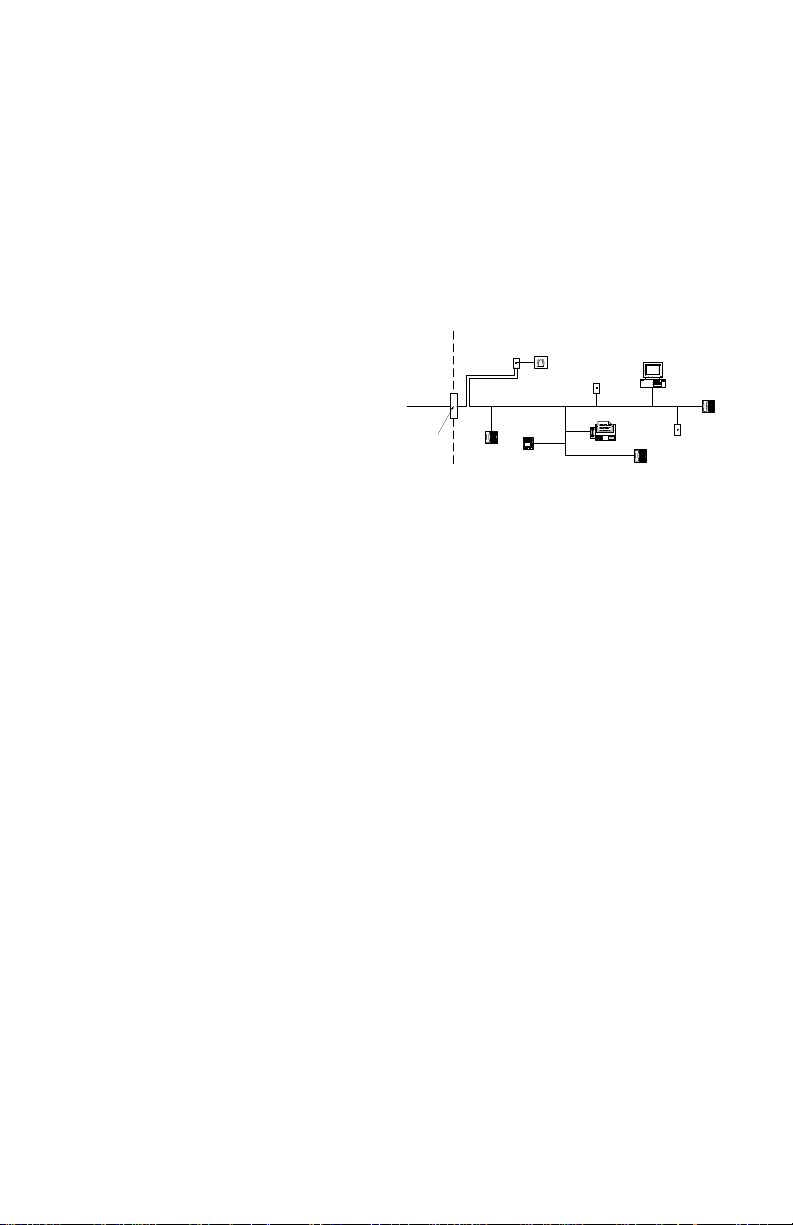
Alarm dialling equipment must be able to seize the telephone line and place
a call in an emergency situation. It must be able to do this even if other
equipment (telephone, answering system, computer modem, etc.) already
has the telephone line in use. To do so, alarm dialling equipment must be
connected to a properly installed RJ-31X jack that is electrically in series
with and ahead of all other equipment attached to the same telephone line.
Proper installation is depicted in the figure below. If you have any questions
concerning these instructions, you should consult your telephone company
or a qualified installer about installing the RJ-31X jack and alarm dialling
equipment for you.
Customer Premises Equipment and Wiring
Network
Service
Provider's
Facilities
Telephone
Line
Network
Demarcation
Point
Industry Canada Compliance Statement
This Equipment meets the applicable Industry Canada Terminal Equipment
Technical Specifications. This is confirmed by the registration number . The
abbreviation, IC, before the registration number signifies that registration
was performed based on a Declaration of Conformity indicating that Industry
Canada technical specifications were met. It does not imply that that Industry
Canada approved the equipment. The Ringer Equivalence Number (REN)
for this terminal equipment is 0.0. The REN assigned to each terminal
equipment provides an indication of the maximum number of terminals
allowed to be connected to a telephone interface. The termination on an
interface may consist of any combination of devices subject only to the
requirement that the sum of the Ringer Equivalence Numbers of all devices
does not exceed 5.
Cet équipement est conforme aux spécifications techniques applicables aux
équipements terminaux d'Industrie Canada. Ceci est confirmé par le numéro
d'enregistrement. L'abréviation IC précédant le numéro d'enregistrement
signifie que l'enregistrement a été effectué sur la base de la Déclaration de
conformité indiquant que le produit est conforme aux spécifications
techniques d'Industrie Canada. Ceci n'implique pas que le produit ait été
approuvé par Industrie Canada.
Le nombre équivalent de sonneries (REN) de cet appareil terminal est 0.0. Le
REN attribué à chaque équipement terminal fournit une indication sur le nombre
maximum de terminaux pouvant être connectés sur une interface téléphonique.
La terminaison sur une interface peut constituer en n'importe quelle combinaison
d'appareils, à la condition seulement que la somme des Nombres équivalents de
sonneries de tous les appareils ne soit pas supérieure à 5.
This Class B digital apparatus meets all requirements of the Canadian
interference-causing equipment regulations. Cet appareil numérique de la
Classe B respecte toutes les exigences de règlement sur le matériel brouilleur
du Canada.
The term “IC:” before the radio certification number only signifies that
Industry Canada technical specifications were met.
Telephone
RJ-31X
Jack
Alarm Dialing
Equipment
Answering
System
Unused
RJ-11 Jack
Fax Machine
Telephone
Computer
Unused
RJ-11 Jack
Telephone
W ARNING: To satisfy FCC RF exposur e r equirements for mobile transmitting devices, a separation distance of
20cm or more must be maintained between the antenna of this device and persons during device operation.

INTRODUCTION
The GS3060 is a backup wireless communicator that sends alarm system information to a System
III or System II receiver through a GSM/GPRS wireless network or to a standard land-line receiver
through the GSM voice channel. For use with listed compatible control units as indicated in the
control unit manufacturer's installation instructions.
Features
• Compatible with any listed panel that supports 4 or 10-digit Contact ID
• Simulates land line
• Switches automatically to GSM network in the event of land line trouble (line down)
• GSM Signal Indicator
• 4 programmable outputs
• Houses 12V - 1.2 Ah battery
• Case Tamper Output
• Land-line Overvoltage Protection
• Dual-Band GSM Radio
• 4 Programmable Inputs
• GPRS/Internet communication with Sur-Gard System III / II
• PTM Feature 4 phone numbers programmable for Contact ID Dialer
• 4 numbers programmable for Contact ID Dialer through GSM voice channels
Technical Specifications
The input voltage to the GS3060
an external UL Listed power supply rated for the application (external power-limited source).
NOTE: The power supply must be Class II, Power Limited.
Ratings
Power Supply RatingsPower Supply Ratings
Power Supply Ratings
Power Supply RatingsPower Supply Ratings
Input Voltage:............................................................................................ 9 - 14V
Current: .............................. 120mA* (JP3 - OFF and internal battery required) or 500mA* (JP3 ON)
* Plus any current drawn from the GS3060 AUX+ terminal
Battery: ........................................................................ sealed, rechargeable type, rated 12V/1.2Ah
NOTE: Battery must be replaced every 3-5 years.
Recharging current: .................................................................................................................. 50mA
CurCur
rr
ent consumptionent consumption
Cur
r
ent consumption
CurCur
rr
ent consumptionent consumption
Standby current: ...................................................................................................................... 120mA
Alarm (Transmitting) current: ................................................................................................... 450mA
PGM outputs: ....................................................................................... 4, open collector, rated 50mA
Operating frequency: ................................................................................................... 850/1900MHz
Antenna Gain: ........................................................................................................................... 2.0dBi
EnvirEnvir
onmental specificationsonmental specifications
Envir
onmental specifications
EnvirEnvir
onmental specificationsonmental specifications
Operating temperature: .................................................................................. 0°C-49°C (32°F-120°F)
Humidity: ................................................................................. 93%RH Maximum (Non-Condensing)
Mechanical specificationsMechanical specifications
Mechanical specifications
Mechanical specificationsMechanical specifications
Metal enclosure, painted; dimensions: ...................... 138mm x 224mm x 55mm / 5.4” x 8.8” x 2.2”
Weight (without battery): ................................................................................................ 900g / 3.2oz
Internal Event Buffer (communications): .................................................. 256 Events (not viewable)
Maximum loop resistance of line between the device connected in series on T1/R1: ........ 1KOhm
can be drawn from the UL/ULC Listed Control Panel or provided by
DC (13.8VDC typical)
1
 Loading...