

Tyco Safety Canada 079047 User Manual

WARNING: This manual contains information on limitations regarding
product use and function and information on the limitations as to liability of
the manufacturer. The entire manual should be carefully read.
User Manual
Self Contained Wireless
S E C U R I T Y S Y S T E M
FCC COMPLIANCE STATEMENT
Telephone
Computer
Telephone
Telephone
Fax Machine
Alarm Dialing
Equipment
RJ-31X
Jack
Unused
RJ-11 Jack
Telephone
Line
Network
Service
Provider's
Facilities
Customer Premises Equipment and Wiring
Unused
RJ-11 Jack
Network
Demarcation
Point
Answering
System
This DSC SCW9047-433
Security System may be
connected to the Telecom
Network
PTC XXX / XX / XXX
X.X = NR
CAUTION: Changes or modifications not expressly approved by Digital Security Controls could void your authority to use this equipment.
This equipment has been tested and found to comply with the limits for a
Class B digital device, pursuant to Part 15 of the FCC Rules. These limits
are designed to provide reasonable protection against harmful interference in a residential installation. This equipment generates, uses and can
radiate radio frequency energy and, if not installed and used in accordance with the instructions, may cause harmful interference to radio communications. However, there is no guarantee that interference will not
occur in a particular installation. If this equipment does cause harmful interference to radio or television reception, which can be deter-mined by
turning the equipment off and on, the user is encouraged to try to correct
the interference by one or more of the following measures:
• Re-orient the receiving antenna.
• Increase the separation between the equipment and receiver.
• Connect the equipment into an outlet on a circuit different from that
to which the receiver is connected.
• Consult the dealer or an experienced radio/television technician for
help.
The user may find the following booklet prepared by the FCC useful:
"How to Identify and Resolve Radio/Television Interference Problems".
This booklet is available from the U.S. Government Printing Office,
Washington D.C. 20402, Stock # 004-000-00345-4.
IMPORTANT INFORMATION
This equipment complies with Part 68 of the FCC Rules and, if the
product was approved July 23, 2001 or later, the requirements adopted
by the ACTA. On the side of this equipment is a label that contains,
among other information, a product identifier. If requested, this number
must be provided to the Telephone Company.
Product Identifier: US:F53AL01B9047
USOC Jack: RJ-31X
Telephone Connection Requirements
A plug and jack used to connect this equipment to the premises wiring
and telephone network must comply with the applicable FCC Part 68
rules and requirements adopted by the ACTA. A compliant telephone
cord and modular plug is provided with this product. It is designed to
be connected to a compatible modular jack that is also compliant. See
installation instructions for details.
Ringer Equivalence Number (REN)
The REN is used to determine the number of devices that may be connected to a telephone line. Excessive RENs on a telephone line may result in the devices not ringing in response to an incoming call. In most
but not all areas, the sum of RENs should not exceed five (5.0). To be
certain of the number of devices that may be connected to a line, as determined by the total RENs, contact the local Telephone Company. For
products approved after July 23, 2001, the REN for this product is part
of the product identifier that has the format US: AAAEQ##TXXXX.
The digits represented by ## are the REN without a decimal point (e.g.,
03 is a REN of 0.3). For earlier products, the REN is separately shown
on the label.
REN = 0.1B
Incidence of Harm
If this equipment ( SCW9047/SCW9045) causes harm to the telephone
network, the telephone company will notify you in advance that temporary discontinuance of service may be required. But if advance notice is
not practical, the Telephone Company will notify the customer as soon as
possible. Also, you will be advised of your right to file a complaint with
the FCC if you believe it is necessary.
Changes in Telephone Company Equipment or Facilities
The Telephone Company may make changes in its facilities, equipment,
operations or procedures that could affect the operation of the equipment.
If this happens the Telephone Company will provide advance notice in
order for you to make necessary modifications to maintain uninterrupted
service.
Equipment Maintenance Facility
If trouble is experienced with this equipment ( SCW9047/SCW9045) for
repair or warranty information, contact the facility indicated below. If the
equipment is causing harm to the telephone network, the Telephone
Company may request that you disconnect the equipment until the problem is solved. This equipment is of a type that is not intended to be repaired by the end user.
DSC c/o APL Logistics 757 Douglas Hill Rd, Lithia Springs, GA
30122
Additional Information
Connection to party line service is subject to state tariffs. Contact the state
public utility commission, public service commission or corporation
commission for information.
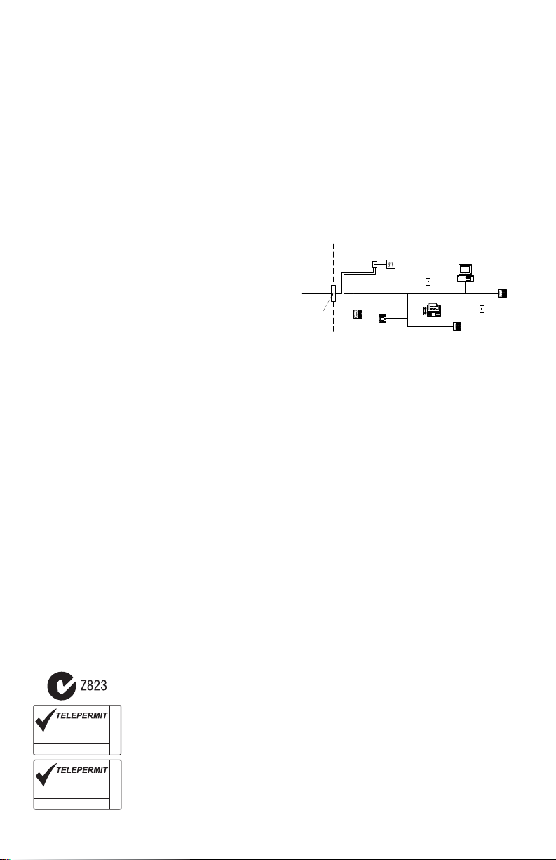
Alarm dialing equipment must be able to seize the telephone line and
place a call in an emergency situation. It must be able to do this even if
other equipment (telephone, answering system, computer modem, etc.)
already has the telephone line in use. To do so, alarm dialing equipment
must be connected to a properly installed RJ-31X jack that is electrically
in series with and ahead of all other equipment attached to the same telephone line. Proper installation is depicted in the figure below. If you have
any questions concerning these instructions, you should consult your telephone company or a qualified installer about installing the RJ-31X jack
and alarm dialing equipment for you.
INDUSTRY CANADA STATEMENT
NOTICE: This product meets the applicable Industry Canada technical
specifications.
Le présent materiel est conforme aux specifications techniques applicables d’Industrie Canada.
The Ringer Equivalence Number (REN) for this terminal equipment is 0.1 .
L'indice d'équivalence de la sonnerie (IES) du présent matériel est de 0.1.
The Ringer Equivalence Number is an indication of the maximum
number of devices allowed to be connected to a telephone interface.
The termination on an interface may consist of any combination of devices subject only to the requirement that the sum of the RENs of all the
devices does not exceed five.
L’indice d’équivalence de la sonnerie
(IES) sert à indiquer le nombre maximal de terminaux qui peuvent être
raccordés à une interface téléphonique. La terminaison d’une interface
peut consister en une combinaison quelconque de dispositifs, à la seule
condition que la somme d’indices d’équivalence de la sonnerie de tous
les dispositifs n’excède pas 5.
The term “IC:” before the radio certification number only signifies that
Industry Canada technical specifications were met.
Certification Number IC: 160A-9047
This Class B digital apparatus complies with Canadian ICES-003.
Cet appareil numérique de la classe B est conforme à la norme NMB-
003 du Canada.
New Zealand - The following is a list of warnings applicable when this equipment is connected to the New Zealand Telecom Network.
General Warning
The grant of a Telepermit for any item of terminal equipment indicates only that Telecom has accepted that the
item complies with minimum conditions for connection to its network. It indicates no endorsement of the product
by Telecom, nor does it provide any sort of warranty. Above all, it provides no assurance that any item will work
correctly in all respects with another item of Telepermitted equipment of a different make or model, nor does it
imply that any product is compatible with all of Telecom's network services.
Reverse Numbering (decadic signalling)
Decadic signalling should not be used as it is being progressively phased out of the network. DTMF dialling is
100% available and it should always be used.
Line Grabbing Equipment
This equipment is set up to carry out test calls at pre-determined times. Such test calls will interrupt any other
calls that may be set up on the line at the same time. The timing set for such test calls should be discussed with the
This DSC SCW9045-433
Security System may be
connected to the Telecom
Network
PTC XXX / XX / XXX
installer.
The timing set for test calls from this equipment may be subject to 'drift'. If this proves to be inconvenient and
X.X = NR
your calls are interrupted, then the problem of timing should be discussed with the equipment installer. The matter should NOT be reported as a fault to Telecom Faults Service.
D.C. Line Feed to Other Devices
During dialling, this device unit does not provide DC voltage to the series port connection and this may cause loss
of memory functions for the terminal devices (local telephone) connected to T-1, R-1.
General Operation (ringer sensitivity and loading)
This device only responds to Distinctive Alert cadences DA1 and DA2.

About Your Security System . . . . . . . . . . . . . . . . . . . . . . . . . . . . . . . . . . . . . . . . . . 1
Table of Contents
Fire Detection . . . . . . . . . . . . . . . . . . . . . . . . . . . . . . . . . . . . . . . . . . . . . . . . . . . . 1
Testing . . . . . . . . . . . . . . . . . . . . . . . . . . . . . . . . . . . . . . . . . . . . . . . . . . . . . . . . . 1
Monitoring . . . . . . . . . . . . . . . . . . . . . . . . . . . . . . . . . . . . . . . . . . . . . . . . . . . . . . . 1
Maintenance . . . . . . . . . . . . . . . . . . . . . . . . . . . . . . . . . . . . . . . . . . . . . . . . . . . . . 1
General System Operation . . . . . . . . . . . . . . . . . . . . . . . . . . . . . . . . . . . . . . . . . . 1
Controls & Indicators. . . . . . . . . . . . . . . . . . . . . . . . . . . . . . . . . . . . . . . . . . . . . . . . . 2
Language Selection . . . . . . . . . . . . . . . . . . . . . . . . . . . . . . . . . . . . . . . . . . . . . . . . . 2
Arming & Disarming the System . . . . . . . . . . . . . . . . . . . . . . . . . . . . . . . . . . . . . . . 2
Arming (Turning On/Setting). . . . . . . . . . . . . . . . . . . . . . . . . . . . . . . . . . . . . . . . . 2
Away Arming (Turned On/Set) . . . . . . . . . . . . . . . . . . . . . . . . . . . . . . . . . . . . . . . 2
Quick Exit . . . . . . . . . . . . . . . . . . . . . . . . . . . . . . . . . . . . . . . . . . . . . . . . . . . . . . . 2
Bell/Siren Sounds After Away Arming . . . . . . . . . . . . . . . . . . . . . . . . . . . . . . . . . 3
Disarming (Turning Off /Unsetting) . . . . . . . . . . . . . . . . . . . . . . . . . . . . . . . . . . . . 3
Stay Arming (Partially Turning On / Part Setting) . . . . . . . . . . . . . . . . . . . . . . . . . 3
Night Arming . . . . . . . . . . . . . . . . . . . . . . . . . . . . . . . . . . . . . . . . . . . . . . . . . . . . . 3
Silent Exit Delay . . . . . . . . . . . . . . . . . . . . . . . . . . . . . . . . . . . . . . . . . . . . . . . . . . 3
Remote Arming and Disarming . . . . . . . . . . . . . . . . . . . . . . . . . . . . . . . . . . . . . . 4
Emergency Keys . . . . . . . . . . . . . . . . . . . . . . . . . . . . . . . . . . . . . . . . . . . . . . . . . . . . 4
When Alarm Sounds. . . . . . . . . . . . . . . . . . . . . . . . . . . . . . . . . . . . . . . . . . . . . . . 4
Intrusion (Burglar) Alarm Continuous Siren . . . . . . . . . . . . . . . . . . . . . . . . . . . . . 4
Fire Alarm Pulsed Siren . . . . . . . . . . . . . . . . . . . . . . . . . . . . . . . . . . . . . . . . . . . . . . 4
Time & Date Programming . . . . . . . . . . . . . . . . . . . . . . . . . . . . . . . . . . . . . . . . . . . . 4
Bypassing Zones . . . . . . . . . . . . . . . . . . . . . . . . . . . . . . . . . . . . . . . . . . . . . . . . . . . 4
Trouble Conditions . . . . . . . . . . . . . . . . . . . . . . . . . . . . . . . . . . . . . . . . . . . . . . . . . . 6
Alarm Memory . . . . . . . . . . . . . . . . . . . . . . . . . . . . . . . . . . . . . . . . . . . . . . . . . . . . . . 6
Door Chime (Entry/Exit Beeps) . . . . . . . . . . . . . . . . . . . . . . . . . . . . . . . . . . . . . . . . 6
Access Code Programming . . . . . . . . . . . . . . . . . . . . . . . . . . . . . . . . . . . . . . . . . . . 6
Access Codes . . . . . . . . . . . . . . . . . . . . . . . . . . . . . . . . . . . . . . . . . . . . . . . . . . . . . . 7
User Code Attributes . . . . . . . . . . . . . . . . . . . . . . . . . . . . . . . . . . . . . . . . . . . . . . . . 7
Bell Squawk Attribute . . . . . . . . . . . . . . . . . . . . . . . . . . . . . . . . . . . . . . . . . . . . . . . . 7
Erasing an Access Code . . . . . . . . . . . . . . . . . . . . . . . . . . . . . . . . . . . . . . . . . . . . . 7
User Function Commands . . . . . . . . . . . . . . . . . . . . . . . . . . . . . . . . . . . . . . . . . . . . 8
Changing Brightness/Contrast . . . . . . . . . . . . . . . . . . . . . . . . . . . . . . . . . . . . . . . . 8
Changing the Buzzer Level . . . . . . . . . . . . . . . . . . . . . . . . . . . . . . . . . . . . . . . . . . . 8
i

Viewing the Event Buffer . . . . . . . . . . . . . . . . . . . . . . . . . . . . . . . . . . . . . . . . . . . . . 8
This publications covers the following models:
•SCW9047-433
•SCW9045-433
•SCW9047-868†
•SCW9045-868†
† These models are not UL/ULC Listed (intended for European market)
Reference Sheets . . . . . . . . . . . . . . . . . . . . . . . . . . . . . . . . . . . . . . . . . . . . . . . . . . . . 9
System Information. . . . . . . . . . . . . . . . . . . . . . . . . . . . . . . . . . . . . . . . . . . . . . . . 9
Access Codes. . . . . . . . . . . . . . . . . . . . . . . . . . . . . . . . . . . . . . . . . . . . . . . . . . . . 9
Sensor / Zone Information . . . . . . . . . . . . . . . . . . . . . . . . . . . . . . . . . . . . . . . . . 10
Testing Your System . . . . . . . . . . . . . . . . . . . . . . . . . . . . . . . . . . . . . . . . . . . . . . . 11
Testing Your System Sounder . . . . . . . . . . . . . . . . . . . . . . . . . . . . . . . . . . . . . . 11
Testing Your Entire System . . . . . . . . . . . . . . . . . . . . . . . . . . . . . . . . . . . . . . . . 11
Walk Test Mode . . . . . . . . . . . . . . . . . . . . . . . . . . . . . . . . . . . . . . . . . . . . . . . . . 11
Allowing Computer Access To Your System . . . . . . . . . . . . . . . . . . . . . . . . . . . 11
Guidelines for Locating Smoke Detectors . . . . . . . . . . . . . . . . . . . . . . . . . . . . . . 12
Household Fire Safety Audit . . . . . . . . . . . . . . . . . . . . . . . . . . . . . . . . . . . . . . . . . 13
Fire Escape Planning . . . . . . . . . . . . . . . . . . . . . . . . . . . . . . . . . . . . . . . . . . . . . . . 13
ii

About Your Security System
Your Security System has been designed to provide you with the greatest possible flexibility and convenience. Read this manual carefully and have your installer instruct you on your system's operation
and on which features have been implemented in your system. All users of this system should be
equally instructed in its use. Fill out the “System Information” page with all of your zone information
and access codes and store this manual in a safe place for future reference.
NOTE: The Self Contained Wireless Security System includes specific false alarm reduction features and is classified in accordance with ANSI/ SIA CP-01-2000 Control Panel Standard - Features for False Alarm Reduction. Please consult your installer for further information regarding
the false alarm reduction features built into your system as all are not covered in this manual.
Fire Detection
This equipment is capable of monitoring fire detection devices such as smoke detectors and providing a warning if a fire condition is detected. Good fire detection depends on having adequate number of detectors placed in appropriate locations. This equipment should be installed in accordance
with NFPA 72 (N.F.P.A., Batterymarch Park, Quincey MA 02269). Carefully review the Family Escape
Planning guidelines in this manual.
NOTE: Your installer must enable the fire detection portion of this equipment before it becomes
functional.
Testing
To insure that your system continues to function as intended, you must test your system weekly.
Please refer to the “Testing your System” section in this manual. If your system does not function
properly, call your installing company for service.
Monitoring
This system is capable of transmitting alarms, troubles & emergency information to a central station. If you
initiate an alarm by mistake, immediately call the central station to prevent an unnecessary response.
NOTE: The monitoring function must be enabled by the installer before it becomes functional.
NOTE: This system has a communicator delay of 30 seconds. It can be removed, or it can be in-
creased up to 45 seconds by the installer.
Maintenance
With normal use, the system requires minimum maintenance. Note the following points:
• Do not wash the security equipment with a wet cloth. Light dusting with a slightly moistened cloth
should remove normal accumulations of dust.
• Use the system test described in “Testing Your System” to check the battery condition. We recommend, however, that the standby batteries be replaced every 3-5 years.
• For other system devices such as smoke detectors, passive infrared, ultrasonic or microwave motion
detectors or glassbreak detectors, consult the manufacturer’s literature for testing and maintenance
instructions.
General System Operation
Your security system comprises an integrated alarm control/keypad and various sensors and detectors. The system is mounted by the main exit/entry location. The system is self-contained; electronics,
fuses and standby battery are housed within the keypad unit.
NOTE: Only the installer or service professional should have access to the system.
The security system has several zones of area protection and each of these zones will be connected
to one or more sensors (motion detectors, glassbreak detectors, door contacts, etc.). A sensor in
alarm is indicated by messages on the LCD keypad.
Additional features include: Automatic Inhibit (Swinger Shutdown) for Alarm; Tamper and Trouble
signals after 3 occurrences in a given set period; and a Programmable Keypad Lockout option.
1
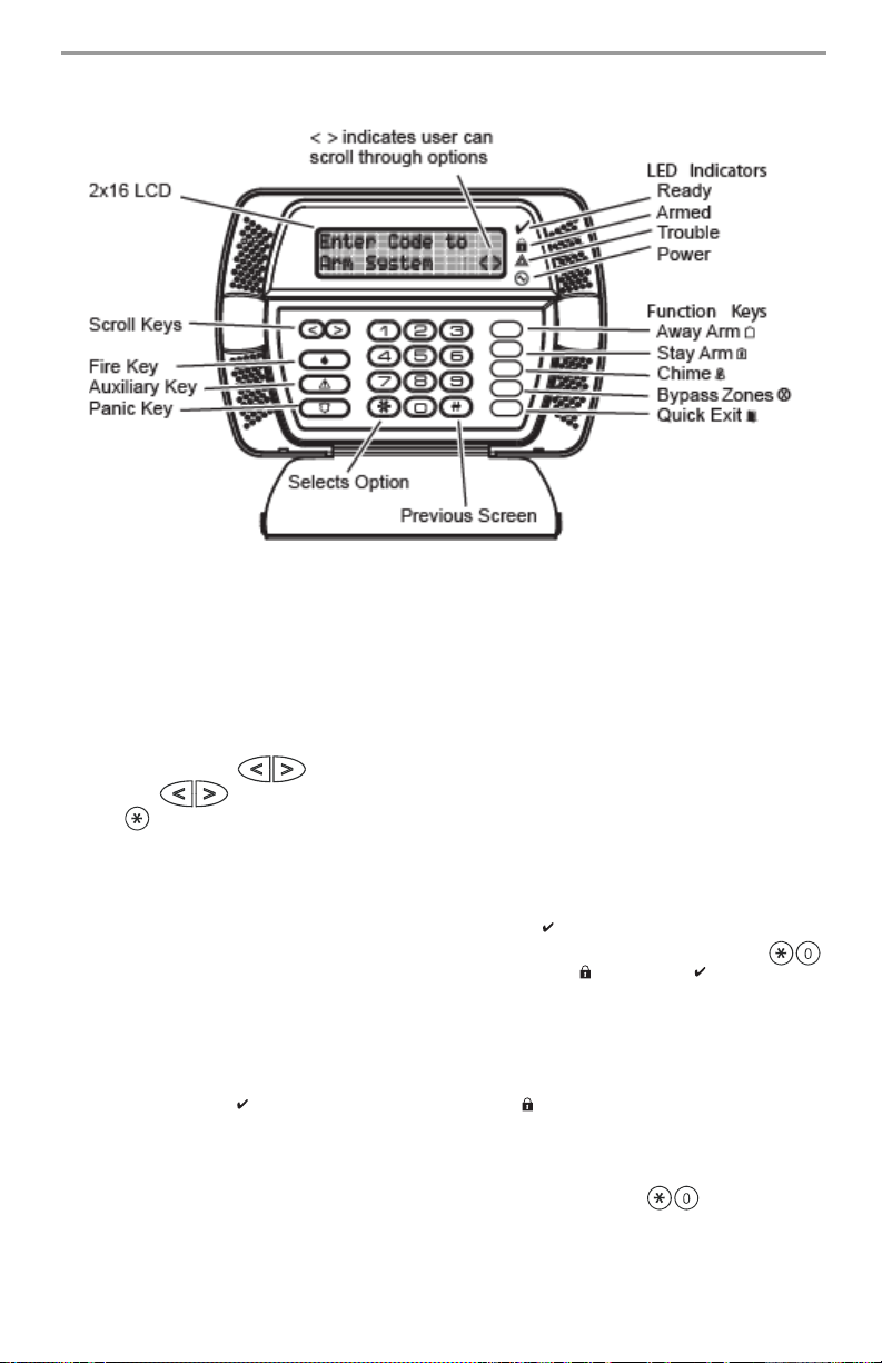
Controls & Indicators
IMPORTANT NOTICE
A security system cannot prevent emergencies. It is only intended to alert you and – if included – your
central station of an emergency situation. Security systems are generally very reliable but they may
not work under all conditions and they are not a substitute for prudent security practices or life and
property insurance. Your security system should be installed and serviced by qualified security professionals who should instruct you on the level of protection that has been provided and on system
operations.
Language Selection
Your system can display messages in different languages.
1. Press and hold both keys simultaneously.
2. Using the keys, scroll through the available languages.
3. Press to select your desired language.
Arming & Disarming the System
Arming (Turning On/Setting)
Close all sensors (i.e. stop motion and close doors). The Ready ( ) indicator should be on.
To arm, press and hold the Away Key for 2 seconds and/or enter your Access Code, or press
to Quick Arm. During the setting state (exit delay active) the Armed ( ) and Ready ( ) indicators will
turn on, and the keypad will sound one beep per second. You now have ____ seconds to leave the
premises (please check with your installer to have this time programmed). To cancel the arming
sequence, enter your access code.
Away Arming (Turned On/Set)
When the exit delay is completed, the alarm system is armed/set and this is indicated on the keypad
as follows: the Ready ( ) indicator will turn off, the Armed ( ) indicator will remain on and the keypad will stop sounding.
Quick Exit
If the system is armed and you need to exit, use the Quick Exit function to avoid disarming and
rearming the system. Press and hold the Quick Exit key for 2 seconds or press . You now have
2 minutes to leave the premises through your exit door. When the door is closed again, the remaining
exit time is cancelled.
2
 Loading...