

Tyco Safety Canada 06RFK55XX4 User Manual
Installation Instructions, Instructions d’Installation, Installatiehandleiding, Asennusohjeet
PK55XX/RFK55XX-433
English, Français, Nederlands, Suomi
123
456
78
9
0
#
*
PK5500
RFK5500
WARN ING: Pl ease refer to the System Installation Manual for information on li mitat i ons regarding product use and function a nd i nfor ma tion on t he l imit atio ns as t o li abil ity of t he manuf acturer.
NOTE: These instructions shall be used in conjunction with the system Installation Manual of t he Con trol Panel with which this equipment is intended to be used.
ATTENTION: Ce manuel contient des informations sur les restrictions concernant le fonctionnement et l’utilisation du produit et des informations sur les restrictions en ce qui concerne la responsabilité du fabri-
cant. La totalité du manuel doit être lu attentivement.
NOTE: Ce manuel doit être utilisé en conjonction avec le Manuel d'installation du Panneau de contrôle.
WAARSCHUWING: Raadpleeg de installatiehandleiding van het systeem voor informatie over beperkingen m.b.t. productgebruik en functie en informatie ov er de beperkingen m.b.t. aansprakelijkheid van de fabrikant.
OPMERKING: Deze instructies dienen te worden gebruikt in combinatie met de installatiehandleiding van het systeem van de centrale waarmee deze app ara tuur gebruikt wordt.
ADVARSEL: Vennligst se manualen for installasjon av systemet for i nform as jon om beg rensningene angående bruk og funksjon av produktet og inform as jon om begrensningene hva angår produsentens ansvar.
LEGG MERKE TIL: Disse instruksene skal brukes sammen med manualen til kontrollpanelet for installasjon av systemet som dette utstyret er ment å brukes med.
123
456
78
9
0
#
*
PK5501
RFK5501
123
456
78
9
0
#
*
PK5508
RFK5508
123
456
78
9
0
#
*
PK5516
RFK5516

English
Disasembling
(Free-standing)
1. Insert the screwdriver into
slot at an angle and push
3. Repeat steps
1. and 2. for
left side
2. Rotate 90°
Installation Instructions
The PK55XX\RFK55XX keypads can be used on security systems with
up to 64 zones. These keypads are compatible with the following DSC
security systems:
•PC580 •PC585 •PC1555MX •PC1565
•PC1616 •PC1832 •PC1864 •PC5005
•PC5008 •PC5010 •PC5015 •PC5016
•PC5020
The RFK55XX keypads combine a wireless receiver with the respective
PK55XX keypad.
Specifications
• Temperature range: -10°C to +55°C (14°F to 131°F), Tempera-
ture range for UL/ULC: 0°C to +49°C (32°F to 120°F)
• Humidity (MAX): 93%R.H.
• Plastic enclosure protection degree: IP30, IK04
• Voltage rating: 12V
• Connects to control panel via 4-wire Keybus
• 1 keypad zone input/PGM output*
• PK55XX Current draw: 50mA (standby)/125mA (maximum)
• RFK55XX Current draw: 75mA (standby)/135mA (maximum)
• Wall mount tamper
• 5 programmable function keys
• Ready (Green LED), Armed (Red LED), Trouble (Yellow LED), AC
(Green LED)
• Low temperature sensor
• Frequency: 433.92MHz
• Up to 32 wireless zones (RFK55XX Only)
NOTE: * Zone not to be programmed as Fire type or 24h type.
Unpacking
The Power keypad package includes the following parts:
•One Power keypad •Keypad inner door labels
•Four mounting screws •1 tamper switch
•2 end-of-line resistors •Installation Instructions
Mounting
You should mount the keypad where it is accessible to designated
points of entry and exit. Once you have selected a dry and secure location, perform the following steps to mount the keypad.
Disassemble Keypad
1. Removing the keypad from the backplate for the first time.
(a) Position the keypad as indicated, insert screwdriver and rotate.
DC nominal
(RFK55XX-433 Only)
2. Removing the keypad from backplate once mounted.
(a) Open door, holding it 90° to the keypad, as shown below.
(b) Insert screwdriver into slot located under the door hinge and
rotate the screwdriver.
Disasembling
(Wall-Mounted)
3. Repeat steps 1.
and 2. for right side
1. Insert the screwdriver into
slot at an angle and push
Mount and Wire Keypad
Knock Out
Knock Out
Wiring Slot
Hooks
2. Rotate 90°
Knock Out
1.
3.
1. Secure Keypad to wall using mounting holes. Use all 4 screws provided unless mounting on a single gang box.
2. Place keypad into hooks on the backplate and swing down to
engage.
3. Run wire through wiring slot or knockouts. Connect Keybus and
PGM/Zone wiring to keypad. Place tamper switch into tamper hole
on backplate.
4. Remove keypad from hooks. Place keypad into backplate, ensure
the wire is pushed back into the wall as much as possible. Route the
wire inside the keypad ensuring high components are avoided. Snap
the front assembly closed, ensuring that there is no pressure to the
keypad from the wire below.
NOTE: If any tension found between the front keypad assembly and wiring,
please open the keypad reroute the wire and close again. Repeat these
steps until the keypad is closed properly.
Wiring
1. Before wiring the unit, ensure that all power (AC transformer and
battery) is disconnected from the control panel.
2. Connect the four Keybus wires from the
control panel (red, black, yellow and
green) to the keypad terminals. Refer to
diagram:
3. If programmed as an input, you can
connect a device - such as a door contact
Tamper
- to the ‘P/Z’ terminal of the keypad.
This eliminates the need to run wires back to the control panel for
the device. To connect the zone, run one wire from the device to the
‘P/Z’ terminal and the other wire from the device to the B (black)
terminal. For powered devices, run the red wire to the R (positive)
Hooks
Tamper
2.
4.
Swing
to engage
Press to snap
PK55XX\RFK55XX
RED
BLK
YEL
GRN
To zone or
P/Z
PGM output
R
B
Y
G
terminal and the black wire to the B (negative) terminal. When
41
Toggle Option
1 _ _ 4 _ _ _ _
using end of line supervision, connect the zone according to one of
the configurations outlined in your system’s Installation Manual.
4. If the ‘P/Z’ terminal is programmed as an output, the output follows
the PGM programmed in Section [080]. A small relay, buzzer or
other DC operated device may be connected between the positive
supply voltage and the ‘P/Z’ terminal (maximum load is 50mA).
Applying Power
Once all wiring is complete, and the equipment is secured to the building structure with at least two screws apply power to the control panel:
1. Connect the battery leads to the battery.
2. Connect the AC transformer.
For more information on control panel power specifications, see the
control panel Installation Manual.
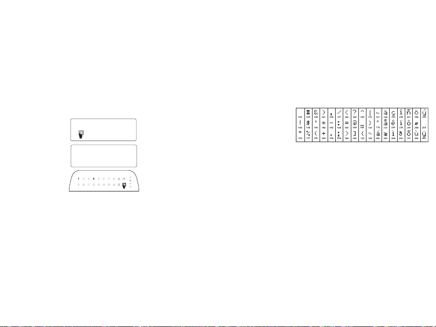
Programming the Keypad
There are several programming options available for the
keypad. These are described
below. Programming the keypad is similar to programming
the rest of the system. When
you are in the keypad programming sections, the keypad will display which options
are turned on along the top of
the display. To turn an option
on or off, press the number corresponding to the opt ion on the number
pad. The numbers of the options that are currently turned ON will be
displayed. For example, if options 1 and 4 are on, the display will
look like this on the different keypad displays:
For information on programming the rest of your security system,
please refer to your system’s Installation Manual.
Broadcasting LCD Labels
All LCD programming is done per keypad. If more than one LCD keypad is present on the system, labels programmed at one keypad can
be broadcast to all other LCD keypads. Perform the following procedure
in order to broadcast labels:
Step 1 - Program one LCD keypad completely.
Step 2 - Make sure all LCD keypads are connected to the Keybus.
Step 3 - Enter keypad programming by pressing [,][8][Installer
Code][,], then enter section [998] at the keypad that was programmed. The keypad will now broadcast all the information programmed to all the other LC D keypads on the system.
Step 4 - When the keypad is finished press the [#] key to exit.
NOTE: Label broadcast from this keypad is only compatible with other
PK5500 and RFK5500 Keypads.
Language Programming
(PK5500\RFK5500 Only)
Hold (<>) keys for 2 seconds to enter language programming,
scroll to the desired language and Press [
NOTE: If section [077] option 4 is OFF, language programming
can only be performed while in installers programming.
Enrolling the Keypad
The keypad will need to be assigned to a partition and slot if supervision or keypad zones are being used. Keypad assignments and keypad option programming must be done at each keypad individually.
The 1st digit of keypad assignment is used to determine partition
assignment (1 to 8). If partitioning is not used, enter [1]. For Global
Keypads, enter [0].
NOTE: LED and ICON keypads cannot be programmed as Global Keypads
The 2nd digit of keypad assignment is used to determine slot assignment for keypad supervision. Each keypad will be assigned a different
slot number from 1 to 8. PK5500 and RFK5500 LCD keypads come
defaulted in slot 8. If LCD keypads are used one LCD keypad must
remain in slot 8.
NOTE: The RFK55XX enrolls as two modules:
Light 1 = keypad section of the RFK55XX
Light 17 = receiver section of the RFK55XX
NOTE: Deleting all wireless devices from the RFK55XX or defaulting the
RFK55XX will cause a supervisory fault.
Enter the following at each keypad installed on the system:
1. Enter Installer Programming by pressing [,][8][Installer ’s Code]
2. Press [000] for Keypad Programming
3. Press [0] for Partition and Slot Assignment
4. Enter the 1st digit (0 to 8 for partition assignment)
5. Enter the 2nd digit (1 to 8 for slot assignment supervision)
6. Press the [#] key twice to ex it programming.
7. After assigning all keypads, perform a supervisory reset by entering
[,][8][Installer’s Code][902] and wait for 60 seconds.
8. Press the [#] key to exit programming after 60 seconds.
Programming Labels
(PK5500\RFK5500 Only)
1. Enter keypad programming by pressing [,][8][Installer Code][,].
Enter the 3-digit section number for the label to be programmed.
2. Use the arrow keys (<>) to move the underline bar underneath
the letter to be changed.
,] to select.
3. Press the number keys [1] to [9] corresponding to the letter you
require. The first time you press the number the first letter will
appear. Pressing the number key again will display the next le tter.
[1] - A, B, C , 1 [4] - J, K, L, 4 [7] - S, T, U, 7 [0] - Space
[2] - D, E, F, 2 [5] - M, N, O, 5 [8] - V, W, X, 8
[3] - G, H, I, 3 [6] - P, Q, R, 6 [9] - Y, Z, 9,0
4. When the required letter or number is displayed use the arrow keys
(<>) to scroll to the next letter.
5. When you are finished programming the Zone Label, press the [
key, scroll to “Save,” then press [
6. Continue from Step 2 un til all Labels are programmed.
NOTE: Label Programming can also be accessed from the [,][6] User
Functions Menu
ASCII Characters
Changing Brightness/Contrast
LCD Keypads
1. Press [,][6][Master code].
2. Use the [<][>] keys to scroll to either Brightness Control or Contrast Control.
3. Press [,] to select the setting you want to adjust.
4. a) ‘Brightness Control’: There are multiple backlighting levels. Use the [<][>]
keys to scroll to the desired level.
5. b) ‘Contrast Control’: There are 10 different display contrast levels. Use the
[<][>] keys to scroll to the desired contrast level.
6. To exit, press [#].
LED/ICON Keypads
1. Press [,][6][Master Code].
2. Use the [>] key to move through the 4 different backlighting levels.
3. The level is automatically saved when you press [#] to exit.
Changing the Buzzer Level
LCD Keypads
1. Press [,][6][Master Code].
2. Use the [<][>] keys to scroll to Buzzer Control.
3. There are 21 different levels, use the [<][>] keys to scroll to the desired level.
4. To exit, press [#].
LED/ICON Keypads
1. Press [,][6][Master Code].
2. Use the [<] key to move through the 21 different buzzer levels.
3. The level is automatically saved when you press [#] to exit.
,].
,]
 Loading...