

Tyco Safety Canada 06GS30552, 06GS30551 User Manual
GSM-GPRS INTERFACE

INTRODUCTION ....................................................................................................................3
FEATURES ............................................................................................................................ 3
Technical Specifications ....................................................................................................... 3
Description ............................................................................................................................ 4
IDENTIFICATION OF PARTS ............................................................................................... 4
INSTALLING THE DEVICE ................................................................................................... 4
CONNECTING THE DEVICE ................................................................................................ 4
STATUS LEDS ....................................................................................................................... 5
OPERATING PRINCIPLES ................................................................................................... 5
Simulated Land Line .............................................................................................................5
SMS Function ........................................................................................................................ 6
ContactID Mode .................................................................................................................... 6
Function Priority ..................................................................................................................... 6
Simulated Land Line Priority ....................................................................................... 6
SMS or Contact ID Priority ........................................................................................... 6
ContactID Event Priority .............................................................................................. 6
ACTIVATING THE OUTPUTS ................................................................................................ 7
Activating/Deactivating Automatic Outputs ......................................................................... 7
Activating/Deactivating Remote-control Outputs ................................................................ 7
Bistable Outputs (for appliance management) ........................................................ 7
Monostable Outputs (for appliance management) .................................................. 7
PROGRAMMING THE SIM CARD VIA PC ........................................................................... 8
Viewing the Device Settings ...................................................................................... 8
Downloading the Device Settings ............................................................................. 8
Preliminary operations ................................................................................................ 8
Telephone Page .................................................................................................................... 8
Telephone Numbers .................................................................................................... 8
Prefix ............................................................................................................................ 9
Digit to Remove ........................................................................................................... 9
SMS Dialler Page ................................................................................................................... 9
Main window ............................................................................................................... 9
Priority ....................................................................................................................... 10
Pay-as-you-go balance message ........................................................................... 10
Periodic message .................................................................................................... 1 0
Outputs Page ...................................................................................................................... 10
Output Settings ........................................................................................................ 10
Access Code ........................................................................................................... 10
Contact ID Page .................................................................................................................. 10
Telephone numbers to call ....................................................................................... 11
Events description ..................................................................................................... 11
Send over GPRS ........................................................................................................ 11
Periodic Reports ........................................................................................................ 11
GPRS page .......................................................................................................................... 11
Access Point Name ................................................................................................... 11
Receiver IP address and Port ................................................................................... 11
APNs User Name and Password ............................................................................... 11
Telephone numbers to decode ................................................................................ 11
SIM number ............................................................................................................... 11
DNIS ........................................................................................................................... 11
Account code ........................................................................................................... 11
Calls Page ............................................................................................................................ 11
Load button ............................................................................................................... 12
Received Calls .......................................................................................................... 12
Missed Calls ............................................................................................................... 12
Dialled Calls ............................................................................................................... 12
Status Page ......................................................................................................................... 12
Status section ............................................................................................................ 12
Inputs section ............................................................................................................ 12
Outputs section ......................................................................................................... 12
Events section ........................................................................................................... 12
Clear call queue ........................................................................................................ 12
"C-24 REMOTE" PROGRAMMING ..................................................................................... 1 3
INFORMATION FOR THE USER ......................................................................................... 13
Remote Programming of the Access Code ....................................................................... 13
GSM Network Calls .............................................................................................................. 13
Further Information .............................................................................................................. 13
APPENDIX .......................................................................................................................... 14
2
GS3055-I
INTRODUCTION
,,
,
This manual provides programming and operating instructions for the GS3055-I wireless alarm
,,
communicators. Information relating to a specific model will be denoted by the applicable model number
within the text. The term "Device" is used to describe functionality that is applicable to both models. This
manual shall be used in conjunction with the installation manual of the control panel and power supply it
is connected to.
FEATURES
Simulates land line
Switches automatically to GSM Network in the event land line trouble (line down)
Manages and signals Incoming/Outgoing calls
GSM signal indicator
4 programmable OC Outputs
Houses 12V - 1.2 Ah battery (not included)
Tamper protection
Land line overvoltage protection (optional)
Dual-Band
4 Input Lines
SMS Alerts
Contact ID Dialer throughout
Decoding Contact ID protocol from a PSTN interface for communication over the GPRS network
GPRS/Internet communication with Sur-Gard System III / II
13 SMS Messages (2 messages per Input Line and 5 Status messages)
8 phone numbers (max. 20 digits) programmable for SMS Dialler
4 phone numbers programmable for Contact ID Dialler
Up to 95 phone numbers (max. 20 digits) can be programmed to manage remote control of the OC Outputs
Remote control of the OC Outputs via SMS and/or over-the-phone after caller recognition
Pay-As-You-Go Balance message (for pre-paid SIM Cards)
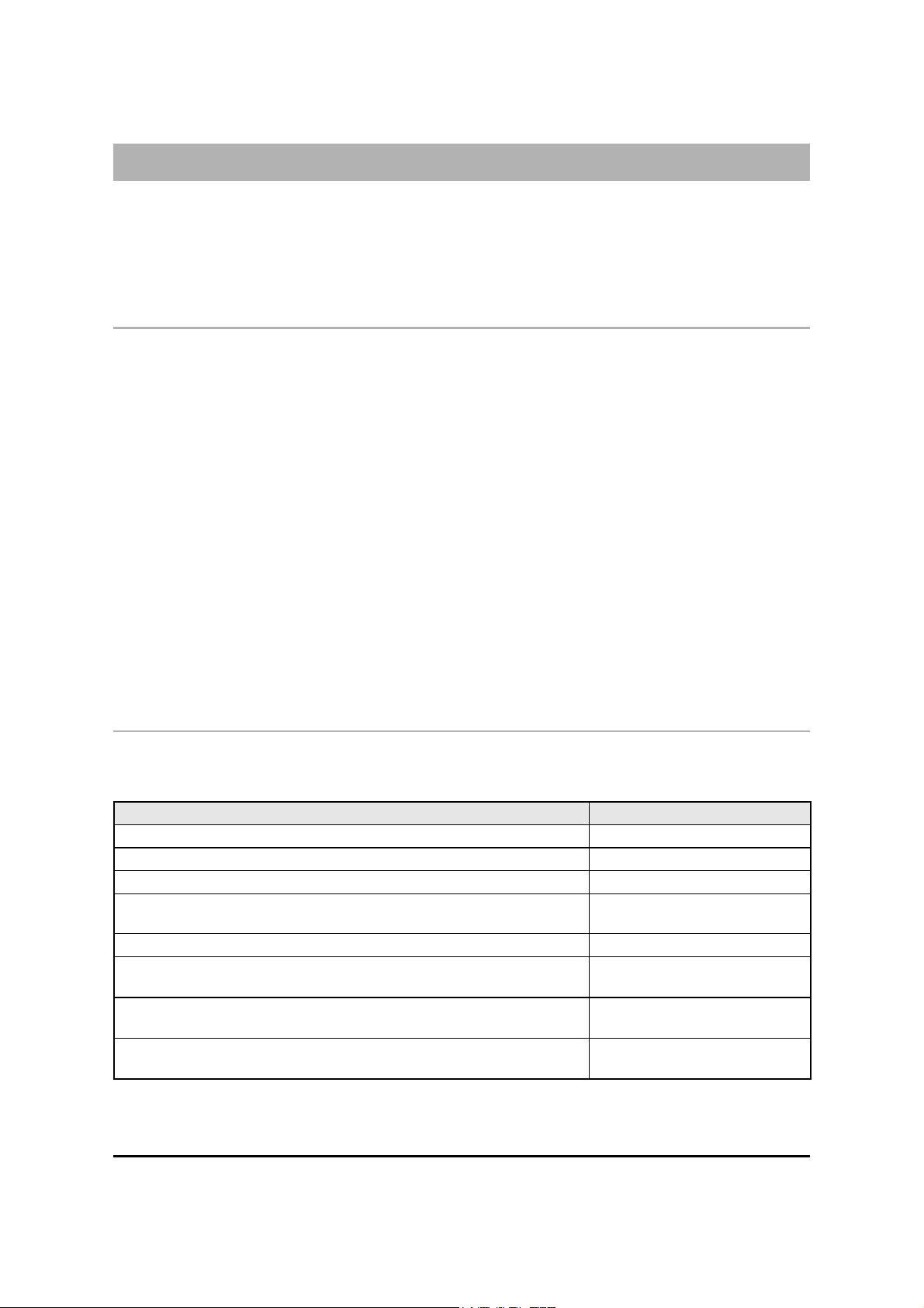
Technical Specifications
The 13.8 V_ (700 mA max.) power supply voltage to this Device can be drawn from the Control panel or provided by a
ADP1512 AC/DC adapter (accessory item) or provided by the PS4085 power supply.
Description Valu e
Power Supply voltage
Standby Current Draw
Transmitting Current Draw
Maximum loop resistance of line between the series device
and the CPE connected to the device
Maximum number of parallel CPE devices
Operating Temperature
Dimensions
Weight (wi thout battery)
13.8 V_
100 mA
700 mA
1 Kohm
2
+0° to +49° C
32 to 120 °F
138 x 224 x 55 mm
5.4 x 8.8 x 2.2 inch
900 g
3.2 oz.
3

Description
This Device provides total confidence in all security and surveillance applications. It manages SMS and Central Station
transmissions and can simulate the land line in the event of trouble (land line down) or even substitute the land line completely
in areas where the GSM service is provided and where the land line is not available.
This Device supports CONTACTID, 10 bps and 20 bps protocols and, in places with optimum GSM signal reception, SIA and
CESA protocols.
The GS3055-I has the added capability of communicating alarm signals via the GPRS data network. The capability enables
a fast reliable path to central stations equipped with a Sur-Gard System III, System II receiver, or with the PC based WinBCS
software (version 2.0 or higher).
By connecting a GS3055-I to a control panel's standard PSTN interface, telephone based Contact ID signals are decoded and
seamlessly routed through the GPRS network to any of the compatible receiver options.
The performance of this Device depends greatly on GSM Network coverage, therefore, it should not be mounted without first
performing placement tests to determine the best location (best reception). This Device has 4 Input lines which can be used to
activate SMS and/or Contact ID transmissions (Trouble alert, Periodic messages or Pay-As-You-Go Balance (for pre-paid SIM
Cards).
This Device has 4 Outputs which can be set up from remote locations or used for status signalling.
Due to the characteristics of GSM Networks, this Device can activate only as intended and cannot be used as a modem for
fax/data transmissions or for teleservice operations.
IDENTIFICATION OF PARTS
The numbers in square brackets [ ] in this manual refer to the main parts of the GS3055-I (see Fig. 1) described in this section.
INSTALLING THE DEVICE
This device shall be installed by qualified SERVICE PERSONS only. This device must be installed indoors in a nonhazardous location. This Device should be located in a dry place away from radio transmitters and similar devices.
,,
,
Test the GSM Network reception before mounting this Device in the proposed placement.
,,
1. Remove the 4 screws and the metal casing [1].
2. Using the back box, mark the 4 screw locations then drill the anchor screw holes.
Check for cable conduits and water pipes before drilling.
3. Using anchor screws (not included), mount the back box to the wall.
4. Lay the cables, then pull them through the cable entry [14].
5. Fit the antenna [2] (ensure that the bolt [3] is fastened tightly).
6. Using the connector [5], connect the GSM Module [17].
7. Following the arrow on the board, insert the SIM-CARD [6] face down in the SIM holder (see Figure 1).
The SIM-CARD PIN must be disabled.
8. Complete the connections on the terminal board [12].
9. Using the 4 scews and washers, reattach the frontplate [1] securely to the back box.
,,
,
Connect power and TNV circuit only after the cabinet has been secured to the building or structure and has
,,
been connected to the protective earth ground.
CONNECTING THE DEVICE
This section describes the various terminals. Fig. 2 shows a typical wiring diagram.
(1) Earth: This terminal must be connected to the Mains Earth, in order to comply with the Telecommunications Network
Safety Standards (Overvoltage Protection Requirements).
LE (2-3) External telephone line: These terminals can be connected to the land line.
LI (4-5) Internal telephone line: These terminals (normally connected to the land line) must be connected to the telephone
device terminals (for example, terminals L.E.).
(6-14) Negative: Power Supply.
4
GS3055-I

Ox (7-8-9-10) Programmable Open-Collector Outputs: These outputs can be activated either by programmed events
(Automatic Mode) or by SMS text messages (Remote Mode), refer to “Activating the Outputs” for details. The maximum
current draw of each OC Output must not exceed 70 mA
+OC
(2-3) Common terminal for Open-Collector Outputs: Common power-supply terminal (12 Vcc-450mA) for all OC
Outputs (O1, O2, O3, O4).
AS (12-13) Tamper: These terminals are connected in series to the Tamper microswitch [11]. They will be closed when the
Device is properly closed, and will open when the frontplate is removed.
Lx (15-16-17-18) Programmable Input line: These terminals can be set up to activate the SMS and Contact ID transmission
functions.
12V
(19-20) Device power supply: These terminals must be connected to a 13.8 V_ power supply, 700 mA minimum —
under normal circumtances drawn from a Control panel or ADP1512 Adaptor (accessory item). If the Device power
supply is drawn from a Control panel, ensure that the maximum current draw (700 mA) is protected by a
resettable fuse or similar device.
Once the connections have been completed, connect the Red and Black wires [13] to a 12V-1, 2Ah battery.
,,
,
To ensure proper operation of this Device, the connection of a backup battery is needed to provide
,,
temporary additional current during normal operation (see Fig. 2)
,,
,
This Device must be connected to a 13.8 V power supply and to a backup battery. This device must be
,,
connected to a proper Earth Ground (see Fig. 2).
,,
,
When disposing of batteries, follow the instructions and and precautions printed on the batteries, and
,,
contact your municipal offices for information on the disposal of used batteries.
STATUS LEDS
The Device Interface has 4 status LEDs.
,,
,
All 4 LEDs will blink during the Initializing and Programming phases.
,,
The following section describes the Control panel status LEDs.
GREEN — If this LED is OFF and the RED LED is ON, the GSM Network service is unavailable (NO SERVICE).
This LED will Blink when the GSM Network reception is bad, if this occurs, only SMS transmissions will be possible.
If this LED is ON (glowing), the GS3050-I and GS3055-I Interface will be able to manage all telephone communications.
GREEN — When this LED is ON (glowing), the reception is good. This LED will switch ON only when the other GREEN
LED is ON (glowing).
AMBER — This LED will switch ON (glowing) when the interface switches to the GSM Network (due to land line trouble).
This LED will Blink in the event of an incoming or outgoing call (regardless of the operating status of the land line).
RED — This LED is Normally OFF, it will blink in the event of power trouble. This LED will switch ON (glowing) in the
event of GSM Module [17] trouble, or when the GSM Network is unavailable (NO SERVICE), or when Remote
Programming option is enabled. If this LED switches ON (glowing), and the two Green LEDs indicate the availability of
the GSM Network service, ONLY Emergency calls will be possible.
OPERATING PRINCIPLES
Simulated Land Line
The Simulated land line provides traditional telephone devices with a backup line in the event of land line trouble (line down). This
operating mode will allow calls and data transmissions to be carried on the land line. If the voltage on the land line terminals (LE)
drops below 3 V for a period of between 10 to 45 seconds (depending on the device connected to the LI terminals), the Device
will switch the connected telephone device to the GSM Network for a full 15 minute interval, at the end of this interval, it will
check the land line:
— if the land line has been restored, it will switch the connected telehone device back to the land line;
— if the land line is still down, it will continue to simulate the land line until remove it is fully restored.
5
 Loading...